Filabot EX6 User manual
REV.14‐8‐2019
Filabot
Vermont, USA, Earth
1-802-505-6772
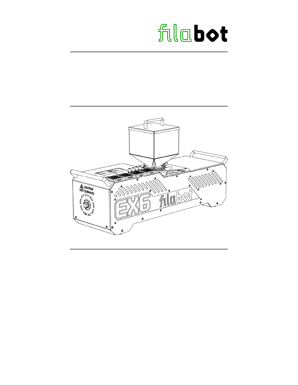
Filabot EX6 Extruder
Operation Manual
This manual applies to the Filabot EX6.
Triex LLC, Barre, VT 05641, USA

1
CAUTION! Read Carefully
HOT MATERIALS & SURFACES Use gloves and eye protection
while operating the EX6 Extruder. The barrel and nozzle are HOT
and melted plastic can stick to the skin and cause serious injury.
HIGH-PRESSURE EXPLOSION Air trapped inside the barrel
becomes highly pressurized during operation and can cause small
explosions out of the nozzle which will throw molten plastic away in
any direction.
TOXIC FUMES Some plastics like PVC can produce dangerously
toxic fumes when they are heated. Always carefully review the
MSDS of any material before using it in the EX6 to avoid dangers to
your health. Always use the EX6 in a well-ventilated area.
In Case of Emergency pull the power cord out of the machine.
Only use the EX6 to extrude thermoplastic polymers. No other use
has been tested or approved by Filabot.
Always STOP the extruder before clearing the feed port or removing
the screw. Never stick anything into the feed port while the screw is
turning as this could damage your system.
The EX6 is designed for indoor use only. Operate in a clean, dry
area.
Check the AC input voltage specified on the S/N Label near the
power inlet. Only use the specified input voltage to operate the EX6
or damage to the components could occur.
Do not use this device if any parts appear missing or damaged.
Do not modify this device without authorization from Filabot.
Contact Filabot with any questions
1-802-505-6772

2
General Specifications
Power Input: 120VAC-13A or 240VAC-6.5A 50/60Hz 1-Phase
1550W MAX - varies with settings
Check S/N Label for proper input voltage
Input Connector Type: IEC 320-C14
Weight: 23kg (50 lbs)
Dimensions: 75.44cm L x 23.11cm W x 21.34cm H(29.7in L x 9.1in
W x 9.75in H) (No Hopper)
Hopper Dimensions: 15.24cm L x 15.24cm W x 21.34cm H (6in L x 6in
W x 8.4in H)
Hopper Volume: 3195.5 cubic cm (195in³)
Total Height: 41.4cm (16.3in) H
(With Hopper)
Temperature Control: 3 PID Controlled Barrel Heat Zones
(aluminum blocks with dual 150W heaters)
1 PID Controlled Feed Throat Heat Zone
2 Manual Speed Controlled Barrel Fans
1 Manual Speed Controlled Feed Throat Fan
1 Manual Speed Controlled Motor Fan
Max Recommended Run Temp: 660°F (350°C)
Drive Control: 0-90VDC PWM Speed Controller with
5A Max Current Limiter
Drive Motor: 1/2 HP 90VDC 4.6A
100 RPM
Torque: 24.3 N*m (215 in-lb)
Gear Ratio 28:1
Grease Lubricated Spur Gearing
Screw: Part # EX6-625
16mm (5/8") Diameter
1/2” Pitch
24 L/D Ratio
17-4 PH Stainless Steel Con. H900
2:1 Compression
Nozzle: Type “X” (7/8"-14 Thread)
3
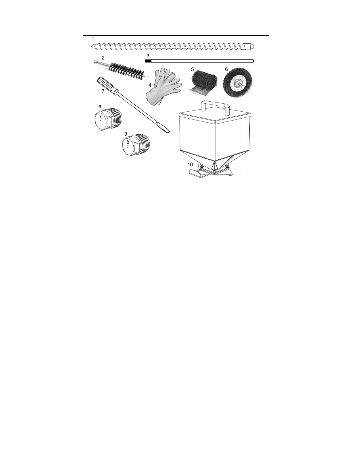
Parts Included
1. Extrusion Screw 5/8” OD 2:1 Comp
2. Brass Bristle Tube Cleaner
3. Tube Cleaner Extension Rod
4. High-Temperature Resistant Terry Cloth Gloves
5. Copper Gauze
6. Brass Bristle Wheel
7. Brass Flared Tip Pry Tool
8. 1.75mm Bore Nozzle
9. 2.85mm Bore Nozzle
10. 195in³ (3.2L) Slide Valve Hopper with Lid
11. 2x 1lb Bags of Extruder Purge Compound
Tools Required:
Non-marring bench vice (with V-block) for holding screw while cleaning
Powered Drill with a chuck that can receive a 5/16” or larger shank
3/4” Wrench (for nozzles)
Automotive grade wheel bearing grease (small amount)
Recommended:
Never-Seize/Anti-Seize thread lubricant (450ºC rated or higher)
Compressed air & air blower/duster gun
Heat gun or propane torch
Shop Vacuum Cleaner
Filabot Spooler
Filabot Airpath
Call 1-802-505-6772 or visit Filabot.com for additional/replacement parts
4
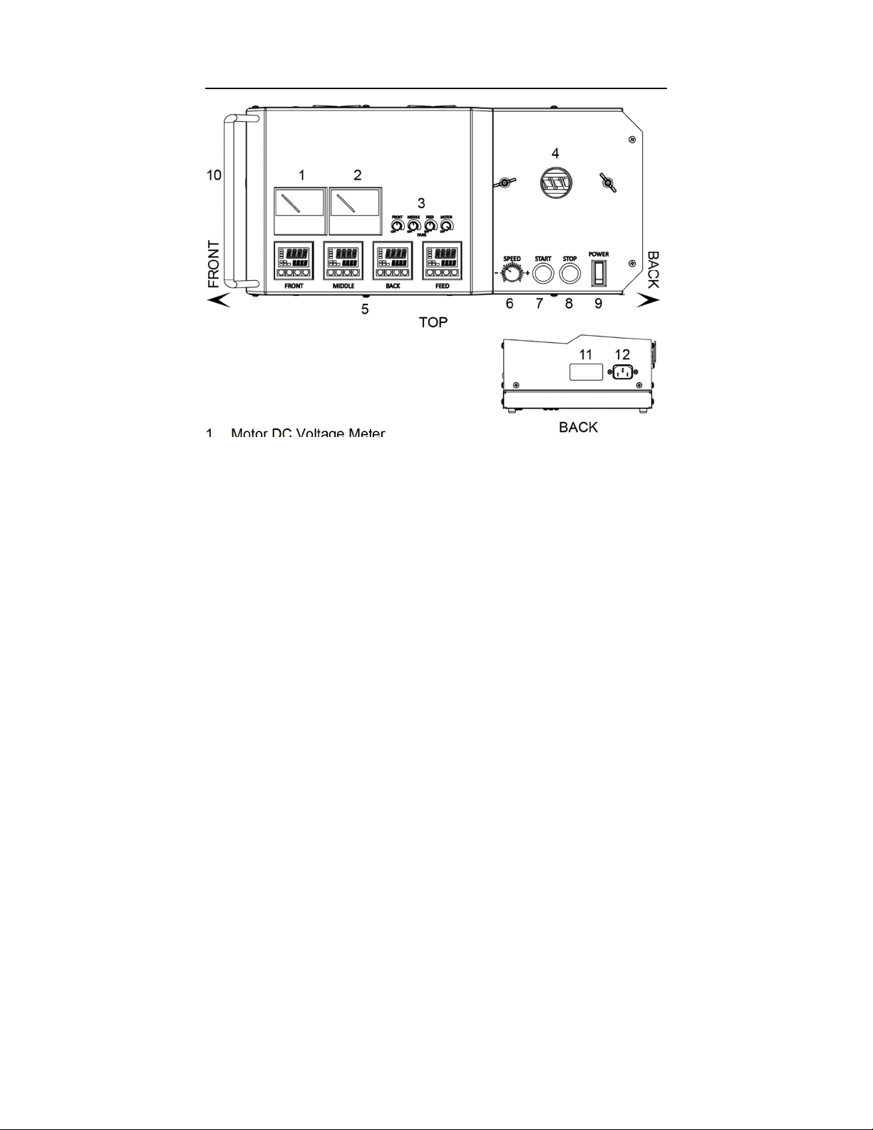
Controls & Inputs
1. Motor DC Voltage Meter
2. Motor DC Amperage Meter
3. Fan Speed Controls (recommended first use settings pictured):
FRONT - Cools barrel between FRONT and MIDDLE heat zones
MIDDLE - Cools barrel between MIDDLE and BACK heat zones
FEED - Cools feed throat
MOTOR - Cools DC motor
4. Feed port for polymer pellets
5. PID Heat Zones
FRONT - Metering section heat zone (nozzle end)
MIDDLE - Compression section heat zone
BACK - Feed/compression section heat zone (feed end)
FEED - Feed port temperature heat zone
6. Motor voltage/speed control knob (0-90VDC)
7. Motor start button
8. Motor stop button
9. Main power switch (thermal breaker)
10. Extrusion nozzle polymer output (front end of the barrel)
11. Serial Number & Voltage Input Label
12. AC Power Input Connector Type: IEC 320-C14
5
First Use & Tuning - Initial Settings
1. Use the EX6 in an open area on a flat, clean surface with plenty of
room to move around the extruder and allow for heat dissipation from
the vents.
2. Plug the machine into a power outlet with the specified input voltage.
3. Turn on the “POWER” switch. All PID Temperature controllers will
turn on, and the "STOP" button will illuminate.
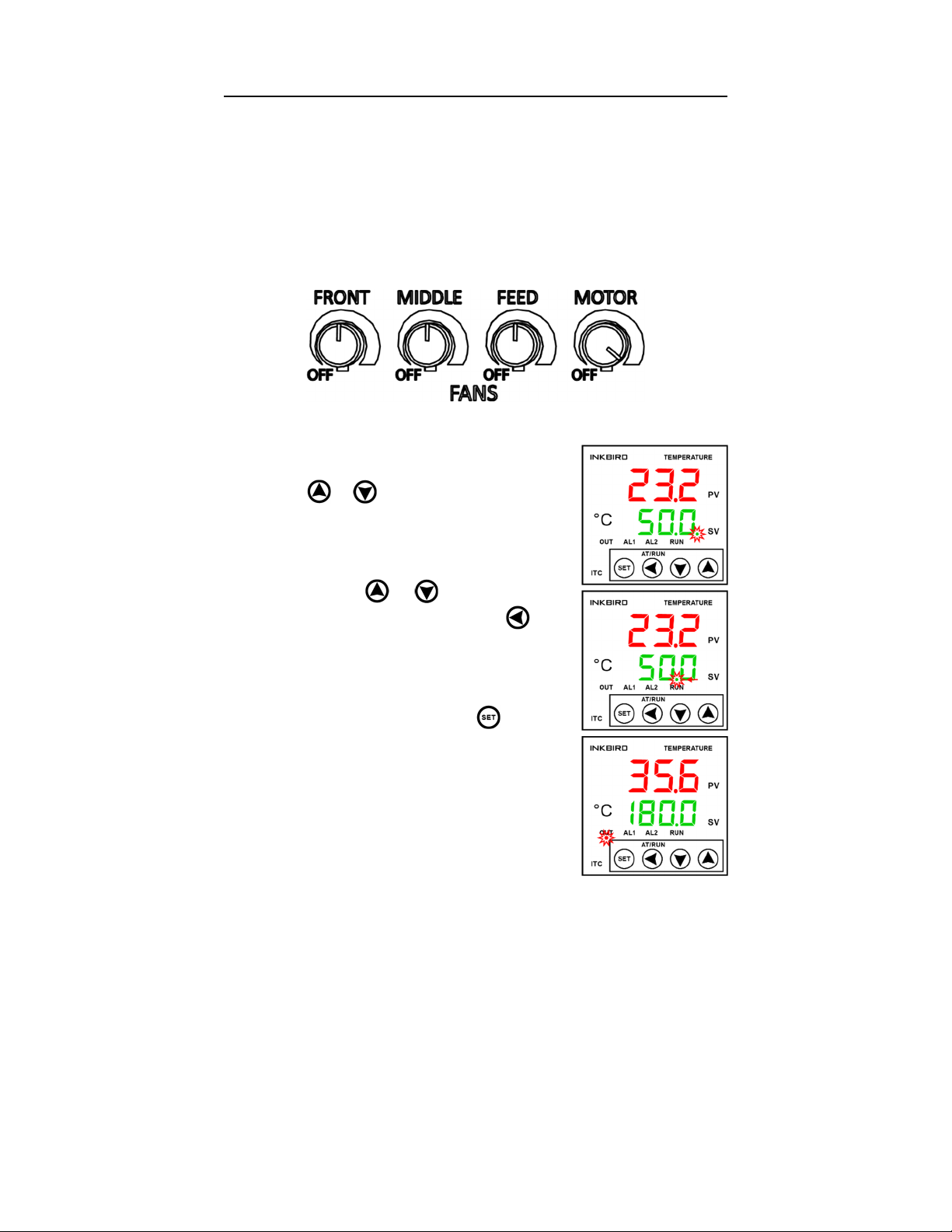
4. Set the Fans to these recommended base settings:
5. Set the PID controllers to within ±30°C of your expected operating
temperatures.
a. To program the set temp, press the
or key once, and the decimal
point will flash at the first selected
digit:
b. Use the and keys to adjust the
selected digit value. Use the key
to select the next digit:
c. Once the set temp is adjusted to the
desired value, press the key twice
to set the value. The “OUT” indicator
will turn on when power to the
heaters for that zone is switched on:
NOTE: Some smoke caused by remaining oils
from manufacturing is normal during the first
startup. If smoke continues or increases after
tuning, contact Filabot.
6
First Use & Tuning - Self-Tuning PID Function
6. Run the self-tuning PID function on all 4 controllers at the same time.
Be sure the measured temp “PV” is at least 30°C cooler than your
set temp "SV" before starting self-tuning function. Doing this
increases the accuracy of the calculated PID parameters. If
temperatures reach the set temp before self-tuning can be started,
set all temperatures low and turn all fans to full speed until
temperatures decrease. Return set temps to your previous setting,
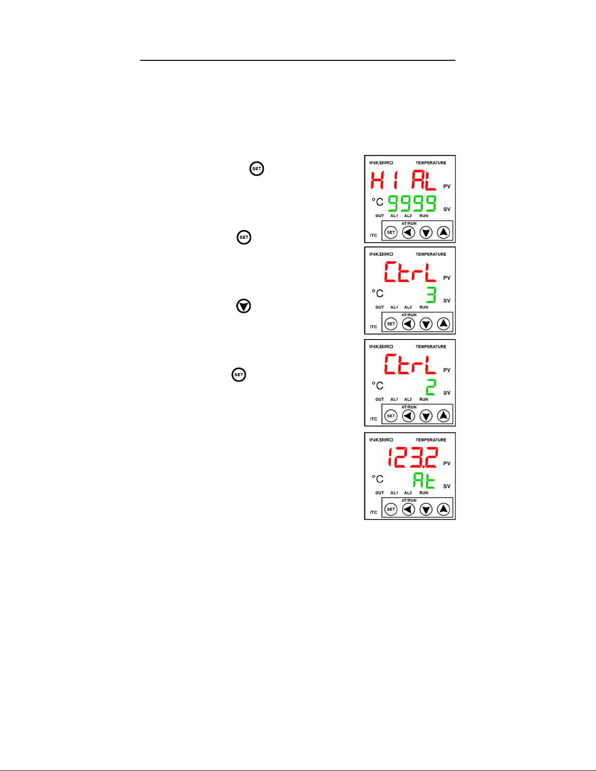
then begin self-tuning the controllers:
a. Hold the key until the display
shows “HI AL 9999”:
b. Press the key 5 times until the
display shows “CtrL 3”:
c. Press the key once to change the
value to “2”:
d. Hold the key to scroll back to the
main display. “PV” will display the
current temp, and "SV" will flash
between “At” and your set temp while
the auto-tuning function is running:
NOTE: While the auto-tuning function is running,
temperatures will overshoot the set temp
significantly. This is normal during the tuning
process which can take around ½ hour. After the
“At” function completes, wait until the temperatures
stabilize at their set temp before beginning to
extrude. To ensure the PID controllers perform at
their highest accuracy, we recommend re-tuning
whenever operating at a temperature more than 30°C higher or lower than
the temperature the previous tune was set at. For advanced users, the full
Inkbird manual can be found on the EX6 page at Filabot.com.

7
First Use & Tuning - Installing the Screw
7. After all the PID controllers have finished auto-tuning, turn the
“SPEED” adjustment knob to the lowest setting (all the way CCW)
and press the “START” button. The “START” button will illuminate.
8. Turn the “SPEED” knob up (CW) slowly until the voltmeter reads
about 10 volts. The motor will turn slowly now. This will allow the
square tang of the screw to align with the square socket at the back
of the barrel.
9. Apply a very thin layer of grease to all 5 flat surfaces of the square
tang on the back of the screw. Be careful not to leave excess grease
on the edges of the tang to minimize grease getting on the barrel
walls while inserting the screw. Check that there is a thin layer of
grease on the square tang at every screw change.
10. Insert the screw, square end first, into the end of the barrel. Push the
screw into the barrel until it stops and begins to turn slowly with the
motor. The tip of the screw should be recessed about 1/2” from the
end of the barrel when the screw is fully inserted.
CAUTION! The barrel is HOT! To prevent burns, always use gloves
when working with the screw and nozzles. Use the provided brass pry
tool or another blunt object to push the screw back.
It should take minimal force to insert the screw fully. DO NOT tap the
screw in as this could jam the screw in the barrel. There could be debris
in the barrel or square socket that is stopping the screw. See “Cleaning”
for more information.
Turn off the machine and contact Filabot if any part of the machine
appears damaged.
11. Apply a thin layer of anti-seize lubricant to the nozzle threads and
screw the nozzle into the end of the barrel. The nozzle should be
snug but not tight, approximately 200 in-lbs (230 kg-cm).

8
Extruding
Even when starting with the recommended settings, adjustments to
screw speed and temperature will be necessary due to variables in the
environment such as ambient temperature and humidity.
1. Set the PID temperature controllers to the expected operating
temperatures. Refer to “First Use & Tuning – Initial Settings” (p. 5).
2. Install the screw. Refer to “First Use & Tuning – Installing the Screw”
(p. 7). NOTE: The screw may be installed at any barrel temperature
however it is recommended that the nozzle is installed at operating
temperature in case of the residual polymer in the threads which
could prevent the nozzle from screwing in fully and sealing.
3. Install the hopper on the feed port and add the polymer pellets to the
hopper. Make sure the slide valve on the base of the hopper is open.
4. Start the extruder and set the speed to about ¼ or 25 volts.
5. Once the polymer begins to extrude from the nozzle, feed the strand
to the spooling unit and begin making fine adjustments.
6. Begin by adjusting the screw speed up to your desired output rate.
This speed may have to be adjusted up or down depending on the
output consistency and how quickly the filament is cooled.
7. Measure the filament at points along its length after it is cool to
determine the consistency of output. If the output is not consistent,
you will see significant variances in the diameter of the filament. If
this is the case, adjustments to screw speed and temperature will
need to be made.
8. When extruder output consistency is within the desired range, adjust
the spooling unit’s speed to control the diameter of the filament.
-Turn up the spooling unit speed to decrease the diameter
-Turn down the spooling unit speed to increase the diameter.
Refer to the Troubleshooting section for general extrusion issues.
Refer to our online resources at Filabot.com for demonstrations of
polymer extrusion and more details on what you should look for with
regards to output.

9
Cleaning
Caution! Parts of the extruder get hot! Wear gloves and eye protection!
It is recommended to thoroughly clean the extruder after use, or right
before the next use, for the most consistent extrusion. Polymer melt on
the screw due to heat creep after shutdown can cause issues when
restarting the extruder. Leave the extruder temperature zones on during
cleaning.
1. Shut off the slide valve on the hopper if pellets are remaining.
Remove the hopper from the feed port. NOTE: Larger pellets can
jam the slide valve from closing all the way however the flow of
pellets will still be cut off, and the hopper can be removed. Have a
container ready to release the pellets into after the hopper is
removed.
2. Either run the extruder until the feed port is empty or use a vacuum
cleaner to remove the remaining pellets. Continue running the
extruder until polymer stops extruding from the nozzle.
3. If you are using a filter nozzle, stop the extruder, remove it, and
replace it with a standard nozzle with a minimum hole size of 1.5mm.
Purge damages the filter. Fill the feed port approximately halfway
with extruder purge compound while continuing to run the extruder.
Do not change the temperatures to run purge. You may need more
or less depending on the polymer used. NOTE: Use high temp purge
for temps over 300°C. It is possible to remove and clean the screw
without using purge material, but the process can be significantly
more difficult and is not recommended.
4. Continue running the extruder until purge stops extruding from the
nozzle, or add more if the residual polymer is still visible in the purge.
NOTE: Running the extruder “dry”
with no polymer in the feed will
cause excess wear on the screw
over time. Avoid running the
extruder while empty for more
than a few minutes at a time.
5. After all the purge has been
extruded, stop the extruder and
remove the nozzle.
6. Use the brass pry tool to push the
screw forward out the end of the
barrel by prying on the screw
flights visible in the feed port.
10
Cleaning - Continued
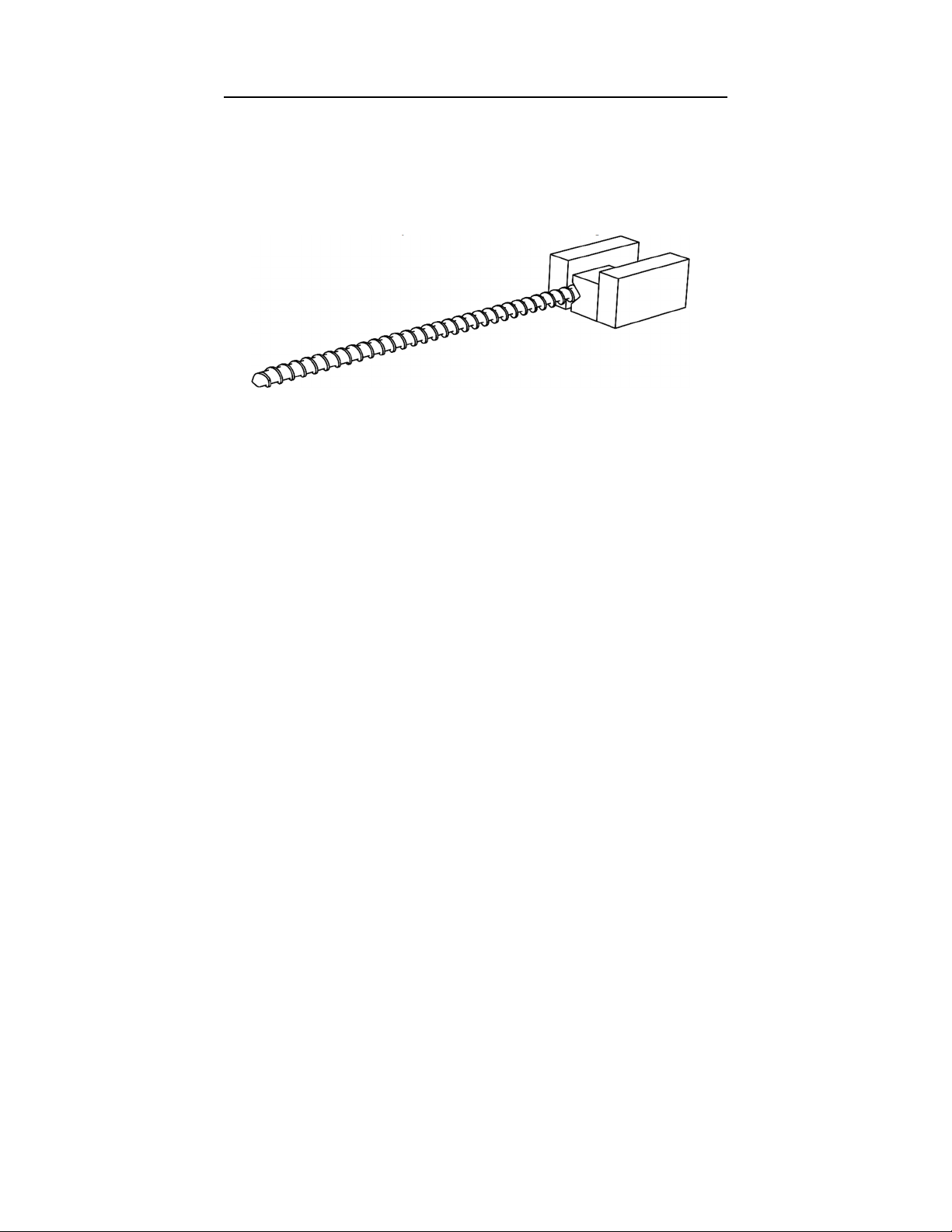
7. Pull the screw the rest of the way out of the front of the barrel using
gloves, then clamp the back of the screw in a non-marring vice with a
v-block for cleaning. NOTE: Clean the screw while it is still hot.
Always use a smooth, non-marring vice and v-block to secure the
screw. Damage to the screw from the use of an improper vice could
cause wear issues or prevent the screw from fitting in the barrel.
8. Clean the remaining material from the screw using a power drill with
the brass bristle wheel. If present, large pieces of material may need
to be scraped off first. NOTE: Always use soft metal tools (brass,
aluminum, etc.) to remove material from the screw to prevent
marring of the surface which can decrease the life of the screw and
cause extrusion issues. Use a heat gun or propane torch if the screw
cools and cleaning becomes difficult.
9. Screw the brass bristle tube cleaner onto the tube cleaner extension
rod and wrap two layers of copper gauze around the brass bristle
tube cleaner (wrap the gauze counter-clockwise with the extension
rod pointing toward you).
10. Secure the end of the extension rod in the power drill chuck and
make sure the drill is turning clockwise.
11. Insert the brass bristle tube cleaner into the end of the barrel, while
spinning, and continue until the end of the tube cleaner is visible in
the feed port. Remove the tube cleaner, while spinning, and repeat if
necessary. Avoid inserting the tube cleaner past the feed port as this
could push debris into the square socket which receives the screw.
12. Use compressed air in the feed port to blow any remaining debris out
the end of the barrel. Check if the barrel looks clean by shining a
light in the feed port and looking into the end of the barrel.
Refer to our online resources at Filabot.com for cleaning demos.
Table of contents
Other Filabot Industrial Equipment manuals


