Filabot Reclaimer User manual

REV.A11‐25‐2019
Filabot
Vermont, USA, Earth
1-802-505-6772
Filabot Reclaimer
Operation Manual
This manual applies to the Filabot Reclaimer.
Triex LLC, Barre, VT 05641, USA
1
CAUTION! Read Carefully
HEAVY Fully assembled Reclaimer weighs 125lbs. DO NOT attempt
to lift or assemble the Reclaimer alone.
SHARP ROTATING BLADES Never operate the Reclaimer with out
all hoppers closed and secured. Never operate the Reclaimer if any
parts appear missing or damaged. NEVER ATTEMPT TO MODIFY
OR BYPASS SAFETY SWITCHES OR CIRCUITRY.
SHARP PLASTIC SHRAPNEL Crushing, cutting, or otherwise
breaking down plastics such as PLA and others will create high
speed projectiles and sharp edges. Always wear proper eyewear and
gloves when working with the Reclaimer and processing plastic.
In Case of Emergency hit the EMERGENCY STOP button or pull
the power cord out of the machine.
Only use the Reclaimer to process thermoplastic polymers. No other
use has been tested or approved by Filabot.
Always STOP the Reclaimer before opening the hoppers.
The Reclaimer is designed for indoor use only. Operate in a clean,
dry area.
Check the AC input voltage specified on the S/N Label near the
power inlet. Only use the specified input voltages to operate the
Reclaimer or damage to the components will occur.
Do not use this device if any parts appear missing or damaged.
Do not modify this device without authorization from Filabot.
Contact Filabot with any questions
1-802-505-6772

2
General Specifications
Power Input: 115VAC-10A or 230VAC-6.5A 50/60Hz 1-phase
1550W MAX - varies with settings
Input Connector Type: IEC 320-C14
Weight: 57kg (125 lbs)
Overall Dimensions:
Drive Control: 230V 3-phase Variable Frequency Drive
4.2A Motor Current Limit
Jam Detection and Automatic Reversing
Drive Motor: 1HP 230V 3.2A 3-phase
62Hz 1780 RPM
Inverter duty
Final Drive: 20:1 Worm gearbox into
2.5:1 #50 roller chain
Final Drive Output: 35 RPM
216 ft-lbs (Calculated)
Shredder: Rotating Blades: 0.25” Wide A2 Hardened Steel
Fixed Blades: Reversible 0.50” 4140 Steel Plate
Granulator: Rotating Drum: 0.20” x 0.20” Cutting Teeth
17-4 SS Hardened
Fixed Blades: Reversible 0.50” 4140 Steel Plate
3
Parts Included
1. Reclaimer Main Body
2. Motor Base Assembly
3. Shredder Hopper
4. Granulator Hopper
5. Shredder Hopper Gas Spring Assembly
6. Granulator Hopper Gas Spring Assembly
7. (2) 5/16”-18 x 7/8” Hex Head Bolts
8. (2) 5/16” Washers
9. (4) 3/8”-16 x 1” Hex Head Bolts
10. (4) 3/8” Split Lock Washers
11. (20) Plastic Drawstring Bags 10" Wide, 14" High
12. Main Bearing Tool
Tools Required:
9/16” Wrench
1/2” Wrench
#2 Philips Screw Driver
Rigid table capable of supporting at least 200lbs
Call 1-802-505-6772 or visit Filabot.com for additional/replacement parts
4
Assembly
WARNING: Fully assembled Reclaimer weighs 125lbs. DO NOT attempt
to lift or assemble the Reclaimer alone.
Two people are required to assemble the Reclaimer.
Assemble the Reclaimer on a rigid table capable of supporting at least
200lbs. If such a table is not available, assemble and operate the
Reclaimer on the floor.
WARNING: The Reclaimer Main Body tips easily when not attached to
the Motor Base Assembly. Someone must steady the Reclaimer Main
Body while assembling it to the Motor Base Assembly.
1. Loosen the 4 motor base bolts using a 1/2” wrench. Do not remove
the bolts.
2. Line up the motor shaft with the gearbox
input on the Reclaimer. Use a pair of
pliers to hold the shaft key from sliding
back while inserting the shaft. Caution!
Reclaimer can tip over easily. Have
someone support the Reclaimer while
attaching the motor.
5
Assembly
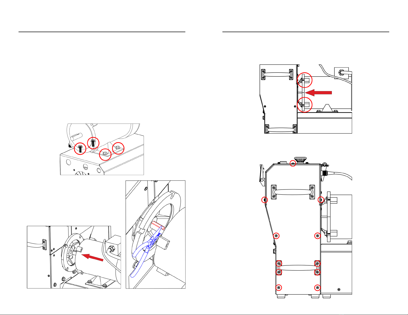
3. Push the motor face flat against the gearbox face. Make sure there is
not gap between the motor face and gearbox face. Install the (4)
3/8”-16 x 1” motor bolts with lock washers and tighten them using a
9/16” wrench.
4. Remove the (7) highlighted panel screws and (4) handle screws with
a #2 Philips screwdriver and remove the Reclaimer right side panel.

6
Assembly
5. Behind the Reclaimer side panel and below the gearbox, install the
(2) 5/16”-18 x 7/8” lower drive enclosure bolts with washers and
tighten using a 1/2” wrench. The motor base enclosure may need to
be shifted under the motor to allign the holes.
6. Reinstall the panel and (7) highlighted panel screws and (4) handle
screws and handle which were removed in step 4.
7. Using a 1/2” wrench, tighten the (4) base bolts which were loosened
in step 1.
8. Remove the inner cotter pin from the hopper hinge and slide out the
rode while removing the aluminum spacers and plastic washers.
7
Assembly
9. Remove the (4) top panel screws using a #2 Philips screw driver.
Line up the two gas spring assembly brackets with the holes in the
top panel as shown and reinstall the screws. Be sure the square
cutouts in the gas spring assembly brackets match with the sensor
cutouts on the top panel.
10. Set the hoppers on top of the Reclaimer in the orientation shown.

8
Assembly
11. Reinstall the hopper hinge rod, spacers, plastic washers and cotter
pin in the order shown.
12. Remove the nuts from the end of the gas springs not attached to the
bracket on the top panel. One at a time, tip each hopper back and
insert the threaded stud on the end of the gas spring the nut was
removed from into the hole midway up the back of the hopper.
9
Assembly
13. Reinstall the nuts on the gas spring studs on the inside of the hopper
and tighten using a 1/2” wrench.
14. Plug the grey control cable from the back of the drive enclosure into
the bulkhead located on the back of the Reclaimer above the motor
and tighten the thumbnut to secure the connector. Make sure to
allign the notch in the connector with the bump on the inside of the
bulkhead.

10
Controls & Inputs
1. Stage 1 Shredder Hopper – Max part size 3 inches in any dimension
(must fit in 3” sphere).
2. Stage 2 Granulator Hopper – Max material size 1/2 inch.
3. Output hopper.
4. Emergency stop button – Press for emergency stopping only, use
Start/Stop button for normal stopping.
5. Start and Stop button – Press to start the machine, press while
running to stop the machine.
6. Safety Reset button – Press at initial power on or after the E-stop or
hopper saftey switches are tripped to reset the safety circuit.
11
Controls & Inputs cont.
7. DrivestatusindicatorLED.Outputcode:
Solidgreen–Drivepoweron,readytostart
Flashinggreen–Driveoperatingnormally,motorisrunning
Solidred–Safetytrip(SafetyswitchesorEmergencyStop)
Off–Nodrivepower(IfMainPowerisilluminatedandindicatoris
offthensafetycircuitmustbereset.
Flashingred(code8)–(8flashesfollowedbypause)Overcurrent
detection,checkReclaimerforjam.Toresetovercurrentdetection,
powerofforhitEmergencystopandwaituntilindicatorLEDturns
offbeforepushingtheSafetyResetbutton.
8. Main power switch and main power indicator.
9. Serial Number & Voltage Input Label
10. Power inlet – IEC C14 110VAC

12
Operation
1. Make sure all 3 hoppers are fully closed and latched.
2. Secure the drawstring collection bags to the flanges on the bottom of the ouput
hopper as shown:
3. Plug the power cable into the power inlet on the machine and into a 110VAC
outlet.
4. Turn on the main power switch. It should illuminate if the machine has power.
5. Make sure the E-stop button is pulled up and push the Safety Reset button to
power up the drive. The status indicator should illuminate green if the drive has
powered on.
6. Press the Start/Stop button to start the machine.
7. To begin shredding, place parts with a maximum dimension of 3 inches in the
top of the Shredder hopper. Do not fill the hopper past the bottom of the view
13
window to avoid feed issues in the hopper. During operation you may need to
adjust the bags so they fill completely.
8. At anytime during shredding, or when the collection bag for the Shredder is
full, the Shredder output can be loaded into the Granulator hopper. Press the
Start/Stop button to stop the machine and transfer the output of the Shredder
into the Granulator hopper.
NOTE: It is recommended to screen the output of the Shredder to remove
material smaller than 1/4 inch before transfering it to the Granulator. This
reduces over granulating of smaller material to help make sure final granule
size is as consistent as possible.
9. Replace the drawstring bag on the Shredder output and press the Start/Stop
button to begin granulating. If granulated material consistency is not
satifactory, it can be screened and run through the Granulator again.
NOTE: Material can be loaded into both hoppers while running allowing for
simultainious Shredding and Granulating.

14
2019,TriexLLC,BarreVT,USA.Nopartofthismanualmaybecopied,stored,transmitted,or
otherwisereleasedwithouttheexpresswrittenconsentofTriexLLC.Thismanualappliesonlyto
theFilabotEX6.WhileTriexLLChasappliedallpossiblecautioninproducingthismanual,weurge
thecustomeroruserofthisdevicetocontactTriexLLCwithanyquestionsorconcernsabout
operation,beforeoperatingthedeviceormakinganyadjustments.TriexLLCprovidesno
assuranceofapplicabilityoftheproducttocustomers'requirements.
Table of contents
Other Filabot Industrial Equipment manuals


