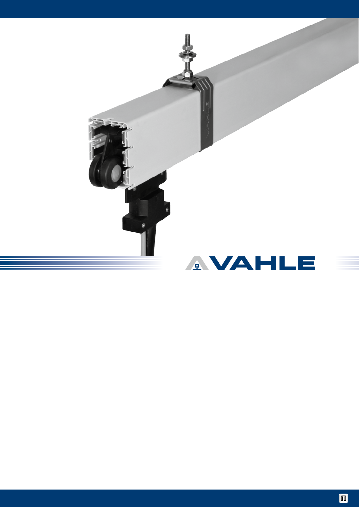
MKHF | MKHS Montageanleitung Mounting instructions
Schleifleitungen montieren
• Beachten Sie vor der Montage den anla-
genspezifischen Verlegungsplan und die
mitgeltende Anlagendokumentation.
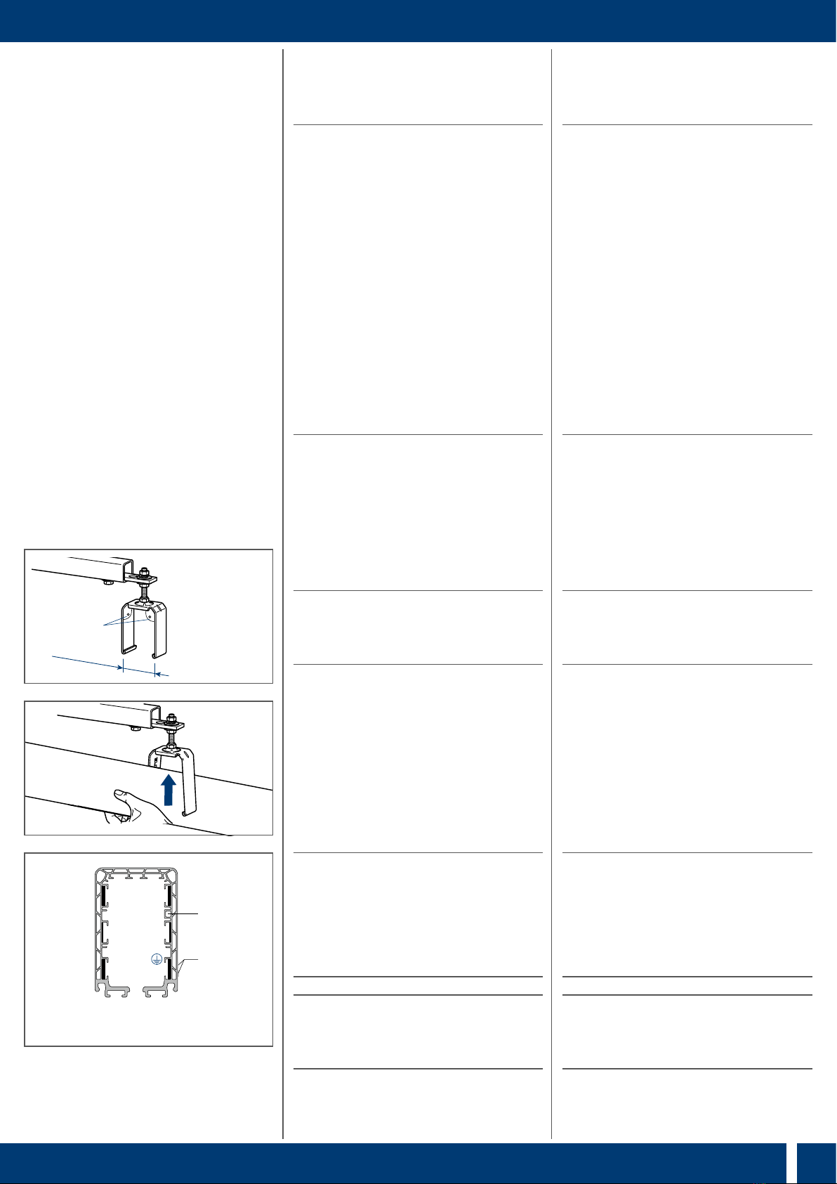
• Stromschienen so anordnen, dass der
Sicherheitssteg bzw. die Kennzeich-
nungsstreifen () zur Kranbahn hin aus-
gerichtet ist.
• Kurven- und Weichenstücke der Schleiflei-
tung, falls im anlagenspezifischen Ver-
legungsplan vorgesehen, immer zuerst
montieren.
• Die Aufhängeabstände für Bögen und
Weichen sind im anlagenspezifischen
Verlegungsplan aufgeführt.
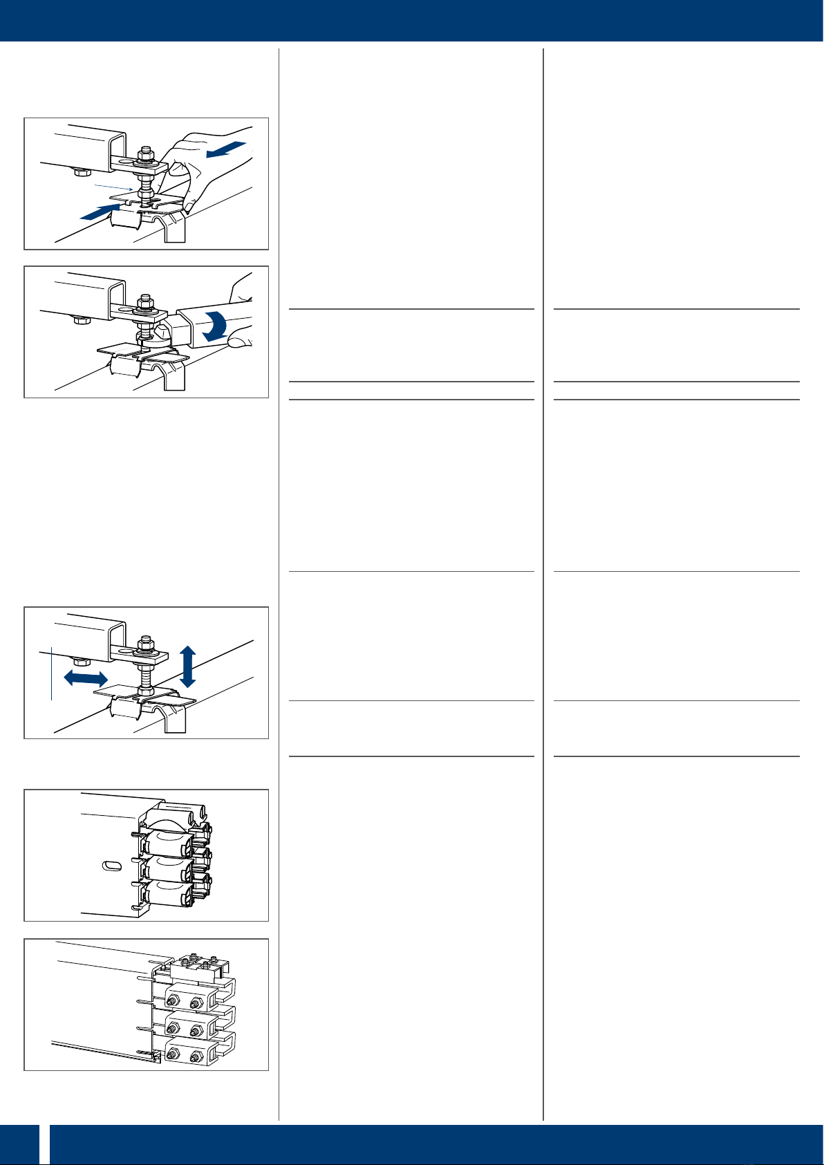
• Bei der Befestigung an den Konsolen
dürfen die Gleitaufhängungen nicht ver-
kanten, damit sich die Schleifleitung frei
bewegen kann.
Beachten Sie die folgenden Montage-
abstände für Stromschienen:
Aufhängeabstand:
• max. 2000 mm für Innenanlagen und
überdachte Außenanlagen mit einer Um
-
gebungstemperatur bis °C.
• max. 1333 mm für Außenanlagen, spez.
Innenanlagen mit hohen Umgebungs-
temperaturen (>–°C) und Anlagen
mit Beheizung.
• Die letzte Aufhängung max. 500 mm vom
Teilstückende anbringen.
• Die Abstände zwischen Gleitaufhän-
gungen, Verstärkungsklammern, Ver-
bindungsmaterial, Endkappen, Einspei-
sungen usw. muss mindestens mm
betragen, um die Materialausdehnung
nicht zu behindern (vgl. Allgemeiner Ver-
legungsplan, S.).
• Schleifleitungsstöße durch Gleitauf-
hängungen mechanisch entlasten. Alle
Aufhängungen stoßentlastet mit einem
Abstand von mm bis max. mm
zwischen Stoß und Aufhängung montie-
ren (vgl. Allgemeiner Verlegungsplan,
S.).
HDie Schleifleitungen müssen sich vom
Festpunkt aus ungehindert ausdeh-
nen können. Zur Erleichterung der
Montage kann das erste Teilstück
mit einer Festaufhängung festgesetzt
werden. Diese Aufhängung muss
nach Beendigung der Montage als
Gleitaufhängung ausgeführt werden.
Installation of powerails
• Before installation, please observe the
plant-specific installation drawing and
the additionally applicable documenta-
tion.
• Arrange the conductor rails such that the
safety web () faces the machinery track.
• Always install curves and switches of
the conductor systems first if planned in
the plant-specific installation drawing.
• The hanging distances for curves and
switches are listed in the plant-specific
installation drawing.
• During fixing to the support brackets, the
sliding hangers must not cant, so that
the conductor systems can move freely.
Please observe the following mounting
distances for conductor rails:
Hanging distance:
• max. support distance 2000 mm for in-
door and roofed outdoor installations
with a ambient temperature upto °C.
• max. 1333 mm for outdoor installations,
special indoor systems with high ambient
temperatures (>– °C) and systems
with heating
• Attach the last hanger max. 500 mm away
from the end of the section.
• The distances between the sliding hang-
ers, the stiffener clamps, the connect-
ing material, end caps, feed elements
etc., must be at least mm, so as
not to impair material expansion (cf.
General installation drawing, page ).
• Mechanically relieve conductor systems
joints by means of sliding hangers. Mount
all hangers with relieved joints with a
distance of mm to max. mm
between joint and hanger (cf. General
installation drawing page ).
H
Free expansion of the conductor sys-
tems away from the fixpoint must be
possible. Provisionally anchor the
first conductor systems section with
the two fixpoint hangers to facilitate
the further mounting procedure. The
fixpoint hanger must be replaced by
a sliding hanger after system instal-
lation has been completed.