FILTRINOV MX User manual

EN
Installation and operating instructions.
Read carefully and retain for future reference.
MX RANGE
SELF-CONTAINED SINGLE-PIECE
FILTRATION UNIT

22
CONTENTS
Recommendations
Technical description of the filtration unit
Installing the filtration unit
Filtration unit power supply
LED Light
Setting the timer
Starting the filtration unit
Pool-Earth
Filtration : Operating principle
Vacuum point for manual suction cleaner
or hydraulic automatic cleaner
Optional BY-PASS
Optional CCS
Optional Salt chlorinator
Optional Salt chlorinator + pH Ctrl + BY-PASS
Optional Chlorinator + pH Ctrl
Winterising and pump disassembly
FAQ/Trouble shooting
1
2
3
4
5
6
7
8
9
10
11
12
13
14
...................................................................... P.3
................... P.4
..................................................... P.5
................................................... P.6
............................................................................................. P.7
............................................................................ P.7
....................................................... P.8
.......................................................................................... P.8
............................................. P.9
................ P.10
......................................................................... P.11
................................................................................... P.12
......................................................... P.12
......... P.13
............................................ P.13
............................. P.14
.............................................................. P.16
15
16
17

EN
- These installation instructions are an integral part of the product and must be given
to the user. This booklet should be retained for reference.
- Check the condition of the contents after unpacking the filtration unit.
- Before wiring up the unit, make sure the manufacturer’s data is compatible with the
planned system and does not exceed the maximum permitted limits of the particular
item.
- Always cut the electrical power from the main consumer unit before carrying out any
maintenance, handling or repair work.
Any repair work must be carried out by an authorised technical support service using
only OEM spare parts. Failure to comply with the above requirements may cause un-
safe operation of the filtration unit and will void the manufacturer’s warranty.
A high-sensitivity, 30 mA cut-off device must be fitted at the head end.
TERMS AND CONDITIONS OF DELIVERY :
All items, including when sold postage and packing paid, are transported at the
consignee’s risk. The consignee must record any reservations regarding damage in
transit in writing on the CARRIER’S delivery note and provide confirmation thereof
within 48 hours by registered letter sent to the CARRIER.
VOLTAGE: before operating, check that the appliance voltage indicated on the data
plate is the same as the mains voltage (usually 230 Volts AC).
FOREWORD :
Thank you for purchasing this MX 18/25 filtration unit and for your trust in our com-
pany. You can rest assured that every effort has been, and will continue to be made to
bring you complete satisfaction. This product has been carefully designed with your
safety in mind.
Your new filtration unit comes with the same features as a traditional filtration system.
Reminder : a residual current device (maximum 30 mA) must be fitted upstream, and
manually tested, as a safety measure to cut the low-voltage power to pool appliances.
RECOMMENDATIONS
TO PREVENT WATER INGRESS INTO THE NON-WATERTIGHT TANK OF THE MX UNIT
WE ADVISE YOU TO INSTALL A DRAIN ALL AROUND THE POOL THAT RUNS INTO A
RELIEF WELL CONTAINING A BASEMENT SUMP PUMP.
• CLEAN BOTH CARTRIDGES AT REGULAR INTERVALS
• ALWAYS LOCK THE LID SHUT AFTER COMPLETING MAINTENANCE WORK IN
THE TANK
• DO NOT USE FLOCCULANTS OR «MULTIFUNCTIONAL» CHLORINE
1
24
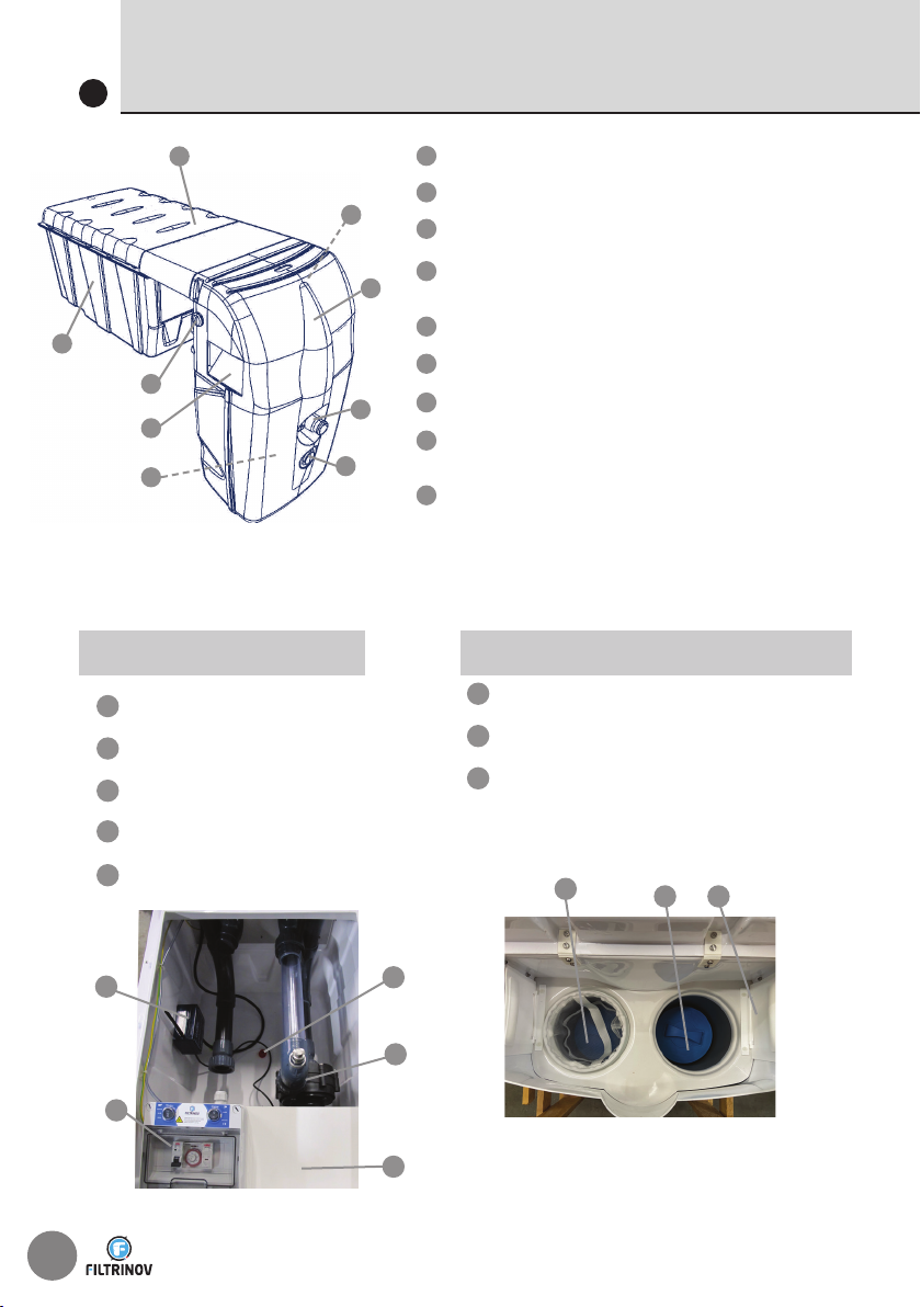
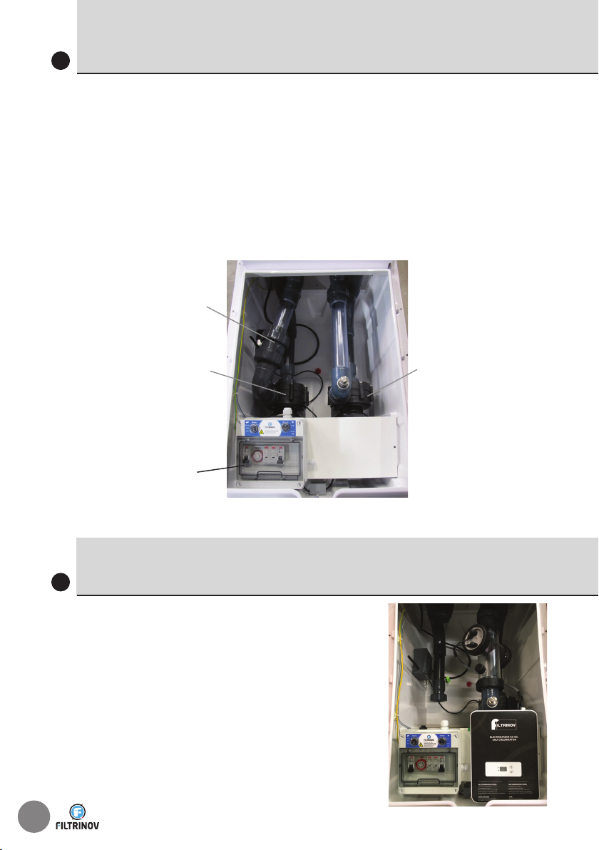
TECHNICAL DESCRIPTION OF THE FILTRATION UNIT
2
3
3
6
6
8
8
9
9
2
2
5
5
7
7
1
1
4
4
Filter access lid.
Multi-directional, high-flow nozzle.
LED light.
Dual filter cartridge housing incl.
2 leaf baskets.
Two suction skimmers.
Massage function air-flow control.
Counter-current system switch (pneumatic)
In-ground section containing :
Pumps/Control panel/Optional items.
Removable lid with mechanical lock
3
3
2
2
1
1
4
5
Filter pump
Control panel
Pool light transformer
Water drain opening
Remote control unit
3
2
12 Leaf baskets
2 Filter cartridges
2 Skimmers
IN-GROUND SECTION SUBMERGED SECTION
5
2
1
4
3

EN
INSTALLING THE FILTRATION UNIT
3
• Dig a pit into which the filtration unit tank will be placed.
• Remove the filtration unit from its packaging and place it carefully in
position straddling and resting on the pool structure.
• Make sure the front, pool-side of the unit is positioned fully perpendicular
to the pool wall.
• Feed in the electrical wiring and then fill in the pit with gravel all around
the filtration unit tank.

26
FILTRATION UNIT POWER SUPPLY
4
The filtration unit should be connected to an insulated electricity
supply running directly from the main consumer unit with a 16A fuse
or circuit-breaker, protected by a 30mA RCD (not included).
Use a 3-wire cord, earth-live-neutral, with a 1.5 or 2.5 mm² section if
less than 30 linear metres.
Marlanvil
92.08
0
I
Auto
1
2
3
4
5
6
7
8
9
10
11
12 13 14
15
16
17
18
19
20
21
22
23
24
KM1
POWER
PUMP
TRANSFO
KM2
CCS
WP3/M
3P Movable female
connector
WP3/H
3P Movable male
connector
WP3/M
3P Movable female
connector
WP3/M
3P Movable female
connector
WP2/M
2P Movable female
connector
PH PUMP
PRESSURE SWITCH
WP2/H
WP3/H
WP3/H
WP3/H
WP3/M
WP3/H
WP3/M
WP3/M
WP3/H
WP2/H
WP3/M
Connecteur mobile
femelle 3P
CHLORINATOR
WP3/H WP3/M
|
||
O
|
O
Q1
C 2A
3kA
KM1
78 1 2 3
L N
0
I
Auto
KATS11B
1
2
3
4
5
6
7
8
9
10
11
12 13 14
15
16
17
18
19
20
21
22
23
24
V1
PGR07
Filtration pump
0.75kW 5A max
Lighting
transformer
Earth connection
Front-mounted filtration and lighting controls
LN
PE
PE
N L
N L
WP3/HEM
3 P Flush-mounted socket
connector
ower supply 230V 50-60Hz Use a 30mA
+ differential protection system
A C16 thermal magnetic circuit breaker
WP3/M
3P Flush-mounted male
connector
WP2/M
2 P Flush-mounted
male
MX panel with options
MX panel without options
A detailed wiring
diagram is
included in the
control panel

EN
LED LIGHT
5
Your filtration unit includes a light
as standard.
A MULTICOLOUR LED light option
is also available in 11 non-animated
colours incl. white and with 5
sequence programmes (remote
control included)
(Manufacturer’s guide included)
Standard
Optional
SETTING THE TIMER
6
• Continuous mode ( 24-hour filtration)
Move the filter switch on the outside of the electrical panel to
«Manual».
• Auto mode (timed filter operation)
Move the filter switch on the outside of the electrical panel to
«Automatic».
Turn the clock hands to set the exact time relative to the pointer
(triangle) on the right of the clock.
Push the segments outwards to set the scheduled «On» times.
Sequencing principle:
Minimum 1 h of downtime after 4 h of operation.
> See the instructions attached to the panel
28
POOLEARTH FUNCTIONAL EARTH
8
It is vital that the pool be earthed in order to
remove stray currents from the water.
Stray currents are not dangerous to people, but
they do electrolyse the metal components in
the pool, which increases corrosion. They can
also disrupt the treatment probes, resulting in
incorrect amounts of product being injected.
This is why FILTRINOV has included a pool earth
with these products. Screw it into the threaded
attachment point provided and connect it to
the earth rod with a Ø 6 mm copper braid earth
strap (parts not included).
A hole will have to be drilled in the tank to route
the braid through the packing gland provided.
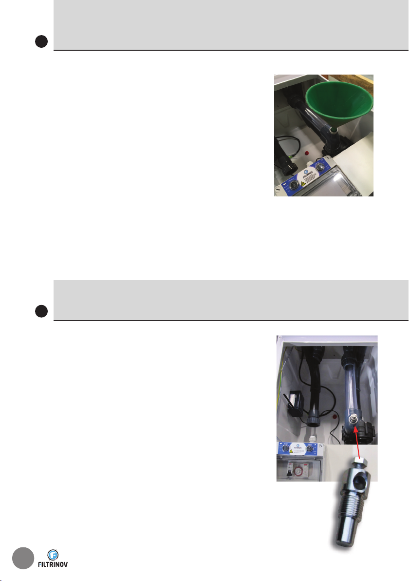
STARTING THE FILTRATION UNIT
7
When the water in your pool is at
of the level of the skimmers, operate the
filtration unit for the first time as follows :
1. Prime the pump by filling it with water
through the hole provided
2. Screw in the Pool earth
3. Put the filtration unit in manual mode to start
the pump
You are strongly advised to unscrew and remove the drain plug from
the tank when you have finished installing the filtration unit.
Repeat the above steps if the priming procedure is not working
after 2 minutes.

EN
FILTRATION : OPERATING PRINCIPLE
9
Water from the surface of the pool is drawn in by the skimmers and
sent through the filter cartridges, where it is cleaned. It then travels
on to the pump, which discharges it through the return nozzle back
into the pool.
The filter cartridges must be washed every few complete filtration
cycles.
The cartridge should be cleaned at least once a week and whenever the
suction cleaner has been used. To clean the cartridge, remove the basket,
lift out the cartridge and gently hose it down. Refit the cartridge once it is
clean.
Your MX includes a cartridge housing at the bottom of the filter holder to
fit the cartridge. Turn the cartridge a quarter turn downwards to slot it into
place in the filter holder. Remember to fit the basket and its pre-filter.
All FILTRINOV filtration units are checked and tested with the utmost care
and subject to FILTRINOV’S stringent quality controls.
The use of non FILTRINOV-approved parts and consumable items shall
render the pump and hydraulic system warranty void.
EASYFILTER bags and cartridges are not approved by FILTRINOV.
Persistent clogging and risk of permanent damage to the pump.
The filtration time should be increased as the water temperature rises :
12° to 16° = 6 hours
16° to 24° = 8 hours
24° to 27° = 10 hours
27° to 30° = 12 to 14 hours or more
Sequencing principle : Minimum 1 h of downtime after 4h of operation.
30
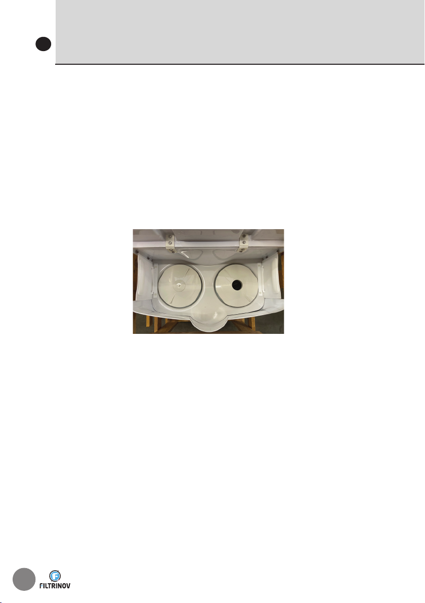
VACUUM POINT FOR MANUAL SUCTION CLEANER
OR HYDRAULIC AUTOMATIC CLEANER
10
• Connect one end of the hose to the suction cleaner ;
• Hold the suction cleaner by the handle and insert it into the pool ;
• Gradually insert the hose into the water until the water pushes out
the air (tip : you can fill the hose with water by placing its tip in front
of the return nozzle with the unit running) ;
• Feed the other end of the hose into the skimmer mouth and attach
it to the skim vac plate that seals off the basket ;
• Place the other (plugged) skim vac over the other basket in order to
block suction from the second skimmer and maintain best cleaning
performance ;
• Only use when using the suction cleaner.
The cartridges should be cleaned at least once a week and whenever
the suction cleaner has been used. To clean the cartridges, remove the
baskets, lift out the cartridges and gently hose them down. Refit the
clean cartridges and the baskets.
EN
OPTIONAL BY-PASS (3-way valve)
11
The by-pass consists of a 3-way valve and a branch Tee.
You are advised to seal the pipe entries in order to prevent water
getting into the tank.
Your heat pump is connected to the filtration unit by a Ø 50 PVC
pipe.
• Place the 2 shutoff valves at the inlet and outlet of the heat pump
so that it can be isolated during winter storage.
TO POOL RETURN
TO HEAT PUMP
32
SALT CHLORINATOR
13
Consists of a cell and a chlorinator
controller.
Read the accompanying settings, operating
and maintenance guide.
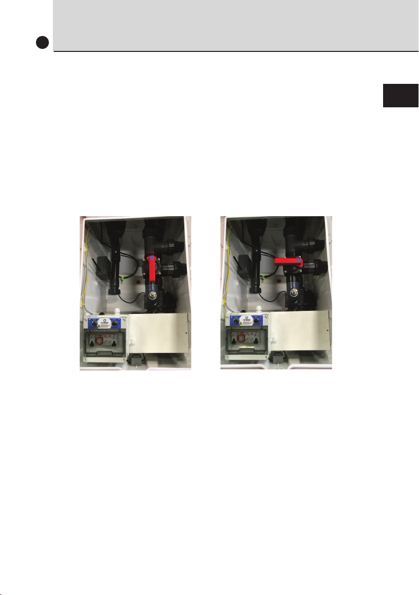
OPTIONAL COUNTER-CURRENT SYSTEM (CCS)
Counter-current system pipework :
12
• To switch on the counter-current system, press the pneumatic
push-button located on the side of the underwater section.
• To stop the counter-current system, press the push-button
again.
Non-return
valve
CCS
pump
Filtration + CCS
control unit
Filtration
pump

EN
BY PASS + CHLORINATOR + PH CONTROL
CHLORINATOR + PH CONTROL
14
15
• Chlorinator consists of a cell and a
chlorinator controller.
• The pH controller consists of a peristaltic
pump, a probe sensor, and an injector.
It is strictly forbidden to store pH
containers inside the tank.
Read the accompanying settings, operating and main-
tenance guide.
• The by-pass consists of a 3-way valve and a branch Tee.
You are advised to seal the pipe entries in order to prevent the
ingress of water into the tank.
• Chlorinator consists of a cell and a chlorinator controller.
• The pH controller
consists of a peristaltic
pump, a probe sensor,
and an injector.
We recommend a covered
inspection pit (not provided)
next to the tank for storing
the container.
TO POOL RETURN TO HEAT PUMP

34
WINTERISING & PUMP DISASSEMBLY
16
An actively winterised pool continues to operate at a slower than normal
rate throughout wintertime.
This is the recommended winterising procedure in less cold regions. If you
live in a harsher winter climate, you should choose to passively winterise
your pool instead.
• First clean the pool structure, the water line, basket and cartridge.
• Next, shock the pool with chlorine.
• Run the filtration system non-stop for at least 12 hours.
• Then reset your timer to run the filtration system for 30 minutes
every 3 hours (do not be afraid to increase the running time if the
temperature is significantly below zero).
• Your pool will not require any more product treatments for the
whole winter. Just monitor the water’s pH level and adjust if
necessary.
• Check and clean the basket and cartridge at regular intervals.
• We also recommend that you use winter floats in your pool.
• You can also cover your pool with a winter cover or tarp although
this is not mandatory.
Passive winterising involves shutting down the filtration unit entirely.
• First clean the whole of the pool and its equipment
(floor and walls, water line, baskets, cartridges, etc).
• Check the water’s pH level and adjust if necessary.
• Shock the pool with a chlorine treatment.
• Run the filtration system non-stop for at least 12 hours.
• Protect the filtration system from frost.
• Active Winterising :
• Passive winterising and pump disassembly :
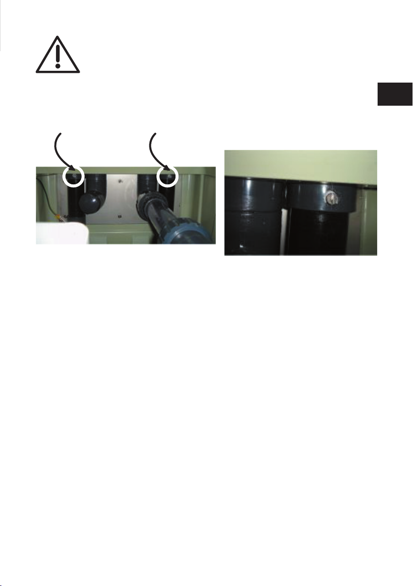
EN
• Undo the 2 bleed screws to drain the water from the pipes and
prevent a siphon forming.
• Unscrew the pump inlet and outlet unions.
• Wait for the water to drain through the hole in the bottom of the
tank.
• Disconnect the 3 pump wires from the electrical panel.
• Lift the pump out of the unit, taking care to keep the two small pins
and the foam underneath the pump.
• Store the pump and the cartridges in a dry place (e.g. Garage, etc)
• We also recommend that you use winter floats in your pool.
• You can also cover your pool with a winter cover or tarp, although
this is not mandatory.
When reassembling, remember to refit both bleed screws to the
piping, otherwise you will not be able to prime the pumps.
CAUTION : ALWAYS CUT THE ELECTRICAL
POWER UPSTREAM OF THE FILTRATION UNIT
FIRST
36
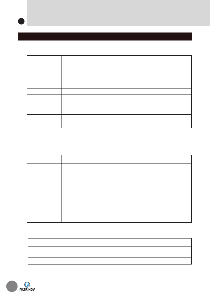
CAUSE SOLUTION
Cartridges
• SITUATION 1: The cartridges are dirty but not clogged. Clean the cartridges at more regular intervals (once every fortnight)
•SITUATION 2: Renew the cartridges if they are clogged
•SITUATION 3: If you are using a flocculent or anti-algae treatment, lower the water level by 20 cm and renew the cartridges
Leaf baskets Clean the debris from the baskets at regular intervals and clean or renew the Netskims (skimmer socks/nets)
Pump Clean the pump housing to remove any foreign matter and unblock the turbine
Water level Check the water height, making sure it is ¾ of the way up to the skimmer niches
Priming
•Check that the pump has been primed properly
•If it hasn’t, remove the delivery system at the pump outlet, fill the pump with water and jolt-start the unit again on and off in
quick spurts (5 seconds on, 1 to 2 seconds off); 3 or 4 times should be enough
Position of the unit
•The 4 contact points on the rear of the side that is submerged in the pool should be hard against the pool wall
•This is only possible if you ensure that the tank section is perfectly horizontal and supported sufficiently high up to avoid strain that
would pull the contact points away from the pool (see the installation guide)
CAUSE SOLUTION
Power supply
•Check the wiring from the pump to the unit’s electrical enclosure
•Check the wiring from the electrical enclosure to the mains power supply
•Check the 30 mA circuit breaker at the line end
Pump switch •Check the wiring to the pump switch
•eplace the switch if it is not working
Front-mounted 3-position
switch (Auto/0/Manual) on
the electrical enclosure
•Put the switch in Manual mode
•If the pump still does not work, check the connections at the wire terminals behind the switch inside the enclosure
•If the problem is still not resolved, contact your retailer to have the switch replaced
Timer
•Check the timer wiring inside the electrical enclosure
•Check that the 3-position switch (Auto/0/Manual) is turned to Auto mode
•Also turn the switch in the bottom left corner of the timer dial face to Auto
•Use the timer segments to set the filtration to start and stop at different periods
•If the filtration does not start, the timer is faulty and will have to be replaced
CAUSE SOLUTION
Turbine Use a large flat-blade screwdriver at the rear and in the centre of the pump to try and release the turbine and get it turning
Condenser Replace the condenser
PROBLEM : Low pressure flow and/or air bubbles in the pumped water flow
PROBLEM : The pump does not start
• If there is no noise:
• If the power unit is making a noise:
TROUBLE SHOOTING
16
FILTERS/PUMPS/CCS

EN
CAUSE
(carry out the checks in the
order shown) SOLUTION
Lighting circuit breaker •Check whether the circuit breaker has been tripped and is still open
•If the circuit breaker has not stayed open, it is not working and will have to be replaced
Front-mounted 2-position (I/0)
switch on the enclosure
•Check that the switch is turned to I
•Check the connections at the terminals behind the switch inside the enclosure.
Transformerr (220V/12V) •Check the transformer’s output voltage (12V)
•If the transformer’s output voltage is zero, it is not working and will have to be replaced.
Remote control system unit
(blue enclosure with a black
antenna, inside the tank)
•Open the housing
•Press the small black button inside the housing; a small red LED next to it should come on
•If nothing happens, the remote control system unit is not working and will have to be replaced
•If the red LED comes on, configure the remote control (see paragraph 6 of the remote control unit instructions)
Remote control
•Open the remote control battery compartment and check for oxidation, etc, the condition of the battery and that it is fitted the
correct way round.
•Configure the remote control (see paragraph 6 of the remote control unit instructions).
•Look at the top of the remote to see whether it comes on when you press the button on the left.
•If nothing comes on, the remote control is not working and will have to be replaced.
Light •If none of the above items are found to be at fault, it is the light that does not work.
•It will have to be replaced using a niche (feed-through) system.
CAUSE SOLUTION
Crystal tube
The crystal tube along the inside the tank has come loose from its pneumatic switch after the side-mounted pneumatic button was
used to start the CCS.
Re-attach the tube.
Timer
• Make sure that not all the timer segments are pushed out, causing the filtration system to run non-stop. If they are, push some
back in to set OFF periods and then try to turn the dial forward in time by hand to an off period in order to stop the filter running.
•If the above step fails to switch the pump off, turn the front-mounted 3-position switch (Auto/0/Man) on the enclosure to 0. The
pump will stop, but the timer is not working and will have to be replaced.
Front-mounted 3-position
switch (Auto/0/Man)
on the electrical enclosure
•Turn the switch to 0
•If the pump is still running, check the connections at the wire terminals behind the switch inside the enclosure.
•If this still fails to switch the pump off, contact your retailer to have the switch replaced, and cut the mains electrical power to the
filter unit.
CAUSE SOLUTION
Overheating power unit
• To prevent the pump and its thermal circuit breaker from overheating, we advise you to programme your filter system to run for no
more than 3 or 4 hours at a time with a 1-hour break between operating periods.
Example : Water temperature: 24°C; required filtration time: 12 hours. We recommend that you programme the filtration unit to work
in stages from 7 am to 10 am then 11 am to 2 pm, 3 pm to 6 pm, and finally from 7 pm to 10 pm.
•We also recommend that you clean the cartridges.
Excessively dirty cartridges significantly reduce the flow of water into the pump, causing it to overwork and overheat.
PROBLEM: The pool light does not come on.
PROBLEM: The pump does not switch off
PROBLEM: The pump cuts out and starts up again later
TROUBLE SHOOTING
16
LIGHTING
38
CAUSE SOLUTION
Light The light is reaching the end of its service life or is not/no longer watertight. Replace the light using a niche (feed-through) system.
PROBLEM: The light is blinking.
TROUBLE SHOOTING
16
LIGHTING
CAUSE SOLUTION
Electrolyser circuit breaker in
the filtration electrical enclosure
•Check whether the circuit breaker has been tripped and is still open
•If the circuit breaker has not stayed open, it is not working and will have to be replaced
Electrolyser unit
If the circuit breaker is working properly but the unit does not switch on, the electrolyser unit is out of order and will have to be replaced.
CAUSE SOLUTION
Electrolyser circuit breaker in
the filtration electrical enclosure
•Check whether the circuit breaker has been tripped and is still open
•If the circuit breaker has not stayed open, it is not working and will have to be replaced
Nano PH pump
If the circuit breaker is working properly but the unit does not switch on, the electrolyser unit is out of order and will have to be replaced.
CAUSE SOLUTION
Electrolyser unit
•Set the treatment system to maximum operating capacity (10 for 100%) for 5 minutes
•Take a voltage reading from the electrolysis cell terminals
•If the voltage reading is between 0V and 2V, there is a problem with the electronics in the electrolyser unit (power board, etc)
Electrolysis cell
•Set the treatment system to maximum operating capacity (10 for 100%) for 5 minutes.
•Take a voltage reading from the electrolysis cell terminals.
•If the voltage reading is higher than 10V, the electrolysis cell is nearing the end of its service life (max. 15 days) or is not working
(above 12V), and will have to be replaced.
Cartridges Excessively dirty cartridges will quickly consume the chlorine that is generated to clean the pool, resulting in an incorrect chlorine
production reading.
PH Level The PH level should be between 7.0 and 7.2 to keep the chlorine at peak effectiveness
CAUSE SOLUTION
Container The pH regulator container may be empty and need replacing.
Suction strainer Check that the suction strainer (plunger in the container) is properly inserted in the container. Often, the container only needs to be
displaced slightly for the plunger to no longer be inserted properly and stop the reducer being injected.
Hose
•The hose from the dosing pump to the container may have drawn in something that is preventing the pH reducer from reaching the pool.
•The hose may also have a hole, possibly caused by the acidity level of the reducer. If so, it will have to be replaced.
•We recommend that you replace the hose at least every two years as the acidity level of the pH reducer will gradually cause it to
become porous.
PROBLEM: The electrolyser unit does not switch on..
PROBLEM: The Nano pH pump does not switch on.
PROBLEM: The electrolyser is producing little or no chlorine.
PROBLEM: The dosing pump is not injecting pH reducer.
AUTOMATIC WATER TREATMENT
EN
TROUBLE SHOOTING
16
CAUSE SOLUTION
No «pool earth» fitted
•A stray current is probably interfering with your probe reading. Use a glass water to check if this is the case:
1. Dip the probe into a glass of tap water (pH level between 7.5 and 8.0) and see if the reading is consistent.
2. Next, dip the probe into a 7.0 reference solution. The reading should be around 7.0. If not, the probe needs to be recalibrated.
3. Next, dip the probe into a glass filled with water from the pool. Since the probe was calibrated properly in the previous step, the pH
level shown will be correct.
4. To finish, put the probe back in its proper place (retaining clamp on the suction line).
• If the reading matches the reading from the glass filled with water from the pool, there is no stray current in the pipes; the probe
was not calibrated properly.
•If the reading does not match the reading from the glass, you will need to install a «pool earth» to the system.
A pool earth is a metal rod placed in slightly damp ground and connected to the terminal provided on the filtration unit line by a
minimum 6 mm² braided connector.
The “Pool Earth” acts as a stray current earthing device.
•We always recommend connecting your system to a “pool earth”.
pH probe
Carry out the glass of water test mentioned above using a 7.0 reference solution. Calibrate the probe using the 7.0 solution and then
dip it into a 10.0 reference solution. If the reading is not 10.0 or thereabouts, the probe is not working properly and will have to be
replaced.
PROBLEM: The pH probe is giving incorrect readings.

This manual suits for next models
2
Table of contents
Other FILTRINOV Water Filtration System manuals


Popular Water Filtration System manuals by other brands

Excalibur Water Systems
Excalibur Water Systems Sureflo SFLC Series Installation and user guide

HATHASPACE
HATHASPACE HSP001 quick start guide

Forbes
Forbes EDGE user manual

VOL
VOL FE-085021 Instructions for use

Brita
Brita MAXTRA PRO Instructions for use

Club Hydrate
Club Hydrate Perfect Pitcher owner's manual


