Page 2
Contents
Technical Specs ......................................................................2Calibraon ......................................................................... 7
Boom Kit Contents .................................................................3Maintenance, Storing and Winter Storage........................ 8
Boom Kit Assembly Instrucons .......................................4 - 5 Boom Kit Exploded View/Parts List.................................... 9
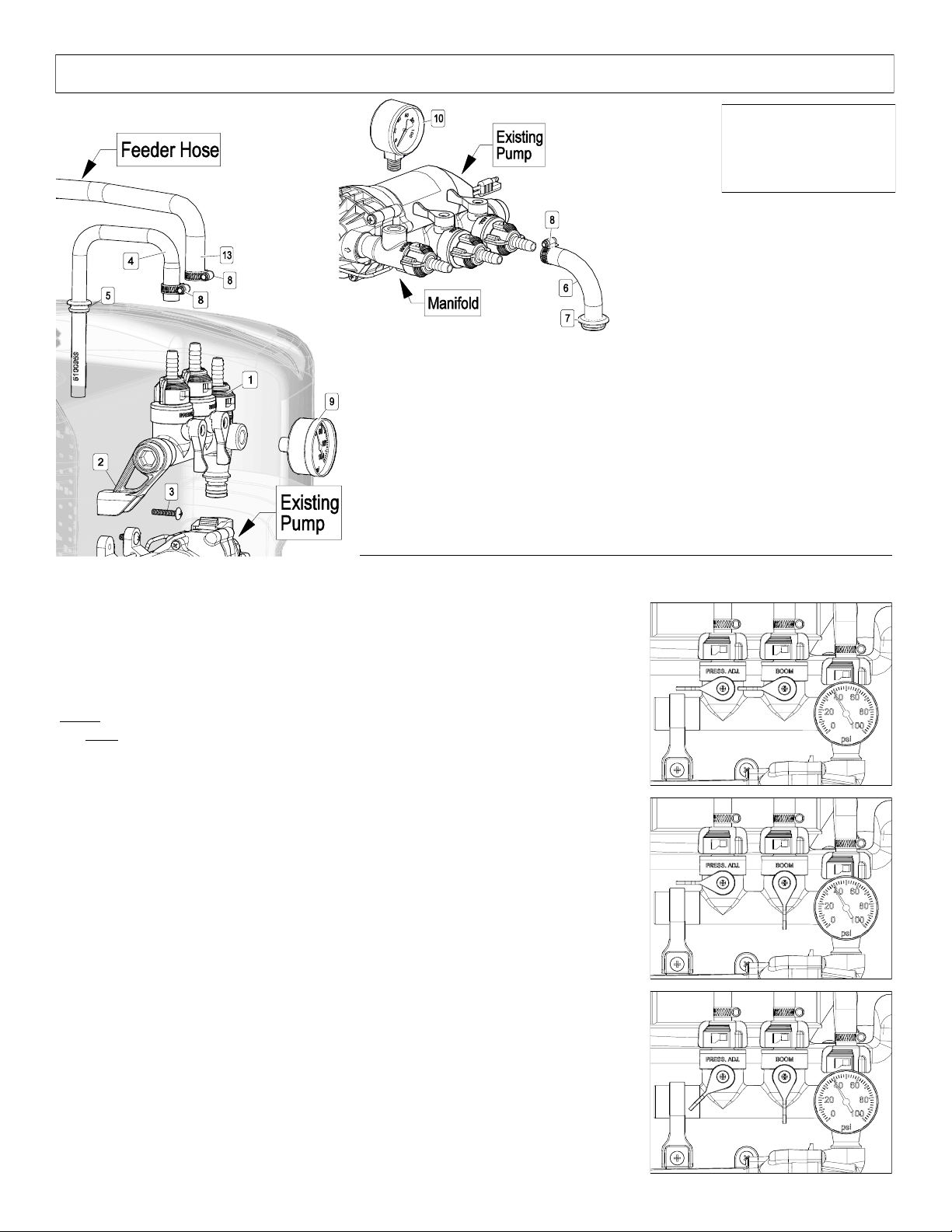
Plumbing Conguraons........................................................6Boom Exploded View/Parts List....................................... 10
Operaon..........................................................................6 - 7 Warranty.......................................................................... 12
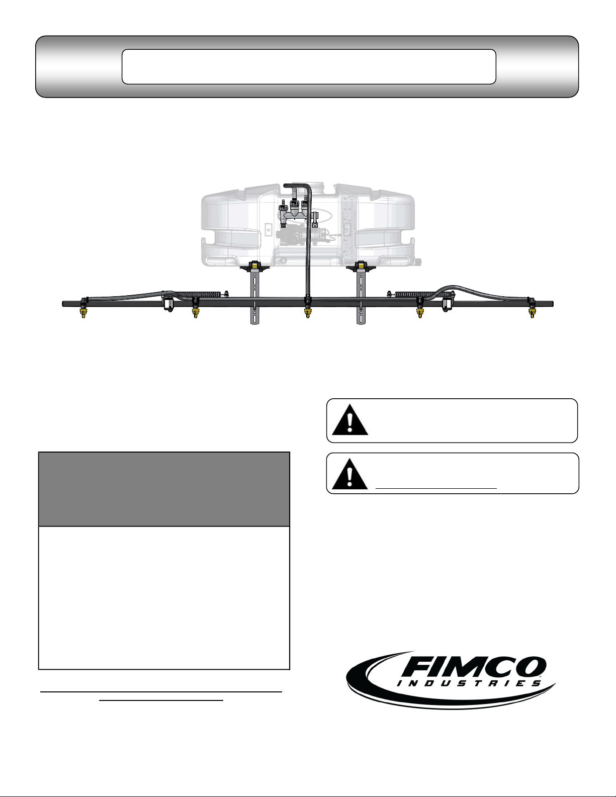
Model: ATVBK-500-QR (5302338)
(5-Nozzle Boom Assembly w/Connecng Fings)
Technical Specicaons
• 5-Nozzle Boom Assembly (100” Spray Coverage)
• Excellent distribuon for uniform coverage along the boom
• Break-Away Outer Booms
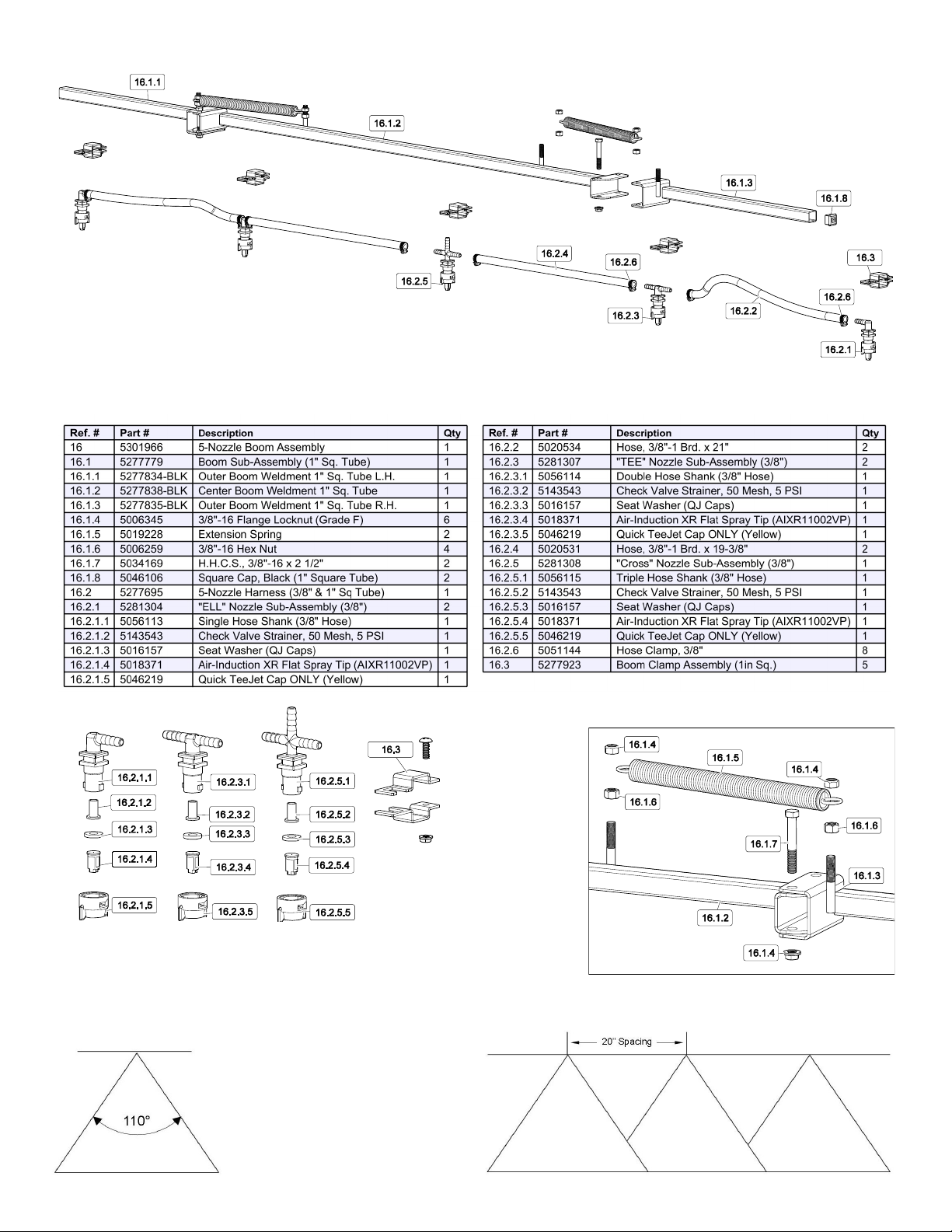
• Corrosion-Resistant AIXR11002VP, #2 (Yellow) 110° ps (**)
(**) These ps provide excellent chemical and acid resistance with an exceponally long wear life.
110° wide tapered, at spray angle with air inducon technology for beer dri management.
Compact size prevents p damage.
• Check Valve Strainers, 50 Mesh, 5 PSI
This boom weighs approx. 23 Lbs.
Always check the vehicle load rang before using a boom with sprayer, ensuring total weight is acceptable.
Do not exceed the recommended rang.
~~~~~~~~~~~~~~~~~~~~~~~~~~~~~~~~~IMPORTANT~~~~~~~~~~~~~~~~~~~~~~~~~~~~~~~~
Remove tank lid and be sure the tank is clean and free of any foreign material. Rinse tank out of any tank residue before lling with
water to test.
~~~~~~~~~~~~~~~~~~~~~~~~~~~~~~~~~IMPORTANT~~~~~~~~~~~~~~~~~~~~~~~~~~~~~~~~
It is VERY important to test the sprayer, aer connecng a boom, with plain water before actual spraying is aempted. This will
enable you to familiarize yourself with the sprayer and check for leaks without the possibility of losing any expensive chemicals.
~~~~~~~~~~~~~~~~~~~~~~~~~~~~~~~~~~WARNING~~~~~~~~~~~~~~~~~~~~~~~~~~~~~~~~~
Read and Understand the Owner’s Manual before using this boom. Test and use in accordance to instrucons.
Read and Follow chemical label instrucons and wear protecve gear when lling, using, cleaning and
servicing the boom.
Exercise Cauon in vehicle handling when towing/hauling a lled sprayer to avoid loss of control or overturning.
Keep Sprayer and Spray materials away from other people, children and pets.
Do Not Turn on Power to the sprayer, unl ready to spray in order to avoid unintenonal spray release.
Do Not Use on steep slopes. A full sprayer could cause loss of control or overturn sprayer and vehicle.
Always operate up and down a slope, never across the face of a slope.
Keep all movement on slopes slow and gradual. Do not make sudden changes in speed, direcons or turning. Do not start or stop
suddenly when going uphill or downhill.
Stop on level ground, set the parking brake and shut o engine before leaving the operator’s posion for any reason.
Keep all parts in good condion and properly installed. Fix damaged or worn parts immediately.
Cauon should be taken when towing and/or using any sprayer. The sprayer combined with the weight distribuon, turning radius
and speed of vehicle can result in damage to vehicle, sprayer and/or boom or severe injury or death, if not used properly.
Improper use or handling of chemicals could result in serious injury or illness, or could cause damage to the environment.