7
10. Instruments
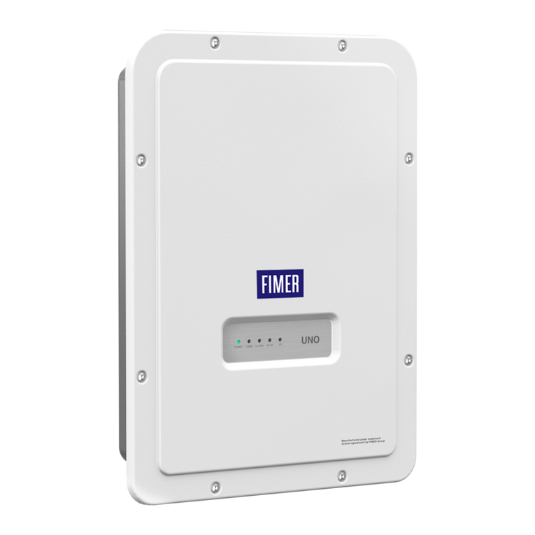
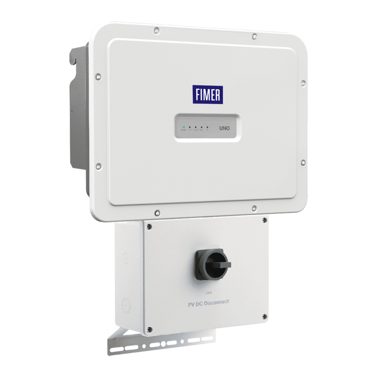
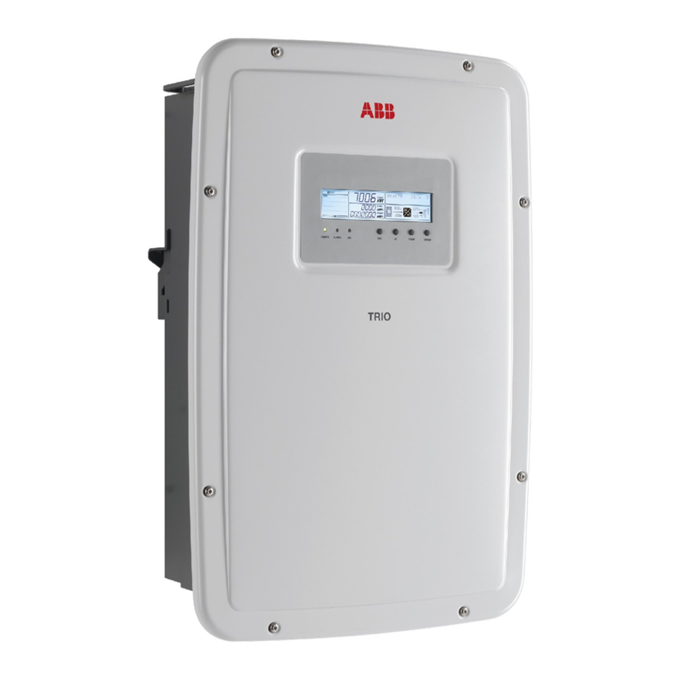
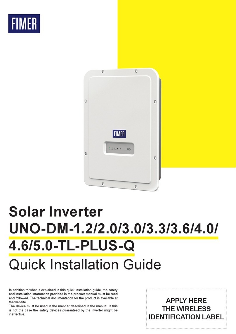
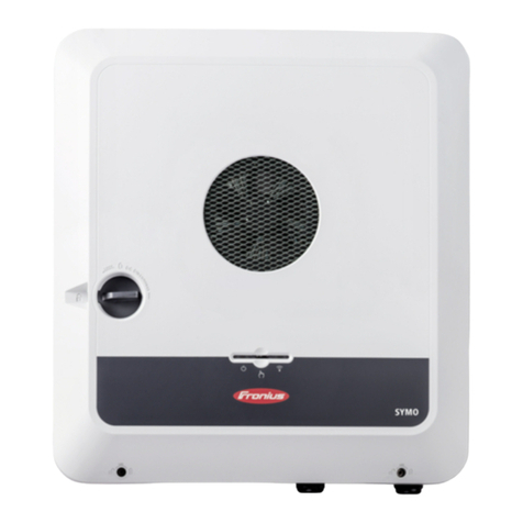
Description of the LEDs on the inverter cover:
POWER led
GREEN On, if the inverter operates correctly. Flashes
in the network control phase or if the sunlight is not
enough.
ALARM led
YELLOW The inverter has detected a fault. For
inverters with a display, the error/warning message
appears on the display.
GFI led
RED Ground fault of the PV array, DC side. For
inverters with a display, the error message appears on
the display.
READ THE MANUAL –ERefer to the product manual for a description
of error/warning codes appearing on the display, for inverters with a
display.
11. Commissioning
ATTENTION –ABefore starting the inverter commissioning
procedure, ensure that all the checks indicated in the previous
sections of this Quick Installation Guide have been correctly
performed and also that the front door 4 have been correctly
closed! Make sure irradiation is stable and adequate for the inverter
commissioning procedure to be completed.
Commissioning could be carried out in two different ways:
• Via “Installer for Solar Inverters” mobile APP - Recommended
mobile APP for commissioning single inverter as well as multi
inverter solar plant.
• Via Web UI (access point wireless network) - Integrated Web User
Interface enabling setting parameters and performing commissioning of a
single inverter (multi inverter support is not provided). Recommended as
alternative method for performing single inverter commissioning.
11.1 Commisioning via “Installer for solar
inverters” mobile app
“Installer for Solar Inverters” is the advanced FIMER mobile APP allows to
simplify commissioning, parameter settings and troubleshooting of FIMER
string multi-inverters in large scale solar plants.
Even in case of single inverter installation it can be consider the most
suitable professional tool to be used. “Installer for Solar Inverters” mobile
APP is available for mobile devices with an Android version of 6.0.1
or greather (iOS mobile devices support will come soon) and could be
downloaded and installed from Play Store.
Commissioning procedure:
• It’s highly recommended to connect the inverters in ethernet daisy chain
(with or without ring) before executing the commissioning procedure.
Make sure that all the inverter being commissioned features the last
firmware version (updating can be executed via Installer for Solar
Inverters mobile APP).
• Supply the input voltage from the photovoltaic generator to the inverter.
ATTENTION –AMake sure irradiation is stable and adequate for the
inverter commissioning procedure to be completed.
The main steps to complete the commissioning procedures are listed below:
• Installer for Solar Inverters mobile APP installed on mobile device.
• Enabled Aurora Vision installer account allowed to use the mobile APP.
The account can be created in the mobile APP directly following the
dedicated wizard procedure.
• Manual claiming of the inverters to be commissioned.
The claiming process consists of indicating which inverters are to
be commissioned.
Claiming process can be executed by scanning the QR codes of all
the inverters being worked and putting the selected inverters into the
working list. Please insert in the list inverters belonging to the same
inverters family; no more than 40 inverters by time can be configured
together. As an alternative of QR code scanning, claiming process
can be executed by selecting manually the SSIDs associated to the
Wi-Fi networks generated by each inverter to commission and inserting
Product key when requested. Both QR code and Product key are provided
on the Communication identification label stuck onto each inverter. The
Communication Identification label is divided in two separate parts by a
dashed line; take the bottom part and apply it on the plant documentation.
(it’s recommend to create a plant map and apply the Communication
Identification label of each inverters in the right position of that map).
NOTE –DAbove steps are valid for executing any available
funtionalities of the Installer for Solar Inverters mobile APP.
• In order to launch the installation wizard and so complete the
commissioning procedure please click “Commissioning” button.
If needed click prevently on “Firmware update” button for aligning
the firmware of all the inverters in the list to the last version
(internet connection is needed).
READ THE MANUAL –EFor more details about commissioning and
any other functionalities of the Installer for Solar Inverters mobile
APP please contact FIMER customer support. For any other specific
settings of parameters of single inverters please refer to “Description
of the Web User Interface” chapter.
11.2 Commisioning via web UI (Access point
wireless network)
The inverter can be commissioned and configured from a wireless device,
such as a Smartphone, a tablet or a laptop. The commissioning procedure
is as follows:
• Supply the input voltage from the photovoltaic generator to the inverter.
• Enable the wireless functionality on the device you are using
for the commissioning of the inverter the network named
FIMER-XX-XX-XX-XX-XX-XX, where “X” is an hexadecimal number
of the MAC Address (the MAC Address is indicated on the “wireless
identification label” on the side of the inverter).
• When prompted, type the “product key” (including the dashes. Example:
1234-1234-1234-1234) as the network password.
• Open your Internet browser (recommended browsers: Chrome from v.55,
Firefox from v.50, Safari from V.10.2.1) and enter the default IP Address
to access the Configuration Wizard page: 192.168.117.1.
This will start the Configuration Wizard:
- STEP 1 - Set the Admin/User access credentials (at least 8 characters
for the password). Username and password are CASE SENSITIVE.
- STEP 2 (optional) - Enter the required information (IP Address selection
mode, SSID, and password) to connect the inverter to the wire less network.
A new message will be displayed showing the IP Address assigned by router
to access to the internal Web server. TAKE NOTE OF THE LINKS.
- STEP 3 - Set the Date, Time and Time Zone.
- STEP 4 - Set the inverter grid standard and configure the input channels.
By clicking “FINISH” the wizard completes the configuration procedure
(after the settings are confirmed, the inverter restarts).
ATTENTION –AFrom the moment the grid standard is selected,
there will be 24 hours available to make any changes to the grid
standard; after this, the “Country Select” feature is blocked and you
can make further changes only by resetting the remaining-time timer.
• Supply the grid voltage to the inverter. Once the AC and DC disconnect
switches are closed and the Configuration Wizard has completed the
configuration procedure, the inverter starts the grid connection sequence.
If the outcome of the preliminary checks is positive, the inverter will
connect to the grid and start exporting power. The “Power” LED remains
solid on, while the “Alarm” and “GFI” LEDs are off.
READ THE MANUAL –EFor more information about the configuration
and use of the internal Web server, refer to the product manual.
12. Arc fault detection
For PVS-60-TL-US-S and PVS-60-TL-US-SC models only, the AFD
performs a self-test when the system is started.
If the self-test results are OK, the inverter will continue to AC grid
connection.
If a potential problem on the AFD board is detected, the self test will
result in error E053.
Refer to the product manual (downloadable as described on the cover
page) for troubleshooting suggestions.
During normal operation the input current is continually measured and
analyzed.
If a DC arc fault is detected during operation, the inverter is disconnects
from AC grid and generates an E050 error code (readable through
internal Webserver).
Press and hold the AFD reset button on the left side of the DC wiring
box for 3 seconds. This will clear the E050 error and restart the self
test.


