3
Installations above 2000 metres
On account of the rarefaction of the air (at high altitudes), particular
conditions may occur:
• Less efficient cooling and therefore a greater likelihood of the device
going into derating because of high internal temperatures
• Reduction in the dielectric resistance of the air that, in the presence of
high operating voltages (DC input), can create electric arcs (discharges)
that can reach the point of damaging the inverter
NOTE –DAll installations at altitudes of over 2000 metres must be
assessed case by case with the FIMER Service department.
Installation position
• Install on a wall or strong structure suitable for bearing the weight
• Install in safe, easy to reach places
• If possible, install at eye-level so that the display and status LEDs can
be seen easily
• Install at a height that considers the heaviness of the equipment
• Install vertically with a maximum inclination of +/- 5°
• To carry out maintenance of the hardware and software of the equipment,
remove the covers on the front. Check that there are the correct safety
distances for the installation that will allow the normal control and
maintenance operations to be carried out
• Comply with the indicated minimum distances
• For a multiple installation, position the inverters side by side
• If the space available does not allow this arrangement, position the
inverters in a staggered arrangement as shown in the figure so that heat
dissipation is not affected by other inverters
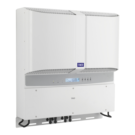
TRIO
POWERALARM GFI ESCUP DOWN ENTER
TRIO
POWERALARM GFI ESCUP DOWN ENTER
TRIO
POWERALARM GFI ESCUP DOWN ENTER
TRIO
POWERALARM GFI ESCUP DOWN ENTER
TRIO
POWERALARM GFI ESCUP DOWN ENTER
TRIO
POWERALARM GFI ESCUP DOWN ENTER
TRIO
POWERALARM GFI ESCUP DOWN ENTER
TRIO
POWERALARM GFI ESCUP DOWN ENTER
TRIO
POWERALARM GFI ESCUP DOWN ENTER
TRIO
POWERALARM GFI ESCUP DOWN ENTER
TRIO
POWERALARM GFI ESCUP DOWN ENTER
50
cm
50
cm
15cm 15cm
TRIO
POWER ALARM GFI ESC UP DOWN ENTER
TRIO
POWERALARM GFI ESC UP DOWN ENTER
TRIO
POWERALARM GFI ESC UP DOWN ENTER
TRIO
POWERALARM GFI ESC UP DOWN ENTER
TRIO
POWERALARM GFI ESCUP DOWN ENTER
TRIO
POWERALARM GFI ESC UP DOWN ENTER
TRIO
POWERALARM GFI ESC UP DOWN ENTER
TRIO
POWERALARM GFI ESC UP DOWN ENTER
TRIO
POWERALARM GFI ESC UP DOWN ENTER
TRIO
POWERALARM GFI ESC UP DOWN ENTER
TRIO
POWERALARM GFI ESC UP DOWN ENTER
TRIO
POWERALARM GFI ESC UP DOWN ENTER
TRIO
POWERALARM GFI ESC UP DOWN ENTER
50
cm
50
cm
15cm 15cm
TRIO
POWER ALARM GFI ESC UP DOWN ENTER
TRIO
POWERALARM GFI ESC UP DOWN ENTER
ATTENTION –AFinal installation of the inverter must not compromise
access to any disconnection devices that may be located externally.
ATTENTION –APlease refer to the warranty terms and conditions
available on the website and evaluate any possible exclusion due to
improper installation.
4. Instruments
LEDs and BUTTONS, in various combinations, can be used to view the status
or carry out complex actions that are described more fully in the manual.
POWER ALARM GFI ESC UP DOWN ENTER
DC
AC
POWER
LED
GREEN On if the inverter is working correctly. Flashes
when checking the grid or if there is insufficient sunlight.
ALARM
LED
YELLOW The inverter has detected an anomaly. The
anomaly is shown on the display.
GFI LED RED Ground fault on the DC side of the PV generator. The
error is shown on the display.
ESC
It is used to access the main menu, to go back to the
previous menu or to go back to the previous digit to be
edited.
UP It is used to scroll up the menu options or to shift the
numerical scale in ascending order.
DOWN It is used to scroll down the menu options or to shift the
numerical scale in descending order.
ENTER
It can be used to conrm an action, to access the submenu
for the selected option (indicated by the > symbol) or to
switch to the next digit to be edited.
The operating parameters of the equipment are displayed through the
display (01): warnings, alarms, channels, voltages, etc.
Description of symbols and display fields.
DC
AC
b1
b2
b3
b4 b6
b7 b9 b10
b17
b16
b14
b13
b12
b11 b15 b18
b20 b22
b21
b19
b23
b8
b5
Description of symbols and display fields.
b1 RS485 data transmission b13 Daily energy produced
b2 RS485 line present b14 PV voltage > Vstart
b3 Radio line present. b15 DC voltage value
b4 Bluetooth line present (*) b16 DC current value
b5 WiFi line present (*) b17 DC/DC circuit part
b6 Warning b18 DC/AC circuit part
b7 Temperature derating b19 AC voltage value
b8 Instantaneous power b20 AC current value
b9 MPP scan running b21 Connection to the grid
b10 Graphic display b22 Grid status
b11 Power graph b23 Cyclic view on/off
b12 Total energy (*) NOT available
5. Lifting and transport
Transport and handling
Transport of the equipment, especially by road, must be carried out with
by suitable ways and means for protecting the components (in particular,
the electronic components) from violent
shocks, humidity, vibration, etc.
Lifting
Where indicated and/or where there is a
provision, eyebolts or handles, which can
be used as anchorage points, are inserted
and/or can be inserted.
The ropes and means used for lifting must
be suitable for bearing the weight of the
equipment.
Unpacking and checking
The components of the packaging must
be disposed on in accordance with the
regulations in force in the country of
installation.
When you open the package, check that the
equipment is undamaged and make sure all the components are present.
If you find any defects or damage, stop unpacking and consult the carrier,
and also promptly inform the FIMER.
Model Mass weight Lifting points n°#
TRIO-5.8-TL-OUTD(-S)-400 25 kg 4
TRIO-7.5-TL-OUTD(-S)-400 28 kg 4
TRIO-8.5-TL-OUTD(-S)-400 28 kg 4
TRIO
POWER ALARM GFI ESC UP DOWN ENTER


