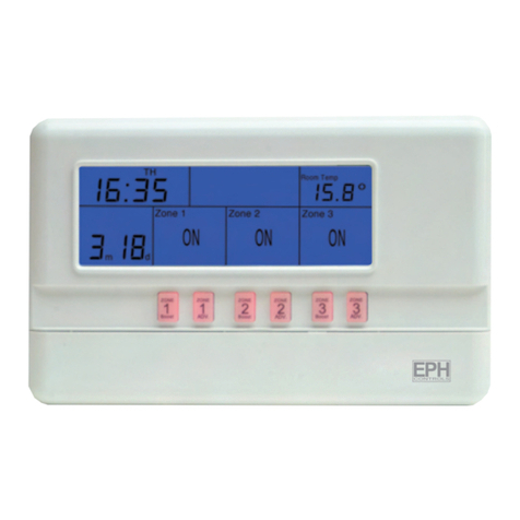
finder 1T.41 User manual

fig. 3
fig. 2
fig. 1
fig. 4
fig. 5
73.3 mm
18 mm
110 mm
N
L
A
B
F
D
E
C
Fig 4/a Fig 4/b
1212
3
Fig 4/c
13
12
3
OK
1T.41
www.findernet.com
IB1T41 - 06/10
I ALIA NO
LEGENDA COMANDI (fig.1)
A: LED ROSSO (Riscaldamento) D: pulsante ESTATE/INVERNO
B: LED VERDE (Raffrescamento) E : selettore GIORNO/NOTTE
C: MANOPOLA GRADUATA ON/OFF F : VANO BATTERIE
CARATTERISTICHE TECNICHE
ALIMENTAZIONE: 2 BATTERIE ALCALINE 1,5 V AAA
CAMPO DI REGOLAZIONE TEMPERATURA RISCALDAMENTO: (+5...+30)°C
CAMPO DI REGOLAZIONE TEMPERATURA RAFFRESCAMENTO: (+8...+30)°C
DIFFERENZIALE TERMICO: 0,3°C
SONDA: NTC
GRADO DI PROTEZIONE: IP20
USCITA: RELÈ
PORTATA CONTATTO: 5 A 250 V AC
MONTAGGIO: A PARETE
INSTALLAZIONE E COLLEGAMENTI
PRESCRIZIONI DI SICUREZZA: prima di collegare il termostato accertarsi che la
tensione di alimentazione del carico utilizzatore da comandare (caldaia, pompe ecc...)
non sia collegata e che corrisponda al valore indicato all’interno del termostato.
POSIZIONAMENTO: installare il termostato lontano da fonti di calore (caloriferi,
raggi solari, cucine) e da porte/finestre, a circa 1,5 mt dal pavimento.
INSTALLAZIONE
- Aprire il termostato premendo il perno sul lato sinistro del dispositivo (fig.2)
- Fissare la parte posteriore alla parete
- Collegare il carico alla morsettiera seguendo lo schema elettrico (cavo Ø 2.5 mm2) (fig.3)
- Chiudere il termostato
SCHEMA DI COLLEGAMENTO (fig.3)
U= carico
C= contatto comune
NO = contatto normalmente aperto
NC = contatto normalmente chiuso
IMPOSTAZIONE ESTATE / INVERNO
Il termostato può essere utilizzato per gestire condizionatori o caldaie a seconda di cosa
è collegato. Premere il pulsante (D) per passare dalla funzione ESTATE a quella INVERNO
o viceversa. Per la funzione ESTATE lampeggerà 3 volte il LED VERDE (B) posto sotto l’icona
VENTOLA; per la funzione INVERNO lampeggerà 3 volte il LED ROSSO (A) posto sotto
l’icona FIAMMA.
IMPOSTAZIONE GIORNO/NOTTE
Spostare il selettore (E) per variare l’impostazione da giorno a notte o viceversa. La
temperatura, nell’impostazione NOTTE, scenderà automaticamente di 3°C rispetto alla
temperatura impostata in quel momento con la manopola graduata (C).
ACCENSIONE/SPEGNIMENTO DEL TERMOSTATO
Ruotare la manopola graduata (C) verso destra per accendere il termostato ed impostare
la temperatura; ruotare la manopola graduata (C) completamente verso sinistra (fino a
sentire uno scatto) per spegnere il termostato.
REGOLAZIONE DELLA TEMPERATURA
Dopo aver selezionato la funzione ESTATE o INVERNO ed impostato il selettore su GIORNO,
ruotare la manopola graduata (C) impostando la temperatura desiderata.
Nota: è possibile, seguendo le istruzioni sotto indicate (fig.4), bloccare meccanicamente
la manopola graduata (C), in modo da poter limitare la temperatura a specifici valori:
- aprire il termostato premendo il perno sul lato sinistro del dispositivo (fig.2)
- con la manopola impostata a 30°C, rimuovere i cavalieri 1- 2 - 3 (fig.4/a)
- ruotare la manopola ed inserire i due cavalieri nei fori riferiti alla temperatura desiderata;
ogni foro corrisponde alla variazione di 1°C; (fig.4/b)
- ruotare nuovamente la manopola in modo che il cavaliere 3 sia inserito/posizionato
tra i cavalieri 1 e 2 (fig.4/c)
- riposizionare la cover e chiudere il termostato
FUNZIONE ANTIGELO
Con il termostato spento (OFF) impostato su INVERNO, la funzione antigelo è attiva (ON).
In caso di accensione della caldaia il LED ROSSO (A) inizierà a lampeggiare.
NOTE DI FUNZIONAMENTO
- Quando il LED ROSSO lampeggia, la caldaia è ON.
- Quando il LED VERDE lampeggia, il condizionatore è ON.
BATTERIA
Alimentazione: 2 BATTERIE ALCALINE 1,5 V AAA.
Quando le batterie non saranno più in grado di fornire alimentazione al
termostato, i due LED lampeggeranno contemporaneamente. Per sostituirle
vedere la fig.5. Sostituite le batterie, il termostato riparte nella condizione
di riscaldamento (il led rosso lampeggia).
Smaltire le batterie esauste in conformità alle norme vigenti.

fig. 3
fig. 2
fig. 1
fig. 4
fig. 5
73.3 mm
18 mm
110 mm
N
L
A
B
F
D
E
C
Fig 4/a Fig 4/b
1212
3
Fig 4/c
13
12
3
OK
1T.41
www.findernet.com
IB1T41 - 06/10
ENGLISH
THERMOSTAT LEGEND (fig.1)
A: RED LED (heater) D: SUMMER/WINTER push-button
B: GREEN LED (air-conditioning) E : DAY/NIGHT selector switch
C: Graduated knob ON/OFF F : Battery Compartment
TECHNICAL DATA
POWER SUPPLY: 2 ALKALINE BATTERIES 1,5 V AAA
TEMPERATURE RANGE HEATING: (+5...+30)°C
TEMPERATURE RANGE COOLING: (+8...+30)°C
TEMPERATURE DIFFERENTIAL: 0,3°C
SENSING ELEMENT: NTC
DEGREE OF PROTECTION: IP20
OUTPUT: RELAY CONTACT
RATING: 5 A 250 V AC
MOUNTING: WALL MOUNTED
INSTALLATION AND CONNECTIONS
SAFETY REQUIREMENTS: before installing this programmable thermostat, make sure
that the supply voltage to the equipment load (heater, pump, etc.) is not connected
and that the load is within the ratings shown inside the thermostat.
POSITIONING: install the programmable thermostat away from sources of heat
(heaters, direct sunlight, kitchens) and from doors/windows, at a height of about
1.5 m above the floor.
INSTALLATION
- Release the small catch with the aid of a screwdriver and remove cover (fig.2)
- Fix the base to the wall
- Connect the load to the terminals following the wiring diagram (cable Ø 2.5 mm2) (fig.3)
- Replace cover and re-set the catch
ELECTRICAL CONNECTIONS (fig.3)
U= equipment load
C= common terminal
NO = normally open terminal
NC = normally closed terminal
SUMMER/WINTER SETTING
The thermostat can be used for “summer” or “winter” operation, depending on whether it
is connected to an air-conditioner or to a heater. Press the button (D) to change from
SUMMER to WINTER setting, or vice versa. Choosing the SUMMER setting, the GREEN
LED (B) blinking 3 times; choosing the WINTER setting, the RED LED (A) blinking 3 times.
DAY/NIGHT SETTING
Move the selector (E) to change from DAY to NIGHT setting and vice versa. Under NIGHT
setting, the temperature is automatically setback by 3°C from the DAY temperature as set
by the graduated knob (C).
THERMOSTAT START-UP/SWITCHING OFF
Turn the graduated knob (C) to the right, to switch-ON the thermostat and to set the
temperature; Turn the graduated knob (C) fully to the left (until to heard a click) to switch
the thermostat OFF.
SETTING THE TEMPERATURES
After having set either SUMMER or WINTER setting, chose DAY by the selector (E) and
turn the graduated knob (C) to the desired temperature.
Note: following the instructions below (fig.4) it is possible to mechanically block the
graduated knob to restrict the set temperature within specific limits.
- Release the small catch with the aid of a screwdriver and remove the cover (fig.2).
- With the knob set to 30°C, remove the tappets 1, 2 and 3 (fig.4/a).
- Rotate the knob to reveal a series of holes, and insert 2 tappets appropriate to the required
upper and lower limits. Each hole corresponds to 1°C (Fig.4/b).
- Turn the graduated knob such that the third tappet can be inserted in the position shown,
ensuring it is between tappets 1 and 2 (fig.4/c).
- Refit the cover and re-set the catch.
FROST PROTECTION OPERATION
With the thermostat turned OFF (under WINTER setting) frost protection is ON.
Should the heater turn on, the RED LED will blink.
OPERATIONAL NOTES
- When the RED LED blinking, the heater is ON.
- When the GREEN LED blinking, the air conditioning is ON.
BATTERY
Power Supply: 2 ALKALINE Batteries 1.5 V AAA. When the batteries are
low, the RED and GREEN LED will blink contemporaneously; for changing
the batteries, see fig.5. After replacing the batteries, the thermostat re-starts
in the heating mode (the RED led blinking).
Please dispose of the worn out batteries according to prevailing regulations.
This manual suits for next models
4
Table of contents
Languages:
Other finder Thermostat manuals
finder
finder BLISS WI-FI CHRONOTHERMOSTAT 1C.91 User manual
finder
finder 1C.51 User manual
finder
finder 1T.31 User manual

finder
finder BLISS2 User manual
finder
finder 1C Series User manual
finder
finder 1C.81 User manual
finder
finder Bliss 2 User manual
finder
finder BLISS T 1T.91 User manual
finder
finder 1T Series User manual
finder
finder 1C.71 User manual


