Finger Crystal E202 User manual
Note: Please prepare a Phillips screw driver and 4 AA batteries before
installation.
1. Keep your fingers clean before using this product.
2. In original settings, it can be unlocked with any fingerprint, any card,
or password `1234567890` and `#`.
3. If the power is insufficient, there will be an alarm prompt, please
replace with 4 new batteries in time.
4. Please don`t use corrodent material to clean the surface.
5. When the password/fingerprint/card/APP can not unlock the door,
please use the key to unlock the door. Please keep the emergency key
with you or put it in outdoor safe place.
6. The lock is suitable for 40-100mm thick doors.
Features
1. The total capacity of system is 300, and Fingerprint capacity is up to 100,
and the first three are administrator.
2. Touching button, durable.
3. Support 6-8 password and 20 virtual password.
4. Support low power warning.
E 2 0 2
S m a r t L o c k U s e r M a n u a l
Please read this manual carefully before use
http://en.fingercrystal.com
Customer Service: (+86)+400 900 5952
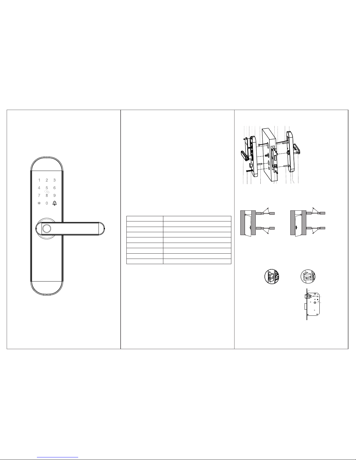
Information & Safety Warnings
Name
Fingerprint Sensor
DPI
Identify Time
Unlock Way
System Capacity
Supply Voltage
Low Voltage Warning
Standby Current
Parameter
semiconductor
500
0.3S
Fingerprint, Card, Password, Key and APP
300
6V
4.8V
<=50uA
Installation
1. Installation Instructions
a. It is recommended to look for professionals to install, watch the video
carefully before installing.
b. Please note that the connection line can’t be pressed or folded during
installation.
c. Before the installation, the lock must be selected correctly according
to the door opening direction, because the handle can't be adjusted.
d. While installing, the door must be in half open state until the
commissioning is completed.
e. After the installation is completed, when the fingerprint, card,
password(1234567890) and #, APP, key unlock, test whether the front
handle and back handle unlock/lock normally or not.
. If it does not work properly, please check if there is improper installation f
or the power cord is loose.
1
23
45
6
8
10 9
191716 18
14
13
1211 20
7
2. Installation Overview
1.Front Panel
2.Connection Column
3.Square Steel
4.Lock Body
5.Connection Line
6.Back Panel
7.`SET` Button
8.Connectiion Column Screws
9.Battery Cover
10.Battery Cover Screw
11.Back Handle
12.Connectiion Column Screws
13.Reverse Lock Knob
14.Back Locking Paddle
15.Latch-bolt
16.Lock Body Screws
17.Connectiion Column
18.Key Hole
19.Emergency Power Port
20.Front Handle
15
Left Hand Door Indoor
Left In
Outdoor
Left Out
Right In
Right Out
Right Hand Door
3 Confirm The Direction of The Door.
T hi s s mart lock is suitable for Le ft O ut /L ef t I n/ Ri gh t O ut /R ig ht In) 4 k in ds o f d oo r
o pe ni ng d ir ec ti on s.
Indoor
Outdoor
Indoor
Outdoor
Indoor
Outdoor
4. Open Hole
Please refer to the opening hole drawing, and drill right holes on the door.
Left Out/
Right In
Left In/
Right Out
5. Install Lock Body
5.1. Choose the installation direction of the latch-bolt of the lock body by
the door opening directions.
5.2. Change the direction of lock body
a. Push the reversing block to the other
side.
b. Push the latch-bolt into the lock and
turn 180 degrees.
c. Put back the reversing block, and the
latch-bolt will pop up automatically.
Reversing block
latch-bolt
Lock Body(5052)
5.3. Put the lock body into the door frame and tighten 2 fixing screws.
Square Steel
Hole

Door
Warranty Card
1. Please fill out the warranty card and keep it well.
2. The warranty period of this product is 18 months.
3. The following belongs to the scope of non warranty:
a. The warranty has expired.
b. Damage occurred during or in relation to non-routine and/or unauthorized
disassembly.
c. Failure to provide a valid proof of purchase when requesting service or repair.
d. Damage occurred as a result of natural disaster.(including earthquake, fire,
flood etc.)
e. Damage occurred due to unexpected factors or man-made reasons.
(including mis-operation, improper insert or pulling, hauling, bumping,
improper voltage input and others)
4. We will charge for the repairing if it is out of warranty.
5. When the product breaks down, ask your local dealer for repair and write
out specific information below.
Product Name
Product Price
User Name
User Address
Seller Name
Seller Address
Order Number
7.2. Install the front panel.
a. Insert the suitable square steel into the
lock body.
b. Pass the connection line through the door
hole.
c. Align the square steel with the square steel
hole of the front panel and fix the front panel
on the door, then press the other end of the
square steel.
7.3. Install the back panel.
a. Press the front panel, and connect the
connection line with the corresponding
interface of the back panel, then Insert
the excess line into the door hole.
b. Insert back locking p into the lock addle
body, and you can cut off one or two
sections of back locking paddle according
to the thickness of the door.
c. Align the square steel with the square
steel hole of the back panel, and compress
the back panel.
d. Lock 2 connection column screws to fix the back panel.
e. Install 4 AA batteries and the battery cover, then lock the battery
cover screw.
Add The Administrator
1. Remove the battery cover, short press `Set`(back panel) or long press `*`, then
the voice prompts: `Please add administrator`.
2. Add admin`s fingerprint(the same fingerprint,3 times), card, or
password (6-8 numbers) and `#`(the same password, 2 times).
3. The voice prompts: `add successfully`.
4. Then you can continue to add.
Notes: 1. The first three are administrator.
2. `*`: Back, Sign out button, `#`: confirm button.
Add The User
1. Remove the battery cover, short press `Set`(back panel) or long press `*`, then
the voice prompts: `Please verify the administrator`.
2. Verify the administrator.
3. Add user`s fingerprint(the same fingerprint,3 times), card, or
password (6-8 numbers) and `#`(the same password, 2 times).
4. The voice prompts: `Add successfully`.
5. Then you can continue to add.
Delete The User
1. Remove the battery cover, short press `Set`(back panel) or long press `*`, then
the voice prompts: `Please verify the administrator`.
2. Verify the administrator.
3. Short press Set(back panel) or long press `*` again.
4. Press `1` to remove all user fingerprints, press `2` to remove all user passwords,
press `3` to remove all user cards, press `4` to remove all users.
5. The voice prompts:`successful`.
Note: The administrator can`t be removed by doing this.
Reset The Lock
1. Remove the battery cover, long press `Set` for 3 seconds.
2. The system restore to the factory default settings.
Notes:
1. After the reset, all the information are removed (including administrator).
2. Administrator password will return to its default `1234567890`.
3. Please add a new administrator immediately.
APP Installation
1. Search `tuyaaoni` in APP store, download and install APP.
2. Registration and login with the mobile phone number.
3. Please refer to the operation prompt to complete the network configuration.
Add Network
1. Short press `3`+`#`, Verify the administrator.
2. Network configuration mode: press # to change.
a. Normal mode: the LED of `8` fast flash, please add network in APP.
b. Compatibility mode: the LED of `8` slow flash, please add network in the
Compatibility mode of APP.
3. Add successfully: The voice prompts `add successfully`.
4. Add failure: LED light show `X` and the voice prompts `add failure`.
Self-locking
If the password is entered wrong for 5 times continuously, the system will be locked
for 180 seconds, and the fingerprint or card unlock can remove self-locking.
Low Power Warning
When the battery power is lower than 4.8V, the lock will prompt `The battery is use
up, please replace it`, please replace with 4 new batteries in time.
Virtual Password
Enter virtual password before or after the real password, it can be unlocked.
Using The Lock
4.72 Inch 1.77 or 2.17 Inch 2.76 and 3.54 Inch3.55-3.94 Inch
5.51 Inch 1.77 or 2.17 Inch 3.54 and 4.33 Inch
>3.94 Inch
6. Choose The Parts
Choose suitable parts according to the following table.
Door thickness
Square Steel
Connection Column
3.15 Inch 1.38 Inch
1.18 and 1.97 Inch
3.15 Inch
3.94 Inch
Connection Column
1.77 or 2.17 Inch 1.18 and 1.97 I n c h
1.77 or 2.17 Inch
1.57-2.16 Inch
2.17-2.36 Inch
2.76-3.15 Inch 1.97 and 2.76 Inch
Length Length Screw Length
7.1. Install 2 connection columns
on the front panel.
7. Install The Lock
8. Install Buckle Plate And Buckle Box
Tapping Screw
Buckle Plate
Buckle Box
Door Frame
Back Locking Paddle
a
b
c
d
d
Connection Column
Door
Screws Hole
Square
Steel
Hole
FCC STATEMENT :
This device complies with Part 15 of the FCC Rules. Operation is subject to the following
two conditions:
(1) This device may not cause harmful interference, and
(2) This device must accept any interference received, including interference that may
cause undesired operation.
Warning: Changes or modifications not expressly approved by the party responsible for
compliance could void the user's authority to operate the equipment.
Note: This equipment has been tested and found to comply with the limits for a Class B
digital device, pursuant to Part 15 of the FCC Rules. These limits are designed to provide
reasonable protection against harmful interference in a residential installation. This
equipment generates uses and can radiate radio frequency energy and, if not installed
and used in accordance with the instructions, may cause harmful interference to radio
communications. However, there is no guarantee that interference will not occur in a
particular installation. If this equipment does cause harmful interference to radio or
television reception, which can be determined by turning the equipment off and on, the
user is encouraged to try to correct the interference by one or more of the following
measures:
Reorient or relocate the receiving antenna.
Increase the separation between the equipment and receiver.
Connect the equipment into an outlet on a circuit different from that to which the
receiver is connected.
Consult the dealer or an experienced radio/TV technician for help.
FCC Radiation Exposure Statement:
This equipment complies with FCC radiation exposure limits set forth for an uncontrolled
environment. This equipment should be installed and operated with minimum distance
20cm between the radiator & your body.
Product Model
Date of Purchase
User Phone
Seller Phone
Maintenance records(Filled in by the maintenance agency)
Date Fault Result Signature
Popular Lock manuals by other brands


Sealey
Sealey FPS7 instructions

Yale
Yale Assure Lock YRD216 Installation and programming instructions

Gantner
Gantner GAT ECO.Side Lock 7000 BA Installation, commissioning & operation

GTO
GTO RB909 installation manual

Conrad
Conrad TSA Zipper Lock manual

Chamberlain
Chamberlain MG 1300 Wiring & specifications

FingerTec
FingerTec H2i user guide

Gianni Industries
Gianni Industries ML-400M Installation instruction

SECO-LARM
SECO-LARM SLI E-941SA-600 manual

Lockwood
Lockwood 3578 Series Mounting instructions

Turbolock
Turbolock TurboSafe user manual

National Cabinet Lock
National Cabinet Lock C8109 Dimensional drawing