manuals.online logo
Brands
  1. Home
  2. •
  3. Brands
  4. •
  5. Lockwood
  6. •
  7. Lock
  8. •
  9. Lockwood 3578 Series User manual

Lockwood 3578 Series User manual

3578 SERIES MORTICE LOCK with HOLD BACK
MOUNTING INSTRUCTIONS
P/No. 3578-5121 30621 0506
RIGHT - HAND DOOR LEFT - HAND DOOR
OUTSIDE
DOOR OPENING
IN
OUTSIDE
DOOR OPENING
OUT
OUTSIDE
DOOR OPENING
OUT
OUTSIDE
DOOR OPENING
IN
1
2
SETTING LOCK STATUS
SETTING LOCK STATUS
HAND OF DOOR ACCORDING TO ENGLISH PRACTICE
Determine hand of lock required from hand of door chart above.
All Lockwood 3578 Series Mortice Locks are mounted in accordance
with these instructions. Locks may or may not have cylinders,
lever handles, turn knob or emergency button. Disregard instructions
referring to the features not required.
Important : Before drilling door, ensure correct hand is being installed.
NOTE: CASE DOES NOT need to be opened, to change HAND or
FUNCTION of LOCK.
HANDING OF LOCK
Determine hand of lock required from above hand of door chart.
Rotate bolt head to suit latching direction. Ensure lock is in UNLOCKED position.
To UNLOCK (if required), using a small screwdriver, lever out Cylinder Hole
Plug where fitted and lift snib using the screwdriver.
SNIB CAM
Rotation of the Snib Cam hands the lock. Use a small screwdriver to rotate
cam if required.
Combination locks
(Both handles can be locked) DOT in the up position.
Vestibule Locks
With single action escape feature. DOT to be DOWN on ESCAPE
side and UP on LOCKABLE side.
LOCK UP WITH LOCKWOOD
COMBINATION
LOCKABLE LOCKABLE
VESTIBULE
RIGHT HAND
DOOR
LOCKABLE ESCAPE
VESTIBULE
LEFT HAND
DOOR
ESCAPE LOCKABLE
4
Establish height that lockset will be mounted on door and mark centreline of
door thickness on door edge.
Place Mortice Template on door and align centreline on template with
centreline on door. Secure with sticky tape.
Mark and drill mortice to suit mortice lock depth (90mm).
THIS IS A COMMON TEMPLATE FOR
3560 SERIES MORTICE LOCKS.
BEFORE DRILLING HOLES, CHECK
THAT THEY WILL SUIT LOCKSET
TO BE FITTED.
ENSURE LOCK IS REMOVED FROM MORTICE
HOLE
22mm DIA
FOR SPINDLE
EDGE A
2 HOLES
20mm DIA
FOR CYLINDER
60 mm Backset
Centreline
Mortice template
Door
FOLD LINE ALONG EDGE OF DOOR 60mm BACKSET
Mortice
Centreline
IMPORTANT - To prevent damage to the door face from
drill "breakthrough", MARK BOTH SIDES OF DOOR &
DRILL HOLES HALF WAY THROUGH EACH SIDE
UNLOCKED
LOCKED
3
Establish which side the adaptor is to be located, lever out Cylinder hole plug
where fitted.
PUT LOCK IN LOCKED POSITION, as shown in Step 1.
Insert Adaptor into lock body with TOP of Turn Knob Cam point away from front
of lock body. Ensure Turn Knob Cam is engaged in yoke of snib as shown.
Place retainer pin through front plate to retain adaptor to lock. Ensure pin is
flush with front plate
YOKE
TURN KNOB CAM
TURN KNOB ADAPTORS DOOR PREPARATION
Strike
Strike
Box
Jamb
P
L
E
A
S
E
R
E
C
Y
C
L
E
T
H
I
S
P
A
C
K
A
G
I
N
G
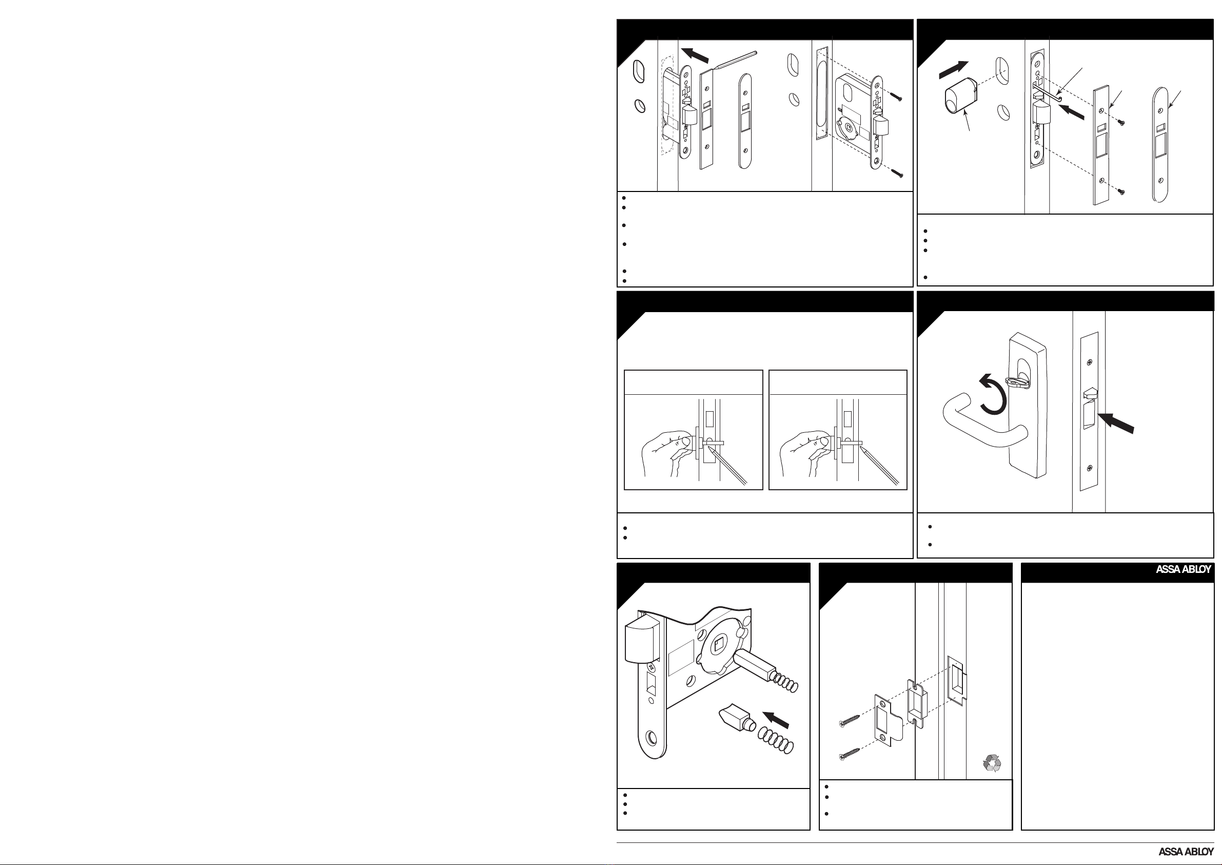
Mark out door frame for strike.
Mortice door frame for strike box and strike. Bolt
recess to be 15mm deep in door frame.
Screw strike and strike box to the door frame with
two screws supplied with mortice lock.
All locks are supplied with spindles.
Insert spindle(s) into lock, as required.
Assemble furniture as required. Ensure furniture is
not over-tightened.
9 LOCKS WITH SPINDLES 10 MOUNTING STRIKE LOCKWOOD GUARANTEE
7
Mark and cut connecting bar as shown.
Turn knob to be in the vertical position when UNLOCKED.
LOCKS WITH TURNKNOBS
LATCHING OR
LOCKING TURNKNOB
EMERGENCY TURNKNOB
FUNCTION
IMPORTANT :
Attach spindle spring to rear
of spindle before assembling
ASSA ABLOY Australia Pty Limited, (“ASSA ABLOY”), guarantees its
products against defects in
workmanship
and materials. If within the
normal working life of a product it is found to be defective, ASSA
ABLOY
will supply the same or an equivalent product free of charge.
All electrical and electronic components used in Lockwood’s range
of products excluding batteries are guaranteed for a period of
12 months from the date of proof of purchase, unless otherwise stated.
ASSA ABLOY assumes no liability under this guarantee for the
following :
1. Improper installation or failure to follow fitting instructions.
2. Failure due to improper maintenance.
3. Failure due to fair wear and tear.
4. Indirect or consequential loss or damage.
5. Cost of removal and/or replacement.
6. Cost of freight and/or replacement.
7. The plated finishes Florentine Bronze, Architectural Bronze,
Polished Brass and Satin Brass are classified as soft finishes.
As deterioration is possible under some climatic conditions,
these finishes are excluded from this guarantee.
8. Any modification to a product as supplied, or repaired, unless
authorised by ASSA ABLOY.
9. Use of replacement part other than authorised parts.
10. Malfunction or failure of the product due to use of
non-genuine Lockwood parts.
11. Malfunction or failure of the product due to the use of
non-specified batteries.
Nothing in the Lockwood Guarantee excludes, restricts or modifies
any condition, warranty, right or liability implied or protected by law
where to do so would render the Guarantee, or any part of it, void.
ASSA ABLOY Australia Pty Limited, 50 Edward Street, Oakleigh VIC 3166, ABN 90 086 451 907 © 2006
An ASSA ABLOY Group brand
5 DOOR PREPARATION
Ease out mortice cavity where necessary. Clean out mortice before inserting lock.
Insert lock in mortice with Cover Plate on and scribe around Cover Plate for size of
recess, ensuring that no foreign matter finds it way into the lock mechanism.
Remove lock from mortice and chisel recess 4mm deep to receive both front
and cover plate. Cover plate must be flush with edge of door.
Ensure lock is removed from mortice cavity. Fold template along backset fold
line. Align EDGE A with bottom of cover plate recess. Establish holes required to
suit lock function, mark hole centres accurately, drill and clean holes.
Drill furniture holes as required.
Fasten mortice lock into door using mounting screws provided.
6
LOCKS WITH CYLINDERS
Place lock in mortice and insert cylinder.
Secure cylinder with retainer pin, ensuring pin is flush with front plate.
Install Cover plate and secure with 2 M4 screws provided to lock body.
LOCKS WITHOUT CYLINDERS
Install Cover plate and secure with 2 M4 screws provided to lock body.
LOCKS AND CYLINDERS
To activate HOLD BACK function, depress latchbolt with thumb and turn key
or turn knob.
To de-activate HOLD BACK function turn key or turn knob in opposite direction.
8 ACTIVATING HOLD BACK FUNCTION
Cover plate
(Square)
Cover plate
(Round)
Cover
plate
(Square)
Cover
plate
(Round)
Cylinder
retainer
pin
Cylinder
assembly

Other Lockwood Lock manuals

Lockwood PADDE TRIMEC 200 Series User manual

Lockwood

Lockwood PADDE TRIMEC 200 Series User manual

Lockwood Nexion Classic User manual

Lockwood

Lockwood Nexion Classic User manual

Lockwood ST8011SSS User manual

Lockwood

Lockwood ST8011SSS User manual

Lockwood ASSA ABLOY Induro User manual

Lockwood

Lockwood ASSA ABLOY Induro User manual

Lockwood ES150 Series User manual

Lockwood

Lockwood ES150 Series User manual

Lockwood PADDE TRIMEC PRE-LOAD ES9000 Series User manual

Lockwood

Lockwood PADDE TRIMEC PRE-LOAD ES9000 Series User manual

Lockwood Digital Deadbolt User manual

Lockwood

Lockwood Digital Deadbolt User manual

Popular Lock manuals by other brands

COMPX C8142 Dimensional drawing

COMPX

COMPX C8142 Dimensional drawing

position ECS5000 installation manual

position

position ECS5000 installation manual

CDVI SOLARKPW installation manual

CDVI

CDVI SOLARKPW installation manual

Fapim GAIA quick start guide

Fapim

Fapim GAIA quick start guide

Simons Voss Technologies ALLEGION 3061 manual

Simons Voss Technologies

Simons Voss Technologies ALLEGION 3061 manual

Häfele LockerLock LL 200 installation instructions

Häfele

Häfele LockerLock LL 200 installation instructions

FSH FEM3500 manual

FSH

FSH FEM3500 manual

Kaadas S110B-F manual

Kaadas

Kaadas S110B-F manual

Rousseau L13-OC20S Assembly guide

Rousseau

Rousseau L13-OC20S Assembly guide

Siegenia KFV GENIUS 2.1 PANIC Assembly instructions

Siegenia

Siegenia KFV GENIUS 2.1 PANIC Assembly instructions

Yale Smart Latch 2 manual

Yale

Yale Smart Latch 2 manual

VITRA Dial Lock operating instructions

VITRA

VITRA Dial Lock operating instructions

schmersal AZ 201-B40 operating instructions

schmersal

schmersal AZ 201-B40 operating instructions

Schlage CM993 Series Installation instructions and information manual

Schlage

Schlage CM993 Series Installation instructions and information manual

Ingersoll-Rand Schlage Camelot FE365-CAM-GEO Programming guide

Ingersoll-Rand

Ingersoll-Rand Schlage Camelot FE365-CAM-GEO Programming guide

COMPX MFWSG29000 Dimensional drawing

COMPX

COMPX MFWSG29000 Dimensional drawing

Assa Abloy IKON VERSO CLIQ V551 operating instructions

Assa Abloy

Assa Abloy IKON VERSO CLIQ V551 operating instructions

COMPX CB-250 instruction sheet

COMPX

COMPX CB-250 instruction sheet

manuals.online logo
manuals.online logoBrands
  • About & Mission
  • Contact us
  • Privacy Policy
  • Terms and Conditions

Copyright 2025 Manuals.Online. All Rights Reserved.