Finsterwalder Paralock 3 User manual

Operating limitations
Breaking load: 2,800 DaN (1 DaN corresponds to approx.1 kg)
Working load limit: 120 DaN
Replacement interval from commissioning: 8 years mono, 5 years tandem
When using the Paralock on a paraglider with a speed system,it is strongly recommended to install a system that automatically disconnects
the speed system when the Paralock is released. Suitable separation systems are available from the FINSTERWALDER & CHARLY webshop.
Instruction Manual
Paralock 3
Paragliding Carabiner
HKar130
Version 09/2023
Latest version available at:
www.nsterwalder-charly.de
Knob bolt
Locking joint axle
Release knob
Harness strap chamber
Ramp for
knob bolt
Securing pin
Release lever
Spring cover
Lever bearing
Lock

1. The lock of the Paralock must be closed. Only then can the release lever be unblocked by moving
the securing pin.
2. Unlock the release lever: Grasp the release button with three ngers and turn it counter-clockwise
a quarter of a turn until it stops. This will pull the knob bolt out of the hole. The release lever is
now free and you can swivel it upwards against friction and spring force in an anti-clockwise
direction.
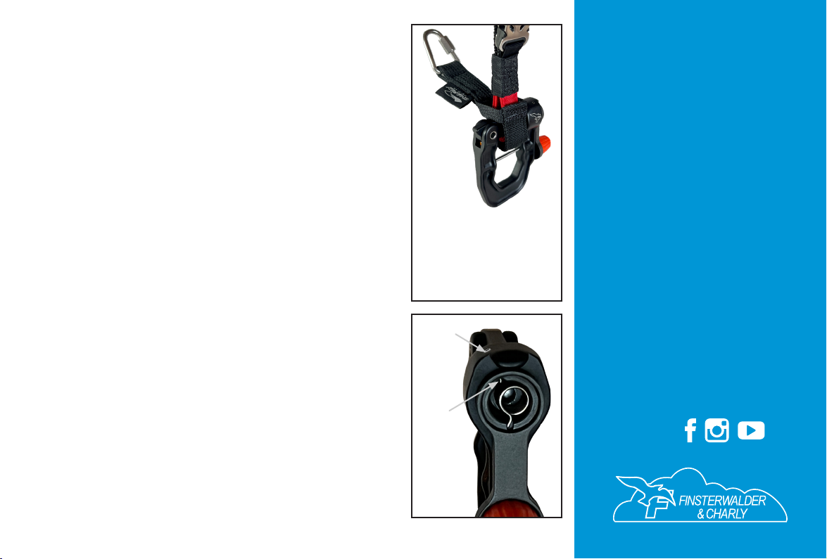
3. Hold the lever in a swung out position of approximately 30°. In this position, you can push the
securing pin completely out of the Paralock (Fig. 1).
4. Once the securing pin has been removed, unlock the lock of the Paralock by turning the release
lever upwards as far as it will go. You can now open the unloaded lock fully by hand against the
spring force. In this position it remains open and you can attach the harness or risers. When the
Paralock is under load, pulling on the risers will open the lock at approximately 80° of deection
of the release lever. It may be necessary to make a shaking movement to release the risers when
the lock is open.
5. To reinsert the securing pin, close the lock and swing the release lever upwards until the hole for
the securing pin is free. When reinserting the securing pin, ensure that the side of the pin with
the two grooves is inserted rst.
Suitable harnesses
The Paralock is suitable for all straps, as long as they t into the harness strap chamber below
the securing pin. 45 mm wide straps are folded over to reduce their width. The loops of the main
suspension of the harness must be at least 28 mm long to allow the Paralock to pass through. The
harness is hooked in with the release lever pointing towards the pilot, i.e. to the right for right-
handed pilots and to the left for left-handed pilots (Fig. 2). Some harnesses (e.g. Advance’s Impress)
have a separate suspension for the cocoon. This can be attached above the securing pin as long as it
does not apply a lateral load of more than 100 DaN to the Paralock.If the paraglider is equipped with
a speed system, an appropriate separation link should be installed.
Operation and release test after installation on the pilot’s harness
The function test must be carried out hanging near the ground. Check that the release lever can
rotate freely. The separation link’s release line must not be under tension when the speed system
is at full travel.
Caution: The Paralock is not designed to be released frequently under full load as this may cause
excessive wear on the knob bolt. Such wear will not occur if the Paralock is activated after an
emergency deployment or after landing, as the Paralock is then largely unloaded. Replacing a worn
knob bolt is straightforward and is described later in this manual.
Intended use
The Paralock is a universal air sports carabiner for mono and tandem use, which allows a quick
separation between the pilot’s harness and the glider,even under load. This separation can be useful
and life-saving in many situations:
• Disconnecting the paraglider after deploying the reserve prevents unwanted interaction between
the paraglider and the reserve. This avoids a dangerous downplane conguration or pendulum
and shearing movements between the paraglider and the reserve.
• A paraglider separated on one side or completely allows you to take advantage of the lift-
generating lateral drift of modern reserve parachutes. The drift signicantly reduces the rate of
descent, increases the deceleration distance in an inclined impact and reduces the forces on the
spine.
• The ability to select a landing site with a steerable reserve is an important safety feature. If the
paraglider is not disconnected, this option is not used.
• A rescue option is available in the event of a landing in surf and owing water.
• The paraglider/reserve can be disconnected after landing in strong winds or when hanging in
trees.
• A paraglider that has been disconnected will collapse very quickly and is easy to recover.
Caution: It is strongly recommended that the Paralock should not be operated during the approach
unless a water landing is unavoidable. The Paralock should also remain closed during ight unless
the reserve is fully deployed.
Functionality of the securing pin
When the Paralock is closed, the securing pin can be moved along the axis by gripping it rmly with
two ngers and it will lock in two positions. Moving the securing pin towards the release knob
will block the release lever. When the Paralock is open, the securing pin cannot be moved. This
prevents the securing pin from being operated before the release lever snaps shut and locks into
place.
Caution: The blockage of the securing pin when the Paralock is open can be overcome and
damaged by the use of force. Therefore, do not attach anything to the securing pin to make it easier
to operate.
Installation on the harness
To install the Paralock on the harness, the securing pin can be removed without tools. Proceed as
follows:
Instruction manual | FINSTERWALDER Paralock 3 Paragliding Carabiner | Version 09/2023
Fig. 2
Instruction manual | FINSTERWALDER Paralock 3 Paragliding Carabiner | Version 09/2023
Fig. 3
Attaching the risers
The Paralock is suitable for paraglider risers with a width of up to 26 mm. To attach the risers, open
the lock completely. Then place it on the lever bearing and bring it into the locking position (Fig. 3).
To close and lock the Paralock, turn the release lever to the upper stop and release it so that it snaps
shut and locks into place.The knob bolt will slide over the ramp and automatically secure the lever.
Caution: The correct sliding and engagement of the knob bolt must be routinely checked by
pressing against the release lever!
Modes of operation
Depending on personal preference, the Paralock can be used in two different operating modes:
Operation with unblocked release lever
Unlike conventional carabiners, it is not possible to launch with a riser caught in the lock. The
Paralock’s lock is either securely closed or fully open. When it is open, the pilot remains on the
ground. When you release the lever from the open position, the Paralock locks automatically, and
after checking that the knob bolt is securely engaged by applying counter-pressure, the Paralock
is secured and ready for ight. It is not possible to unlock it by simply pushing against the release
button.Additional securing of the release lever is thus not required.The securing pin remains in the
open position on the side opposite the release lever. The connection can then be released at any
time without delay, even when wearing gloves. This mode of operation is recommended for safety
training, in developing emergency situations or for ground handling of the paraglider in strong
winds.
Operation with blocked release lever
Most paraglider pilots rarely nd themselves in a situation where they need to deploy their reserve
or disconnect from the glider under load.For them,the advantage of the Paralock,apart from its ease
of use and long replacement interval, is that they do not need to carry an emergency knife. If you
are uncomfortable with the Paralock’s quick-release feature, you should use the blocking option of
the release lever. In tandem use, however, the blocking of the release lever is mandatory in
any case. It is part of the Paralock’s security concept that the securing pin can only be operated by
gripping it with two ngers. With a little practice, blocking and unblocking can usually be done in
seconds, even when wearing gloves. Unintentional operation of the securing pin while the release
lever is snapping shut is impossible with this mode of operation, as this would require the use of a
second hand.
Caution: Blocking the release lever is no substitute for routinely checking that the knob bolt
slides and engages properly!
Fig. 1
Finsterwalder GmbH
Charly Produkte
Pagodenburgstr. 8
81247 Munich
GERMANY
Phone +49 89 8116528
E-mail ofce@nsterwalder-charly.de
Website www.nsterwalder-charly.de
Webshop shop.nsterwalder-charly.de
nd us on
Care and maintenance
The hard anodised bearing of the release lever is virtually maintenance free. In case of soiling,
acid-free oils or greases, e.g. WÜRTH HSS Lube, can be used as a lubricant. When the lever is
deected 30-45°, it should reliably return to the locked position when released.
Replacing the knob bolt
1. Remove the Phillips screw from the release button.
2. Carefully unlock the release lever and turn it out.
3. Hold the knob and eject it by turning the release button.
Caution: Carefully tighten the Phillips screw during assembly to avoid damaging the thread in
the plastic.
Dismounting the lock
Push out the locking joint axle, taking care not to lose the ball inside the joint.
Removing and reinstalling the release lever to clean the release lever bearing
1. Unscrew the spring cover on the release lever bearing wit a 3 mm hex wrench.
2. Remove the leg spring.
3. Push the 2 mm hollow splint into the spring chamber.The release lever can now be removed.
4. To secure the lever, insert the hollow splint from the outside and allow it to protrude 1 mm.
5. Insert the lower arm of the leg spring into the hole of the hollow splint and tighten and hook
in the upper arm as shown in Fig. 5. Provided that the lower arm of the leg spring is correctly
seated in the hole of the hollow splint (and not next to it), the release lever should now be
under tension when it is turned. Finally, press the hollow splint in until it is ush.
Fig. 4
Towing with the Paralock
Towing requires the use of a
towing adapter or a towing
release with integrated towing
adapter.
Version 09/2023
Latest version available at:
www.nsterwalder-charly.de
Fig. 5Splint
The lower
arm of
the leg
spring
must
rest in
the split.
Popular Safety Equipment manuals by other brands

Lanex
Lanex PB-20 instruction manual

SKYLOTEC
SKYLOTEC ANCHOR ROPES Instructions for use

Besto
Besto Buoyancy Aid 50N Instructions for use

TEUFELBERGER
TEUFELBERGER NODUS Manufacturer's information and instructions for use

Troy Lee Designs
Troy Lee Designs Tbone Product owners manual

Innova
Innova Xtirpa Instruction and safety manual

bolle SAFETY
bolle SAFETY B810 quick start guide

SHENZHEN FANHAI SANJIANG ELECTRONICS
SHENZHEN FANHAI SANJIANG ELECTRONICS A9060T instruction manual

Hiltron security
Hiltron security POWER8E Installation and use manual

Salewa
Salewa MTN SPIKE user manual

Hatco
Hatco B-950P installation guide

Sitec
Sitec TX MATIC operating manual


