BG-12LXSP Addressable Pull Station
Patented, U.S. Patent No. Des. 428,351; 6,380,846; Other Patents Pending
Document 52148 I56-3663-001
Description
The BG-12LXSP Addressable pull station is a non-coded, dual-action manual pull station
with a key-lock reset feature. It also has dual language (Spanish/English) labeling and operat-
ing instructions. It provides Fire•Lite intelligent control panels with one addressable alarm
initiating input. The addressable module is housed inside the pull station. The BG-12LXSP is
compatible with all Fire•Lite intelligent panels. The BG-12LXSP meets the ADAAG controls
and operating mechanisms guidelines (section 4.1.3[13]), and the ADA requirement for a 5
lb. maximum pull force to activate the pull station. Operating instructions are molded into
the pull station handle along with Braille text. Molded Terminal numbers are also present.
Ratings
Normal Operating Voltage: 24 VDC.
Average Operating Current (LED Flash): 300 µA.
Temperature Range: 32° F - 120° F (0° C - 49° C).
Relative Humidity Range: 10% - 93% non-condensing.
Installation
The BG-12LXSP Addressable pull station can be surface mounted to an SB-10 or SB-I/O
surface backbox or semi-flush mounted on a standard single-gang, double-gang or 4″ (10.16
cm) square electrical box. The optional BG-TR trim ring can be used if the BG-12LXSP is
to be semi-flush mounted.
Operation
To activate the dual-action pull station, push in and pull down on the handle. The word
‘ACTIVATED’ appears after the handle is pulled down. This will remain until the pull sta-
tion is reset.
The pull station includes one Single Pole, Single Throw (SPST) Normally Open (N/O)
switch which closes upon activation of the pull station.
Resetting the Pull Station
1. Insert the key into the lock and rotate 1/4 turn counterclockwise.
2. Open the door until the handle returns to normal.
3. Close and lock the door.
NOTE: Closing the door automatically resets the switch to the ‘Normal’ position. Open-
ing the door will not activate or deactivate the alarm switch.
SLC
SLC
STRIP GAUGE
1 2 3
4
From
FACP
To
Next
Addressable
Device
P0105-00
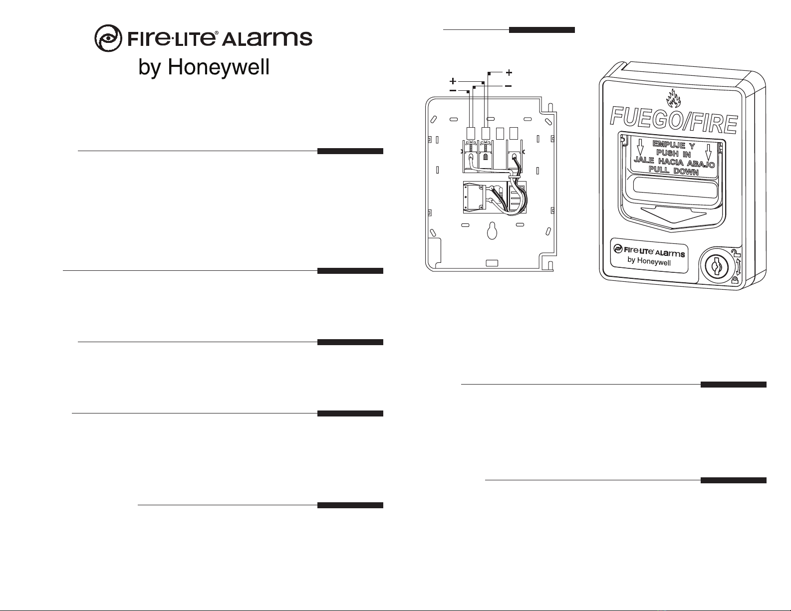
Wiring
CAUTION! Do not detach the door of the pull station during installation. The door of
the pull station cannot be reattached to the backplate after the backplate has already been
installed onto an electrical box.
CAUTION!
Install the Fire•Lite BG-12LXSP addressable pull station in accordance with these instructions,
applicable NFPA standards, national and local Fire and Electrical codes and the requirements
of the AHJ (Authority Having Jurisdiction). Regular testing of the devices should be con-
ducted in accordance with the appropriate NFPA standards. Failure to follow these directions
may result in failure of the device to report an alarm condition. Fire•Lite is not responsible for
devices that have been improperly installed, tested or maintained.
ADA Compliance
For ADA compliance, if the clear oor space only allows forward approach to an object, the
maximum forward reach height allowed is 48 inches (121.92 cm). If the clear oor space
allows parallel approach by a person in a wheelchair, the maximum side reach allowed is
54 inches (137.16 cm).
BG-12LXSP
Addressable Pull Station
(over for Programming information)
Document 52148 I56-3663-001
P0210-02


