TECHNICAL SPECIFICATION
Type Value: 146
System Compatibility: Use only with FC Fire Alarm Controllers
Environment: Indoor Application only
Operating Temperature: -25 to +70 oC
Storage Temperature: -40 to +80 oC
Operating Humidity: Up to 95% non-condensing
Dimensions (HxWxD): 87x148x14mm
Mounting Requirements: One FC backbox surface mount
Battery Requirements:
From Addressable Loop
Class B Standby Current: 0.28mA
From 24V (not including detector
load)
Class B Standby Current: 14.mA
Class B Alarm Current: 50mA for spur
24V Input Power Voltage Requirement:
26.4V max., 21.9V min. This allows for 0.9V max. voltage drop between the
power supply and the FC410DIM
Addressable Device Condi-
tions: – Normal
– Active
– Short Circuit wiring fault
– Open Circuit wiring fault
– PSU fault
– Device Type Invalid
– Device No Response
Detector Circuit:
Min. Detector Voltage: 16V dc
Max. Standby Detector Load per
FC410DIM Circuit: 3mA
Detector Circuit EOL: 4k7W
Max. Circuit Impedance: 50W
Recommended Wire Size: Min. 1.5 mm2Max. 2.5 mm2
INTRODUCTION
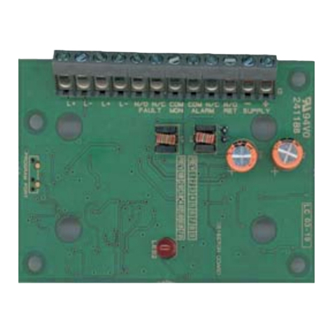
Installation of the FC410DIM comprises the following:
ØInstallation of cables.
ØCable continuity, Insulation and Resistance checks.
ØInstallation of ancillary devices and connection.
The Addressable FC410DIM provides the ability to connect and Interface
one or two zones of 24V dc 2-wire conventional detectors (non-address-
able) to the Fire Alarm Controller.
The FC410DIM monitors the status of detectors and wiring to detectors and
signals detector and wiring status back to the Controller.
FEATURES
The FC410DIM can be configured to:
ØMonitor 1 or 2 Class B spur circuits.
A Monitored Detector going into Alarm, on either spur circuit, will cause
FC410DIM to report the Alarm State back to the Controller.
Status LED provides status of all detectors monitored by the FC410DIM:
ØThe LED is normally off.
ØThe LED turns ON when a detector monitored by the FC410DIM has
gone into Alarm.
ØThe LED will pulse when the Controller polls the FC410DIM.
WIRING & INSTALLATION NOTES
The following notes apply:
1) There are no user-required settings on the FC410DIM.
2) All wiring must conform to the applicable standards.
3) All wiring must be free of earths.
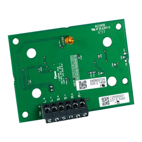
4) Fit the PCB to the FC470CV cover.
5) Connect the wiring for the monitored circuit as shown in wiring diagrams.
6) When monitoring only one Class B circuit, terminate the unused circuit
with the proper EOL resistor.
7) Verify the correct polarity of wiring before connecting FC410DIM to the
addressable loop circuit.
+Refer to Fig.4.
1) If one spur circuit is used , the other circuit must be terminated by 4k7
EOL.
INSTALLATION TO FC470CV ANCILLARY COVER
1) Assemble the FC410DIM to FC470CV Double Gang cover, using the
four screw and washers provided.
2) Fit cover onto FC backbox.
ADDRESS SETTINGS
The FC410DIM has a default factory set address of 255, this must be set to
the loop address of the device using the FC490ST Loop Service Tool. The
FC410DIM may be programmed with the address prior to being installed by
using the internal programming port or after being installed by using the pro-
gramming port on the front cover (see Fig. 2 and Fig.3).
+Note: once the address has been programmed, take note of the device
location and address number, to include on site drawings.
+Note: this device use one address only on the loop.
CABLING
The maximum section of the cable that can be connected at any one termi-
nal is 2.5mm2. The section is calculated based on the characteristics of the
cable and the load.
ORDERING INFORMATION
FC410DIM: Detector Input Module
FC470CV: Double-Gang cover
RECYCLING INFORMATION
Customers are recommended to dispose of their used equipments (panels,
detectors, sirens, and other devices) in an environmentally sound manner.
Potential methods include reuse of parts or whole products and recycling of
products, components, and/or materials.
WASTE ELECTRICAL AND ELECTRONIC EQUIPMENT (WEEE)
DIRECTIVE
In the European Union, this label indicates that this product
should NOT be disposed of with household waste. It should be
deposited at an appropriate facility to enable recovery and re-
cycling.
The manufacturer reserves the right to change the technical specifications
of this product without prior notice.
ENGLISH
www.acornfiresecurity.com
www.acornfiresecurity.com
