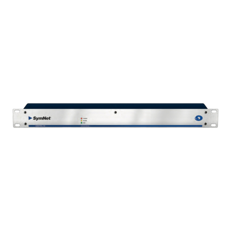
Symetrix Airtools Control I/O User manual

1/11
Quick Start Guide
Control I/O To download the latest version of Studio Matrix Designer, the Windows application
that controls all Studio Matrix hardware, go to: www.airtoolsaudio.com
TM
Symetrix
Engineered by
What Ships in the Box
R A Control I/O hardware device.
R One PS-5 switching power supply
which provides 15 volts DC @ 1.33
amperes. NOTE: The PS-5 will accept
a 100-240 VAC input. A power cable for
domestic use is supplied for the PS-5.
Export customers should supply the
appropriate substitute cable for their
locale.
R This Quick Start Guide.
R
An RJ-45 Incompatibility Warning sheet.
What You Need to Provide
R A Windows PC with 300MHz or higher
Pentium and:
• WIN 98SE, ME, 2000 or XP.
• 10-15 MB free storage space.
• 1024x768 graphics capability.
• 16-bit or higher colors.
• CD-ROM drive or Internet connection.
• 64MB RAM (WIN 98SE/ME), 128MB
RAM (WIN 2000/XP).
R Shielded twisted pair wire to connect
the Control I/O RS-485 port to the
RS-485 port of a master Studio Matrix
audio input or output hardware device.
R CAT-5 cables to connect the Control I/O
to any ARC(s).
R External controls (pots, switches,
encoders, etc.) and hook up wire as
necessary.
Getting Help
Studio Matrix Designer, the Windows
application that controls all Studio Matrix
hardware, includes a help module which
acts as a complete user’s guide for both
hardware (including the Control I/O) and
software. A printable copy is also available
at www.airtoolsaudio.com.
If you have questions beyond the scope
of the help module, contact our Customer
Support Group in the following ways:
Tel (425) 778-7728
8:00 am to 4:30 pm
Monday through Friday,
Pacific Time
Email tech@airtoolsaudio.com
Web www.airtoolsaudio.com
This device complies with part 15 of the FCC
Rules. Operation is subject to the following
two conditions: (1) This device may not cause
harmful interference, and (2) this device must
accept any interference received, including
interference that may cause undesired
operation.
This Class B Digital apparatus meets all
requirements of the Canadian Interference-
Causing Equipment Regulations
Cet appariel numerique de la classe B respecte
toutes les Exigences du Reglement sur le
materiel brouilleur du Canada.
Important Safety
Instructions.
1. Read these instructions.
2. Keep these instructions.
3. Heed all warnings.
4. Follow all instructions.
5. Do not use this apparatus near water.
6. Clean only with dry cloth.
7. Do not block any ventilation open-
ings. Install only in accordance with
the manufacturer’s instructions.
8. Do not install near any heat sources
such as radiators, heat registers,
stoves, or other apparatus (including
amplifiers) that produce heat.
9. Do not defeat the safety purpose of
the polarized or grounding-type plug.
A polarized plug has two blades with
one wider than the other. A grounding
type plug has two blades and a third
grounding prong. The wide blade or
the third prong are provided for your
safety. If the provided plug does not
fit into your outlet, consult an electri-
cian for replacement of the obsolete
outlet.
10. Protect the power cord from being
walked on or pinched particularly at
plugs, convenience receptacles, and
the point where they exit from the
apparatus.
11. Only use attachments/accessories
specified by the manufacturer.
12. Use only with the cart,
stand, tripod, bracket,
or table specified by
the manufacturer, or
sold with the apparatus.
When a cart is used, use caution
when moving the cart/apparatus com-
bination to avoid injury from tip-over.
13. Unplug this apparatus during light-
ning storms or when unused for long
periods of time.
14. Refer all servicing to qualified service
personnel. Servicing is required when
the apparatus has been damaged in
any way, such as power-supply cord
or plug cord is damaged, liquid has
been spilled or objects have fallen
into the apparatus, the apparatus has
been exposed to rain or moisture,
does not operate normally, or has
been dropped.
AVIS:
NE PAS OUVRIR
Il ne se trouve a l’interieur aucune piece pourvant entre reparée l’usager.
SEE OWNERS MANUAL. VOIR CAHIER D’INSTRUCTIONS.
S’adresser a un reparateur compétent.
RISQUE DE CHOC ELECTRIQUE
No user serviceable parts inside. Refer servicing to qualified service personnel.
CAUTION
WARNING:
TO REDUCE THE RISK OF FIRE OR
ELECTRIC SHOCK DO NOT EXPOSE
THIS EQUIPMENT TO RAIN OR MOISTURE
DO NOT OPEN
RISK OF ELECTRIC SHOCK
The lightning flash with arrowhead
symbol within an equilateral triangle is
intended to alert the user of the pres-
ence of uninsulated “dangerous voltage”
within the product’s enclosure that may
be of sufficient magnitude to constitute
a risk of electric shock to persons. The
exclamation point within an equilateral
triangle is intended to alert the user of
the presence of important operating and
maintenance (servicing) instructions in
the literature accompanying the product
(i.e. this Quick Start Guide).
CAUTION To prevent electric shock,
do not use the polarized plug supplied
with the unit with any extension cord,
receptacle, or other outlet unless the
prongs can be fully inserted.
Power Source. AirTools™ Control
I/O hardware uses a switching power
supply that automatically adjusts to the
applied voltage. Ensure that your AC
mains voltage is somewhere between
100-240 VAC, 50-60 Hz. Use only the
power cord and connector specified for
the product and your operating locale.
A protective ground connection, by way
of the grounding conductor in the power
cord, is essential for safe operation.
User Serviceable Parts. There
are no user serviceable parts inside
the AirTools™ Control I/O. In case
of failure, customers inside the U.S.
should refer all servicing to the Syme-
trix factory. Customers outside the U.S.
should refer all servicing to an autho-
rized AirTools distributor. Distributor
contact information is available online at
www.airtoolsaudio.com.
Before You Begin

2/11
Quick Start Guide
Control I/O To download the latest version of Studio Matrix Designer, the Windows application
that controls all Studio Matrix hardware, go to: www.airtoolsaudio.com
TM
Symetrix
Engineered by
3/11
Quick Start Guide
Control I/O To download the latest version of Studio Matrix Designer, the Windows application
that controls all Studio Matrix hardware, go to: www.airtoolsaudio.com
TM
Symetrix
Engineered by
Overview
The Control I/O is a 1 rack space AirTools Studio Matrix system accessory which allows the system to control and be controlled
from various external devices. The Control I/O serves to expand and augment a system’s capabilities. Additionally, the Control
I/O provides a MIDI gateway to the system allowing the use of low-cost generic MIDI controllers for control of almost any DSP
parameter. The Control I/O also provides a generic ASCII command protocol which allows it to be used in a stand-alone fashion
or integrated into other RS-485 compatible control systems such as those made by AMX or Crestron.
Front Panel
Item Description What It Does
POWER Red LED Indicates that the unit is powered on.
RS-485 COMM Yellow LED Indicates active RS-485 communications.
MIDI COMM Green LED Indicates active MIDI communications.
Rear Panel
Item Description What It Does
POWER INPUT 4 pin XLR jack Accepts power from a Symetrix PS-5 switching power supply (15 VDC @ 1.33 A).
DEVICE CONFIG 8 DIP switch block Configures the Control I/O’s device address (0-31). Addressing is done in a binary
fashion. (See Device Address Quick Reference).
RS-485 Euroblock Connects to the Primary Studio Matrix hardware device at ADDR #1 or 3rd party
RS-485 compatible controller.
MIDI I/O Female DB15 Allows external MIDI control via a standard DB15 “joystick” to (2) DIN 5 MIDI IN
and MIDI OUT cables adapter. (Adapter not included).
REMOTE ARCs 4 x RJ-45 Distributes power and RS-485 data to one or more ARCs per port.
(See ARC Network Design)
RELAY OUTPUTS Euroblocks 4 x SPDT relays rated at 3A, 24VDC, resistive; 0.3A, 60VDC, resistive and can be
wired normally open or normally closed.
OPEN COLLECTOR OUTPUTS
Euroblocks 8 x open collector outputs with paired common ground pins. OC outputs go low
(0V) when active, and are internally pulled high (5V) when inactive and can drive
external LED indicators directly.
ANALOG CONTROL INPUTS Euroblocks 8 x analog control inputs able to be used as 8 potentiometer inputs, 8 mechanical
rotary encoder inputs, or as 16 switch inputs (+5 VDC reference voltage supplied).
Control I/O connections to AirTools Studio Matrix system
The Control I/O connects to any Primary Studio Matrix hardware device at ADDR #1 (any Ring). This would be any Studio
Matrix audio I/O device in the system with a device address of 1 in the Primary position. The Control I/O connects via the RS-
485 ports using shielded twisted pair cable wired in parallel.
Note: when a redundant pair is at address 1, the RS-485 bus should be wired in parallel to both the Primary and Secondary units.
Warning! DO NOT plug the RJ-45 connectors labeled “REMOTE ARCs” into any RJ-45 connector labeled “SYMLINK”,
“HOMERLINK” or “ETHERNET”.
Overview, Front Panel, Rear Panel, System Connection
Control I/O
RS-485 COMM
POWER
MIDI COMM
Studio Matrix
SYSTEM STATUS
POWER INPUT
15-24VDC�
20W MAX
MANUFACTURED BY SYMETRIX, INC. MTLK TERR, WA
THIS UNIT CONTAINS NO USER SERVICEABLE PARTS
FABRIQUÉ AUX E.-U. PAR SYMETRIX, INC. MTLK TERR, WA
PAS DES ELEMENTS SERVIABLE PAR UTILISATEUR
POWER INPUT
ASCII / AirTools
UPGRADE / RUN
RESERVED
RS-485
ADDR
RS-485 RELAY OUTPUTS OPEN COLLECTOR OUTPUTS
ANALOG CONTROL INPUTS - SWITCH / POT / ENCODER
REMOTE ARCs
4
MIDI I/O
3 2 1 C NC
4
NO C NC NO C NC NO C NC NO
DEVICE CONFIG
1 2 4 8 16
B A
3
2
1
8
7
6
5
4
3
2
1
8 7 6 5 4 3 2 1
B A B A B A B A
B A B A B A B A
+5V
+5V
+5V
+5V
+5V
+5V
+5V
+5V
CONTROL I/O
Engineered By
www.airtoolsaudio.com

2/11
Quick Start Guide
Control I/O To download the latest version of Studio Matrix Designer, the Windows application
that controls all Studio Matrix hardware, go to: www.airtoolsaudio.com
TM
Symetrix
Engineered by
3/11
Quick Start Guide
Control I/O To download the latest version of Studio Matrix Designer, the Windows application
that controls all Studio Matrix hardware, go to: www.airtoolsaudio.com
TM
Symetrix
Engineered by
Analog Control Input Wiring
The following illustrations show the connection of either a 10k ohm linear potentiometer, a mechanical rotary encoder or
switches to one of the 8 analog control inputs of Control I/O. (Please see the Studio Matrix Designer online help for information
on how to assign an analog control input to a Studio Matrix DSP parameter.)
The Symetrix model RC-3 is the perfect potentiometer match for the Control I/O. Suitable potentiometers, switches and
encoders might also be sourced from electronic parts suppliers such as Digi-key. Note that encoders must be of the mechanical
type.
Disclaimer: From time to time we test the compatibility of our own products with those of third parties. While we are happy to
share with our customers the results of our own studies as well as other possibly unsubstantiated information regarding these
third party products, it is the policy of Symetrix, Inc. to neither endorse, recommend nor support products manufactured and/or
supplied by third parties. The responsibility of choosing third party products which are compatible with Symetrix products rests
solely with the qualified contractor, consultant or system designer.
Open Collector Output Wiring
The following illustrations depict three typical open collector output hook ups. The most common uses for the open collector
outputs are to fire external LED indicators (LED lit when OC inactive) or drive external relays. (Please see the Studio Matrix
Designer online help for information on how to address an Open Collector output in a Studio Matrix DSP design.)
Analog Control Input and Open Collector Output Wiring
Euroblock
2C Shielded Twisted Pair
10kohm
Linear
Taper
Pot
+5V (OUT)
INPUT
GND
T
ypical Control Potentiometer Wiring
Euroblock
A
B
GND
Typical Control Switch Wiring for Discrete Switch Inputs
Switch 1
Switch 2
Euroblock
A
B
GND
Typical Mechanical Rotary Encoder Wiring
A or +ve
B or -ve
Encoder
GND
1. Self-Sourcing
LED Drive
Internal External
Note: You do not need
to supply the
components on the
"Internal" side. These
components are internal
to the Control I/O and
only illustrated here for
the purpose of under-
standing the operation
of the circuit.
Open Collector
Output
to OC output
LED
GND
+5 VDC
0V
221 ohm
10 ohm
PZTA06
1N4003
Ferrite Bead
1N914
2. External Relay Drive
to OC output
Relay
External Relay Supply
(24 VDC Max)
50 mA Max
coil current
1N4004
+V from
external supply
3. External LED drive using
external supply for
more current
to OC output LED

4/11
Quick Start Guide
Control I/O To download the latest version of Studio Matrix Designer, the Windows application
that controls all Studio Matrix hardware, go to: www.airtoolsaudio.com
TM
Symetrix
Engineered by
5/11
Quick Start Guide
Control I/O To download the latest version of Studio Matrix Designer, the Windows application
that controls all Studio Matrix hardware, go to: www.airtoolsaudio.com
TM
Symetrix
Engineered by
Relay Outputs
The Control I/O provides four (4) SPDT relay contacts. Common, Normally Closed and Normally Open pins are furnished on
Euroblock connectors. Contact ratings for the relays are: 3A, 24VDC, resistive; 0.3A, 60VDC, resistive. Do not use at 120 VAC.
(Please see the Studio Matrix Designer online help for information on how to address a Relay Output in a Studio Matrix DSP
design.)
Remote ARCs
The four (4) REMOTE ARC ports distribute power and RS-485 data to one or more ARCs arranged in one or more chains over
standard CAT-5 cable. The Control I/O can support up to eight (8) ARCs total within the guidelines set forth in the ARC Network
Design section. (Please see the Studio Matrix Designer online help for information on how to program the ARC.)
Warning! The RJ-45 connectors labeled “REMOTE ARCs” are only for use with the ARC controllers. Do not plug these
connections into any SymLink, HomerLink or Ethernet connector or into an ARC-PS or even another Control I/O!
ARC Network Design
The ARC’s power requirements vary depending on the voltage supplied to it. At 15V DC, it uses approximately 115 mA, while at
6V DC it uses approximately 300 mA maximum. As the voltage goes from 15V DC to 6V DC, the current requirement increases
accordingly.
ARCs can be daisy-chained and fed power over this daisy-chain from the Control I/O. However, as the length of the cable
increases, so does the resistive line loss, which lowers the voltage available at each subsequent ARC. The actual power drain
on each output from the Control I/O can vary substantially depending on the number of ARCs and the distance each of them
is separated by. In order to assist with system design, Symetrix has available a Microsoft Excel spreadsheet that can help a
system designer determine power requirements based upon cable length, number of ARCs and the power supply to be used.
This spreadsheet can be downloaded from the SymNet Technical Support pages at:
http://www.symetrixaudio.com/SymNet_Web/index.htm
Relay Outputs, Remote ARCs, ARC Network Design
The following table gives some indication of cabling
limitations, based on DC power only (the table is not relevant
if only RS-485 is distributed via the Control I/O): minimum
stated distances assume 28 gauge CAT-5 cabling, maximum
stated distances assume 24 gauge CAT-5 cabling.
CABLE LENGTH LIMITATIONS FOR ARC DC POWER
OVER CAT-5 CABLE
Total cable length
(to end of chain)
Number of ARCs in 1 daisy
chain
224-640 ft. 4
276-792 ft. 3
350-1028 ft. 2
486-1396 ft. 1
If power is not distributed over CAT-5, the ARC’s RS-485 will
be limited to 1000 ft in a star network configuration and 4000
ft in a daisy-chain network configuration. Longer distances
may be possible using third party RS-485 extender products.
Connections
The RS-485 port on the back of any Ring Master Studio
Matrix hardware device at ADDR #1 should be connected
to the RS-485 port on the Control I/O using shielded twisted
pair cable wired in parallel. Then, CAT-5 cable should be
distributed amongst the ARCs in the system preferably in a
star configuration or in minimal daisy chains according to the
limitations outlined previously. Finally, power can be applied
to the Control I/O and programming may commence.
CAT-5 CABLE PINOUT FOR POWER AND RS-485 DISTRIBUTION
Pin # Function
1 Ground
2 Ground
3 Ground
4 RS-485 “A”
5 RS-485 “B”
6 Ground
7 Power
8 Power
WARNING: When designing a system, one must be careful
not to double power any ARCs. If all pins on the CAT-5
connections are used, power can travel over the CAT-5 cable
and reach any ARC on that particular chain. So, power over
CAT-5 could potentially come from the Control I/O or from an
ARC that is powered locally and then daisy chained via CAT-
5 to other ARCs. In general, it is recommended to use only
one type of connector on the ARCs, either the RJ-45s (with
CAT-5 cable) or the terminal blocks.

4/11
Quick Start Guide
Control I/O To download the latest version of Studio Matrix Designer, the Windows application
that controls all Studio Matrix hardware, go to: www.airtoolsaudio.com
TM
Symetrix
Engineered by
5/11
Quick Start Guide
Control I/O To download the latest version of Studio Matrix Designer, the Windows application
that controls all Studio Matrix hardware, go to: www.airtoolsaudio.com
TM
Symetrix
Engineered by
RS-485 Termination
Both the ARC and the Control I/O feature an RS-485 termination jumper. Jumper J17 inside the Control I/O by the RS-485 jack
enables and disables termination. Jumping pins 1 and 2 = terminated, pins 2 and 3 = open. For maximum signal integrity, follow
the termination guidelines below:
RS-485 TERMINATION GUIDELINES
Daisy chain length Termination
0 - 200 ft. No termination required
200 - 1000 ft. (if powering over CAT-5) Terminate at Control I/O
> 1000 ft. (or if not powering over CAT-5) Terminate at Control I/O and at the last ARC in each chain
For star configurations, terminate at the Control I/O.
MIDI I/O
With the DB15 MIDI I/O “joystick” port, the Control I/O can function as a MIDI Continuous Controller (CC) to RS-485 Controller
translator. The DB15 port uses a standard to (2) DIN 5 MIDI IN and MIDI OUT cable adapter. (Adapter not included). The
adapter is the same that most all computer sound cards with a joystick port use and is available at many computer and music
supply outlets. (Please see the Studio Matrix Designer online help for information on how to map a MIDI Controller number to an
RS-485 Controller number in a Studio Matrix DSP design.)
Device Address Quick Reference
Every RS-485 device (including all ARCs and Control I/Os) connected to the same Studio Matrix Ring must be uniquely
identified. You may use the pictorial diagrams below to quickly set up and understand the device address DIP switches on the
Control I/O. Any time the DIP switches are changed, the unit must be power cycled for the changes to take effect.
Note: The Control I/O contains field-upgradable firmware. Upgrading is facilitated by DIP switch #2 labeled “UPGRADE / RUN”.
Unless instructed by Symetrix Technical Support personnel or a Symetrix Technical Bulletin, this switch should remain in the
“RUN” position.
RS-485 Termination, MIDI I/O, Device Address Quick Reference
Control I/O DIP Switch Settings
NOTE: For the sake of space, only switch settings for the first 8 addresses are pictured.
An address of up to 31 is possible (all DIP switches down). For systems containing
32 total Control I/O's, an address of zero (0) is available (all DIP switches UP).
Address 1 Address 2 Address 4
ASCII / SYMNET
UPGRADE / RUN
RESERVED
RS-485
ADDR
1 2 4 8 16
ASCII / SYMNET
UPGRADE / RUN
RESERVED
RS-485
ADDR
1 2 4 8 16
Address 3
ASCII / SYMNET
UPGRADE / RUN
RESERVED
RS-485
ADDR
1 2 4 8 16
ASCII / SYMNET
UPGRADE / RUN
RESERVED
RS-485
ADDR
1 2 4 8 16
Address 5 Address 6 Address 8
ASCII / SYMNET
UPGRADE / RUN
RESERVED
RS-485
ADDR
1 2 4 8 16
ASCII / SYMNET
UPGRADE / RUN
RESERVED
RS-485
ADDR
1 2 4 8 16
Address 7
ASCII / SYMNET
UPGRADE / RUN
RESERVED
RS-485
ADDR
1 2 4 8 16
ASCII / SYMNET
UPGRADE / RUN
RESERVED
RS-485
ADDR
1 2 4 8 16

6/11
Quick Start Guide
Control I/O To download the latest version of Studio Matrix Designer, the Windows application
that controls all Studio Matrix hardware, go to: www.airtoolsaudio.com
TM
Symetrix
Engineered by
7/11
Quick Start Guide
Control I/O To download the latest version of Studio Matrix Designer, the Windows application
that controls all Studio Matrix hardware, go to: www.airtoolsaudio.com
TM
Symetrix
Engineered by
Stand-alone Operation
The Control I/O may also be used in a stand-alone fashion or integrated into other RS-485 compatible control systems such as
those made by AMX or Crestron. All previous hook up information applies as well as device addressing information (with the
exception of DIP switch #1 “ASCII / Studio Matrix”, which should be down in the “ASCII” position and then the unit power cycled
to enable stand-alone mode). The REMOTE ARC ports will not be of use in this application as the ARCs do not use the protocol
outlined below.
ASCII Control Protocol
Introduction
The Control I/O has the capability of being used as a generic control device, without the Studio Matrix system being present. In
this mode, the device accepts generic commands from the RS-485 input and respond accordingly. This section outlines how that
is accomplished, and the commands supported by the device.
Control I/O Setup
Setting the second DIP switch from the left (looking from the rear) to the ‘on’ (down) position puts the Control I/O into the ASCII
control mode. After changing modes, the unit will need to be power cycled for the setting to take effect. While in the ASCII
control mode, the unit will not respond to normal Studio Matrix commands, but instead to a simple ASCII based protocol suitable
for AMX/Crestron type controllers or even a simple terminal program.
Command Set
The <address> field must match the value of the address on the specific unit’s DIP switch. If the address field does not
match, then the command is ignored and no response is sent which allows multiple units to reside on the same RS-485 bus.
If the address is correct but the command isn’t recognized, or any of the parameters are incorrect, a NAK will be returned.
The address field can range from 0-31. If everything was satisfactory, an ACK will be returned. Parameter values can be
separated by space(s) or a comma, though numeric parameters directly following a character value need no delimination. All
numeric parameters are positive decimal integers except for the Send MIDI String command which accepts a string of two digit
hexadecimal numbers.
(FU) Flash Front LEDs
Command:
FU <address><cr>
Where <address> is a decimal number 0-31.
Response:
<ACK/NAK><cr>
(RV) Return Software Version
Returns the current firmware version of the Control I/O’s microcontroller.
Command:
RV <address><cr>
Response:
<value> <ACK/NAK><cr>
Where <value> is the version number times 100.
(IM) Set Input Mode
Command:
IM <address> <input> <mode><cr>
Where <input> is a decimal number 1-8 and <mode> is:
P = potentiometer
E = encoder
S = dual switch
Note: Input modes are persistent with power cycling. A new unit from the factory will set all 8 inputs as dual switches.
Response:
<ACK/NAK><cr>
If <input> is outside the 1-8 range, or <mode> is not “P”, “E”, or “S” then a “NAK” is returned.
Stand-alone Operation, ASCII Control Protocol

6/11
Quick Start Guide
Control I/O To download the latest version of Studio Matrix Designer, the Windows application
that controls all Studio Matrix hardware, go to: www.airtoolsaudio.com
TM
Symetrix
Engineered by
7/11
Quick Start Guide
Control I/O To download the latest version of Studio Matrix Designer, the Windows application
that controls all Studio Matrix hardware, go to: www.airtoolsaudio.com
TM
Symetrix
Engineered by
(RI) Read Input State
Reads the state of the analog control inputs.
Command:
RI <address> <input><cr>
Where <input> is a decimal number 1-8.
Response:
<value> <ACK/NAK><cr>
If the input is a pot, <value> is always returned as 3 decimal digits with a range of 000-255.
000 = pot arm at ground
255 = pot arm at max
If the input is an encoder, <value> is always returned as 3 decimal digits with a range of 000-255. The step size is assumed
as 1. Encoder range can be limited with the EN and EX commands. When used as encoder inputs, the analog control inputs
feature a built in acceleration function to speed large changes.
If the input is a dual switch, <value> is:
000 = No switches on
001 = Lower (A) switch on
010 = Upper (B) switch on
011 = Both switches on
Note: If <input> is outside the 1-8 range, a NAK is returned along with a <value> of 0. If the port mode wasn’t previously
set up, a “NAK” is returned along with a <value> of 0.
(SO) Set Open Collector Initial Value
Allows the powerup value of the open collectors to be set. This is useful for initializing the open collector outputs to a given state
on powerup.
Command:
SO <address> <output> <state><cr>
Where <output> is a decimal number 1-8 and <state> is 0 for off and 1 or greater for on. When the open collector is off,
the voltage at the open collector is pulled high to 5 volts allowing an attached LED to light. When the open collector driver is on,
there is a low impedance between the output and ground connections allowing an external load to sink current.
Response:
<ACK/NAK><cr>
If <value> is greater than 255 or <input> is outside the 1-8 range, a “NAK” is returned. This value is saved and restored
on powerup.
(OC) Open Collector Output Control
Turns open collector outputs on (active low) or off (tristate, normally pulled high). These outputs first initialize to off (high),
however this initial state can be changed with the Set Open Collector Initial Value command.
Command:
OC <address> <output> <state><cr>
Where <output> is a decimal number 1-8 and <state> is 0 for off and 1 or greater for on. When the open collector is off,
the voltage at the open collector is pulled high to 5 volts allowing an attached LED to light. When the open collector driver is on,
there is a low impedance between the output and ground connections allowing an external load to sink current.
Response:
<ACK/NAK><cr>
ASCII Control Protocol... continued

8/11
Quick Start Guide
Control I/O To download the latest version of Studio Matrix Designer, the Windows application
that controls all Studio Matrix hardware, go to: www.airtoolsaudio.com
TM
Symetrix
Engineered by
9/11
Quick Start Guide
Control I/O To download the latest version of Studio Matrix Designer, the Windows application
that controls all Studio Matrix hardware, go to: www.airtoolsaudio.com
TM
Symetrix
Engineered by
(SR) Set Relay Initial Value
Allows the powerup value of the relays to be set. This is useful for initializing the relays to a given state on powerup.
Command:
SR <address> <relay> <state><cr>
Where <relay> is a decimal number 1-4 and <state> is 0 for off and 1 or greater for on. An off state of the relay
corresponds to the NC of the relay connector being connected to the common (C) connection. An on state corresponds to the NO
of the relay connector being connected to the common (C) connection.
Response:
<ACK/NAK><cr>
If <value> is greater than 255 or <input> is outside the 1-4 range, a “NAK” is returned. This value is saved and restored
on powerup.
(RC) Relay Control
Turns relays on or off. These outputs first initialize to off, however this initial state can be changed with the Set Relay Initial
Value command.
Command:
RC <address> <relay> <state><cr>
Where <relay> is a decimal number 1-4 and <state> is 0 for off and 1 or greater for on. An off state of the relay
corresponds to the NC of the relay connector being connected to the common (C) connection. An on state corresponds to the NO
of the relay connector being connected to the common (C) connection.
Response:
<ACK/NAK><cr>
(SE) Set Internal Encoder Initial Value
Allows the powerup value of the internal encoders to be set. This is useful for initializing the encoders to a given state on
powerup.
Command:
SE <address> <input> <value><cr>
Where <input> is a decimal number 1-8 and <value> is 0-255.
Response:
<ACK/NAK><cr>
If <value> is greater than 255 or <input> is outside the 1-8 range, a “NAK” is returned. This value is saved and restored
on powerup.
(EN) Set Internal Encoder Minimum Value
Allows the minimum value of the internal encoders to be set. This is useful for restricting the range of the encoder input(s).
Command:
EN <address> <input> <value><cr>
Where <input> is a decimal number 1-8 and <value> is 0-255.
Response:
<ACK/NAK><cr>
If <value> is greater than 255 or <input> is outside the 1-8 range, a “NAK” is returned. This value is saved and restored
on powerup. If the minimum encoder value is set greater than the maximum encoder value, anomalous operation will occur.
ASCII Control Protocol... continued

8/11
Quick Start Guide
Control I/O To download the latest version of Studio Matrix Designer, the Windows application
that controls all Studio Matrix hardware, go to: www.airtoolsaudio.com
TM
Symetrix
Engineered by
9/11
Quick Start Guide
Control I/O To download the latest version of Studio Matrix Designer, the Windows application
that controls all Studio Matrix hardware, go to: www.airtoolsaudio.com
TM
Symetrix
Engineered by
ASCII Control Protocol... continued
(EX) Set Internal Encoder Maximum Value
Allows the maximum value of the internal encoders to be set. This is useful for restricting the range of the encoder input(s).
Command:
EX <address> <input> <value><cr>
Where <input> is a decimal number 1-8 and <value> is 0-255.
Response:
<ACK/NAK><cr>
If <value> is greater than 255 or <input> is outside the 1-8 range, a “NAK” is returned. This value is saved and restored
on powerup. If the maximum encoder value is set less than the minimum encoder value, anomalous operation will occur.
(MC) Return MIDI Control Changed
Used to determine if one or more MIDI controllers have changed value.
Command:
MC <address><cr>
Response:
<value> <ACK/NAK><cr>
Where <value> is 0-127. If the value is 0, no MIDI values have changed since the last poll, else the MIDI controller
number 1-127 that has changed will be returned. Each poll will return the lowest numbered changed controller until all the
changed parameters have been reported. Only MIDI channel 1 is decoded (where lower nibble = 0 in the MIDI control change
command byte) A typical poll sequence would be:
If (Ctrl = MC<addr>) != 0 then Value = RM<addr> <Ctrl>
(RM) Read MIDI Input Value
Allows an external MIDI input to be read by an RS-485 controller.
Command:
RM <address> <controller><cr>
Where <controller> is a decimal number 1-127.
Response:
<value> <ACK/NAK><cr>
Where <value> is a decimal number 0-127.
If <controller> is outside the 1-127 range, a “NAK” is returned along with a value of 0. Only MIDI channel 1 is decoded
(where lower nibble = 0 in the MIDI control change command byte).
(SM) Send MIDI String
Allows MIDI strings to be sent to the Control I/O via RS-485, then output on the MIDI out connector. Note: the maximum string
length is 512 MIDI characters including all delimiters. Longer strings must be sent using multiple invocations of the command.
The data is in decimal format. The string is stored until the <cr> is received, then sent out in one block.
Command:
SM <address> <$data byte 1>...<$data byte n><cr>
Response:
<ACK/NAK><cr>

11/11
Quick Start Guide
Control I/O To download the latest version of Studio Matrix Designer, the Windows application
that controls all Studio Matrix hardware, go to: www.airtoolsaudio.com
TM
Symetrix
Engineered by
Warranty and Service
The AirTools Limited Warranty
Symetrix, Inc. expressly warrants that the product will be free
from defects in material and workmanship for eighteen (18)
months from the date the product is shipped from the factory.
Symetrix's obligations under this warranty will be limited to
repairing or replacing, at Symetrix's option, the part or parts
of the product which prove defective in material or workman-
ship within eighteen (18) months from the date the product
is shipped from the factory, provided that the Buyer gives
Symetrix prompt notice of any defect or failure and satisfac-
tory proof thereof. Products may be returned by Buyer only
after a Return Authorization number (RA) has been obtained
from Symetrix. Buyer will prepay all freight charges to return
the product to the Symetrix factory. Symetrix reserves the
right to inspect any products which may be the subject of any
warranty claim before repair or replacement is carried out.
Symetrix may, at its option, require proof of the original date of
purchase (dated copy of original retail dealer's invoice). Final
determination of warranty coverage lies solely with Symetrix.
Products repaired under warranty will be returned freight
prepaid via United Parcel Service by Symetrix, to any location
within the Continental United States. Outside the Continental
United States, products will be returned freight collect.
The foregoing warranties are in lieu of all other warran-
ties, whether oral, written, express, implied or statutory.
Symetrix, Inc. expressly disclaims any IMPLIED warran-
ties, including fitness for a particular purpose or mer-
chantability. Symetrix's warranty obligation and buyer's
remedies hereunder are SOLELY and exclusively as
stated herein.
This Symetrix AirTools product is designed and manufactured
for use in professional and studio audio systems and is not
intended for other usage. With respect to products purchased
by consumers for personal, family, or household use, Syme-
trix expressly disclaims all implied warranties, including
but not limited to warranties of merchantability and fit-
ness for a particular purpose.
This limited warranty, with all terms, conditions and disclaim-
ers set forth herein, shall extend to the original purchaser and
anyone who purchases the product within the specified war-
ranty period.
Symetrix does not authorize any third party, including any
dealer or sales representative, to assume any liability or make
any additional warranties or representation regarding this
product information on behalf of Symetrix.
This limited warranty gives the buyer certain rights. You may
have additional rights provided by applicable law.
Note: Some Symetrix AirTools products contain embedded
software and may also be accompanied by control software
intended to be run on a personal computer. Said software is
specifically excluded from this warranty.
Limitation of Liability
The total liability of Symetrix on any claim, whether in contract,
tort (including negligence) or otherwise arising out of, con-
nected with, or resulting from the manufacture, sale, delivery,
resale, repair, replacement or use of any product will not
exceed the price allocatable to the product or any part thereof
which gives rise to the claim. In no event will Symetrix be liable
for any incidental or consequential damages including but not
limited to damage for loss of revenue, cost of capital, claims
of customers for service interruptions or failure to supply,
and costs and expenses incurred in connection with labor,
overhead, transportation, installation or removal of products,
substitute facilities or supply houses.
Servicing the Control I/O
If you have determined that your Control I/O requires repair
services and you live outside of the United States please con-
tact your local AirTools dealer or distributor for instructions on
how to obtain service. If you reside in the U.S. then proceed
as follows.
Return authorization
At the Symetrix factory, Symetrix will perform in-warranty or
out-of-warranty service on any product it has manufactured for
a period of three (3) years from date of discontinued manufac-
ture.
Before sending anything to Symetrix, please contact our
Customer Service Department for a return authoriza-
tion (RA) number. The telephone number is (425) 778-
7728. Additionally support is available via E-mail through
[email protected] or via the web site
http://www.airtoolsaudio.com.
In-warranty repairs
To get your Control I/O repaired under the terms of the war-
ranty:
1. Call us for an RA number (have the serial number, ship-
ping and contact information and description of the problem
ready).
2. Pack the unit in its original packaging materials.
3. Include your name, address, daytime telephone number,
and a brief statement of the problem.
4. Write the RA number on the outside of the box.
5. Ship the unit to Symetrix, freight prepaid. We do not accept
freight collect shipments.
Just do these five things, and repairs made in-warranty will
cost you only one way freight charges. We'll pay the return
freight.
If you don't have the factory packaging materials, we rec-
ommend using an oversize box. Wrap the unit in a plastic
bag, surround it with bubble-wrap, and place it in the box
surrounded by Styrofoam peanuts. Be sure there is enough
clearance in the box to protect the rack ears. We won't return
the unit in anything but Symetrix packaging for which we will
have to charge you. If the problem is due to operator misuse
or error, you will have to pay for both parts and labor. In any
event, if there are charges for the repair, you will pay for the
return freight. All charges will be COD unless you have made
other arrangements (prepaid, Visa or Mastercard).
Out-of-warranty repairs
If the warranty period has passed, you'll be billed for all neces-
sary parts, labor, packaging materials, and freight charges.
Please remember, you must call for an RA number before
sending the unit to Symetrix.
© 2003, Symetrix, Inc. All rights reserved. Printed in the United States of America. Symetrix Part Number 53CIOA-1A00. The information in this Quick
Start Guide is subject to change without notice. Symetrix, Inc. shall not be liable for technical or editorial errors or omissions contained herein; nor is
it liable for incidental or consequential damages resulting from the furnishing, performance, or use of this material. Mention of third-party products is
for informational purposes only and constitutes neither an endorsement nor a recommendation. Symetrix assumes no responsibility with regard to the
performance or use of these products. Under copyright laws, no part of this Quick Start Guide may be reproduced or transmitted in any form or by any
means, electronic or mechanical, without permission in writing from Symetrix, Inc. If, however, your only means of access is electronic, permission
to print one copy is hereby granted. Product names mentioned herein may be trademarks and/or registered trademarks of their respective owners.
Table of contents
Other Symetrix Control Unit manuals
Popular Control Unit manuals by other brands

Zamel
Zamel Exta LDM-11 Manual instruction

Telit Wireless Solutions
Telit Wireless Solutions WE866E4-P AT Commands Reference Guide

Watts Industries
Watts Industries Powers HydroGuard e420 Series Technical instructions

aquabrass
aquabrass 1010 Installation procedures

Crosswater
Crosswater WLBP3001R Plus installation instructions

Spirax Sarco
Spirax Sarco ABV21i Installation and maintenance instructions

Linear Technology
Linear Technology DC1453A Demo Manual

Allen-Bradley
Allen-Bradley POINT I/O 1734-ADN installation instructions

H3C
H3C LSVM152SCFAN user manual

WAGO
WAGO 750-494 Series manual

Honeywell
Honeywell Ex-Or CDH4U5 Installation and commissioning instructions

Sound Devices
Sound Devices SL-2 user guide