Firehawk M7XT User manual
FireHawk®M7XT
Air Mask
NFPA 1981: 2013 Edition
NFPA 1982: 2013 Edition (Integrated PASS Version Only)
CBRN Agent Approved Air Mask
OPERATION AND INSTRUCTIONS
This device complies with Part 15 of the FCC Rules. Operation is subject to the following conditions:
(1) This device may not cause harmful interference and (2) this device must accept any interference that may cause undesired
operation.
MSA 2211 (L) Rev. 8 © MSA 2017, 2022
This manual must be carefully read and followed by all persons who have or will have the responsibility for using or servicing
this air mask. This air mask will perform as designed only if used and serviced according to the instructions; otherwise it could
fail to perform as designed, and persons who rely on the air mask could sustain serious personal injury or death.
This Self-Contained Breathing Apparatus (SCBA) is certified by the National Institute of Occupational Safety and Health (NIOSH).
See supplement P/N 10145467 for NIOSH approval information.
Changes and modifications not expressly approved by the manufacturer could void the user’s authority to operate the equipment.
Use in conjunction with personal protective ensembles that provide appropriate levels of protection against dermal hazards.
Some CBRN agents may not present immediate effects from exposure, but can result in delayed impairment, illness, or death.
Direct contact with CBRN agents requires proper handling of the SCBA after each use and between multiple entries during the same use.
Decontamination and disposal procedures must be followed. If contaminated with liquid chemical warfare agents,
dispose of the SCBA after contamination.
The respirator should not be used beyond 6 hours after initial exposure to chemical warfare agents to avoid possibility of agent perme-
ation.
FAILURE TO FOLLOW THE ABOVE ITEMS IN ADDITION TO ALL ESTABLISHED CBRN PROTECTIVE MEASURES CAN RESULT IN SERIOUS PER-
SONAL INJURY OR DEATH.
The warranties made by MSA with respect to the product are voided if the product is not installed, used and serviced in
accordance with the instructions in this manual. Please protect yourself and your employees by following the instructions.
Please read and observe the WARNIN S and CAUTIONS inside. For any additional information relative to use or repair, write or call 1-
877-MSA-FIRE (672-3473) during regular working hours.
"!
WARN NG
"!
DANGER
Prnt. Spec. 10000005389(A) Mat. 10128861
CR: 800000052505 Doc. 10128861

2
NTRODUCT ON
N OSH APPROVAL NFORMAT ON
CAUT ONS AND L M TAT ONS
I- Contains Electrical parts that may cause an ignition in flam-
mable or explosive atmospheres.
J- Failure to properly use and maintain this product could result
in injury or death.
M- All approved respirators shall be selected, fitted, used and
maintained in accordance with MSHA, OSHA and other
applicable regulations.
N- Never substitute, modify, add or omit parts. Use only exact
replacement parts in the configuration as specified by the
manufacturer.
O- Refer to Users Instructions, and/or maintenance manuals for
information on use and maintenance of these
respirators.
S- Special or critical User’s Instructions and/or specific use limi-
tations apply. Refer to user instructions before
donning.
CAUT ONS AND L M TAT ONS OF USE FOR CBRN SCBA
Q- Use in conjunction with personal protective ensembles that
provide levels of protection against dermal hazards.
R- Some CBRN agents may not present immediate effects from
exposure, but can result in delayed impairment, illness, or
death.
T- Direct contact with CBRN agents requires proper handling of
the SCBA after each use and between multiple entries during
the same use. Decontamination and disposal procedures
must be followed. If contaminated with liquid chemical war-
fare agents, dispose of the SCBA after decontamination.
U- The respirator should not be used beyond 6 hours after initial
exposure to chemical warfare agents to avoid possibility of
agent permeation.
CAUT ONS AND L M TAT ONS OF EMERGENCY BREATH NG
SUPPORT SYSTEMS (EBSS)
• Activation or engagement of EBSS in either the donor or
receiver mode changes the SCBA use to Escape-Only,
approved service time for either the donor, or the receiver
is no longer applicable.
• EBSS may not be engaged or activated in donor mode
after the donor End-of-Service-Time-Indicator (EOSTI) has
activated.
• Users must be fully trained in the operation of EBSS in
accordance with a training program conforming to the
requirements of NFPA Standards 1404, Fire Service
Respiratory Protection Training and 1500, Fire Department
Occupational Safety and Health Program.
• Simultaneous connection of more than two users, one
donor and one receiver, is not permitted.
• SCBAs operated in EBSS mode are approved for escape
only.
• Entry approval only restored after re-charge, either host or
donor.
• Connection not to be established after donor/host EOSTI
activation.
• Limited to one donor/receiver (host/parasite) pair.
• Not suitable for connection in CBRN environment.
S - SPEC AL OR CR T CAL USER’S NSTRUCT ONS
Approved for use at temperatures above -25°F. Approved only
when the compressed-air container is fully charged with air
meeting the requirements of the Compressed as Association
Specification -7 for quality verification level (grade) D air or
equivalent specifications. In fire service applications, MSA recom-
mends breathing air quality in accordance with NFPA 1989,
Standard on Breathing Air Quality for Emergency Services
Respiratory Protection. The cylinder shall meet applicable DOT
specifications.
MSA2211 (L) Rev. 8 - 10128861
TABLE OF CONTENTS
NIOSH Approval Information . . . . . . . . . . . . . . . . . . . . . . . . . . . . . . . . . . . . . . . . . . . . . . . . . . . . . . . . . . . . . . . . . . . . . . . . . . . . . . . . . . . . . . . . . . . . . . . . . . . . . . . . . . . .2
Special or Critical Users Instructions . . . . . . . . . . . . . . . . . . . . . . . . . . . . . . . . . . . . . . . . . . . . . . . . . . . . . . . . . . . . . . . . . . . . . . . . . . . . . . . . . . . . . . . . . . . . . . . . . . . . .2
Description . . . . . . . . . . . . . . . . . . . . . . . . . . . . . . . . . . . . . . . . . . . . . . . . . . . . . . . . . . . . . . . . . . . . . . . . . . . . . . . . . . . . . . . . . . . . . . . . . . . . . . . . . . . . . . . . . . . . . . . . . . . . . 5
Inspection and Functional Tests . . . . . . . . . . . . . . . . . . . . . . . . . . . . . . . . . . . . . . . . . . . . . . . . . . . . . . . . . . . . . . . . . . . . . . . . . . . . . . . . . . . . . . . . . . . . . . . . . . . . . . . . 7
Quick-Fill and URC Coupling Inspection . . . . . . . . . . . . . . . . . . . . . . . . . . . . . . . . . . . . . . . . . . . . . . . . . . . . . . . . . . . . . . . . . . . . . . . . . . . . . . . . . . . . . . . . . . . . . . . 10
Donning . . . . . . . . . . . . . . . . . . . . . . . . . . . . . . . . . . . . . . . . . . . . . . . . . . . . . . . . . . . . . . . . . . . . . . . . . . . . . . . . . . . . . . . . . . . . . . . . . . . . . . . . . . . . . . . . . . . . . . . . . . . . . . 11
Using the Air Mask . . . . . . . . . . . . . . . . . . . . . . . . . . . . . . . . . . . . . . . . . . . . . . . . . . . . . . . . . . . . . . . . . . . . . . . . . . . . . . . . . . . . . . . . . . . . . . . . . . . . . . . . . . . . . . . . . . . . 15
Cold Weather Operation . . . . . . . . . . . . . . . . . . . . . . . . . . . . . . . . . . . . . . . . . . . . . . . . . . . . . . . . . . . . . . . . . . . . . . . . . . . . . . . . . . . . . . . . . . . . . . . . . . . . . . . . . . . . . . .24
URC Assembly . . . . . . . . . . . . . . . . . . . . . . . . . . . . . . . . . . . . . . . . . . . . . . . . . . . . . . . . . . . . . . . . . . . . . . . . . . . . . . . . . . . . . . . . . . . . . . . . . . . . . . . . . . . . . . . . . . . . . . . . .25
Removing the Air Mask . . . . . . . . . . . . . . . . . . . . . . . . . . . . . . . . . . . . . . . . . . . . . . . . . . . . . . . . . . . . . . . . . . . . . . . . . . . . . . . . . . . . . . . . . . . . . . . . . . . . . . . . . . . . . . . . 27
Cleaning and Disinfecting . . . . . . . . . . . . . . . . . . . . . . . . . . . . . . . . . . . . . . . . . . . . . . . . . . . . . . . . . . . . . . . . . . . . . . . . . . . . . . . . . . . . . . . . . . . . . . . . . . . . . . . . . . . . . 30
Flow Test and Overhaul Requirements . . . . . . . . . . . . . . . . . . . . . . . . . . . . . . . . . . . . . . . . . . . . . . . . . . . . . . . . . . . . . . . . . . . . . . . . . . . . . . . . . . . . . . . . . . . . . . . . .31
Quick-Fill®System . . . . . . . . . . . . . . . . . . . . . . . . . . . . . . . . . . . . . . . . . . . . . . . . . . . . . . . . . . . . . . . . . . . . . . . . . . . . . . . . . . . . . . . . . . . . . . . . . . . . . . . . . . . . . . . . . . . . . .32
ExtendAire®II System . . . . . . . . . . . . . . . . . . . . . . . . . . . . . . . . . . . . . . . . . . . . . . . . . . . . . . . . . . . . . . . . . . . . . . . . . . . . . . . . . . . . . . . . . . . . . . . . . . . . . . . . . . . . . . . . . . 34
Telemetry Module . . . . . . . . . . . . . . . . . . . . . . . . . . . . . . . . . . . . . . . . . . . . . . . . . . . . . . . . . . . . . . . . . . . . . . . . . . . . . . . . . . . . . . . . . . . . . . . . . . . . . . . . . . . . . . . . . . . . .36

NTRODUCT ON
Do not alter this air mask. Altering will void the Intrinsic-Safety rat-
ing and may affect the Intrinsic-Safety of the device. Misuse or
abuse of the FireHawk M7 HUD or I-HUD, FireHawk M7XT Control
Module, or FireHawk M7XT Power Module, or using this equip-
ment in a manner or situation not intended by the manufacturer,
may result in damage to the FireHawk M7 HUD or
I-HUD, FireHawk M7XT Control Module, or FireHawk M7XT Power
Module, resulting in personal injury or death to user or persons
dependent on the user. Always inspect the FireHawk M7 HUD or I-
HUD for damage before use. If damage is found,
immediately remove the device from service. The FireHawk M7
HUD or I-HUD, FireHawk M7XT Control Module, and FireHawk
M7XT Power Module are approved intrinsically-safe and conform
to UL/ANSI 913 for use in Class I, Div. I, roups C and D hazardous
locations, temperature rating T1.
Use the air mask with adequate skin protection when worn in
gases and vapors that poison by skin absorption (for example:
hydrocyanic-acid gas). In making renewals or repairs, parts identical
with those furnished by the manufacturer under the pertinent
approval shall be maintained.
Approval for use against CBRN chemical warfare agents is main-
tained only when using approved components and
following instructions listed on the NIOSH approval matrix (P/N
10145467).
Do not mark the air mask, i.e., with stamps, labels, paint, or other
method. Use of such markings may interfere with apparatus use
or may constitute a flammability hazard.
For more information on the air mask use and performance stan-
dards, please consult the following publications:
NFPA Standard 1500, Fire Department Occupational Safety and
Health Programs (Chapter 5); and NFPA 1981 standards, on
Open-Circuit Self-Contained Breathing Apparatus (SCBA) for
Emergency Service. National Fire Protection Association,
Batterymarch Park, Quincy, MA 22269.
ANSI Standard Z88.5, Practices for Respiratory Protection for the
Fire Service; and, ANSI Standard Z88.2, Practices for Respiratory
Protection. American National Standards Institute, 1430
Broadway, New York, NY 10018.
OSHA Safety and Health Standards (29 CFR 1910) (see specifically
Part 1910. 134), available from the Superintendent of Documents,
U. S. overnment Printing Office, Washington, DC 20402.
Compressed as Association, Inc., 1725 Jefferson Davis Hwy.,
Suite 1004, Arlington, VA 22202.
NOTE: The FireHawk M7 HUD or I-HUD, FireHawk M7XT Control
Module, and FireHawk M7XT Power Module, were
tested and found to comply with the limits for a Class B digital
device, pursuant to Part 15 of the FCC Rules. These limits are
designed to provide reasonable protection against harmful inter-
ference in a residential installation. This equipment generates,
uses, and can radiate radio frequency and, if not installed in
accordance with instructions, may cause harmful interference to
radio communications. However, there is no guarantee that inter-
ference will not occur in a particular installation. If this equipment
does cause interference to radio or television reception, which
can be determined by turning the equipment off and on, the
user is encouraged to try to correct the interference by one or
more of the following measures:
• Reorient or relocate the receiving antenna.
• Increase the separation between the equipment and the
receiver.
• Connect the equipment into an outlet on a circuit different
from that to which the receiver is connected.
• Consult the dealer or an experienced radio/TV technician for
help.
The FireHawk M7 HUD or -HUD, FireHawk M7XT Control
Module, and FireHawk M7XT Power Module contain electri-
cal parts which have not been evaluated as an ignition
source in flammable or explosive atmospheres by
MSHA/N OSH.
1. Read and follow all N OSH and other approval
limitations.
2. DO NOT use the carrier and harness assembly as a verti-
cal raising or lowering device.
3. DO NOT use the air mask as an underwater device.
4. This system must be supplied with respirable [Quality
Verification Level (Grade) D, see ANS /CGA G-7.1-1989]
or higher quality air; and a dew point not to exceed -
65°F (24ppm v/v) [Compressed Gas Association
Specification G-7.1 for Quality Verification Level (Grade)
D Gaseous Air]. n fire service applications, MSA recom-
mends breathing air quality in accordance with NFPA
1989.
5. This device may not seal properly with your face if you
have a beard, gross sideburns or similar physical charac-
teristics (see NFPA-1500 and ANS Z88.2). An improper
facial seal may allow contaminants to leak into the face-
piece, reducing or eliminating respiratory protection. Do
not use this device if such conditions exist. The face-to-
facepiece seal must be tested before each use. Never
remove the facepiece except in a safe, non-hazardous,
non-toxic atmosphere.
6. Return to a safe atmosphere immediately if
discoloration, crazing, blistering, cracking, or other
deterioration of the facepiece lens material is observed.
7. Users must wear suitable protective clothing and
precautions must be taken so that the air mask is not
exposed to atmospheres that may be harmful to it.
8. Take into account the following factors which may affect
the duration or the service time.
a. the degree of physical activity of the user;
b. the physical condition of the user;
c. the degree that the user’s breathing rate is increased
by excitement, fear, or other emotional factors;
d. the degree of training or experience which the user
has had with this or similar equipment;
e. whether or not the cylinder is fully charged;
3MSA2211 (L) Rev. 8 - 10128861
"!
WARN NG
"!
CAUT ON

NTRODUCT ON
f. the presence in the compressed air of carbon dioxide
concentrations greater than the .04% level normally
found in atmospheric air;
g. the atmospheric pressure; if used in a pressurized tun-
nel or caisson at 2 atmospheres (15 psi gauge) the
duration will be one-half as long as when used at 1
atmosphere; at 3 atmospheres the duration will be
one-third as long; the service time of the air mask is
based on 1 atmosphere of pressure.
h. the condition of the air mask.
9. Prior to storage of the air mask at temperatures below
0˚F, verify that the FireHawk M7XT Power Module and
FireHawk M7 HUD or -HUD are equipped with full
charge batteries. Verify that the FireHawk M7XT Control
Module displays a full charge battery status icon. Verify
that the FireHawk M7 HUD or -HUD do not display low
battery status indicators.
Misuse can result in serious injury or death.
CBRN AGENT APPROVAL LABEL
The MSA CBRN Agent approved air mask has this approval label
attached to the carrier and harness.
MPORTANT NOT CE FOR RESP RATOR USERS AND RESP RA-
TORY PROTECT ON PROGRAM ADM N STRATORS
1. An adequate respiratory protection program must include
knowledge of hazards, hazard assessment, selection of prop-
er respiratory protective equipment, instruction and training
in the use of equipment, inspection and maintenance of
equipment, and medical surveillance. [See OSHA regulations,
Title 29 CFR, Part 1910.134 (c).]
2. This SCBA and PASS may be used only after proper instruc-
tion and training in its use as specified in NFPA-1500 and
OSHA regulations Title 29 CFR, Part 1910.134.
3. Quantitative fit testing should be conducted to determine
proper facepiece size prior to using the respirator. A Fit Test
Kit (MSA P/N 10044576) is available for conducting quantita-
tive fit tests with the Ultra Elite®XT Facepieces. The facepiece
donning instructions must be carefully followed when using
the respirator and when conducting fit tests.
4. The CBRN Firehawk Second Stage Regulator must be flow
tested every year and overhauled on a periodic basis. An
overhaul kit (MSA P/N 10048942) is available.
CONTACT NFORMAT ON
In the event of a product concern, contact your local MSA autho-
rized repair center or distributor, who will provide the necessary
information to MSA for issue resolution. To report any serious
concerns, or to speak with a certification organization, use the
following contact information:
Manufacturer
MSA Customer Service
Phone: 1-877-MSA-FIRE
Certifying Agencies
National Institute of Occupational Safety and Health (NIOSH)
Phone: 800-CDC-4636
Safety Equipment Institute (SEI)
Phone: 703-442-5732
4
MSA2211 (L) Rev. 8 - 10128861
See instructions for required component
part numbers, accessories, and
additional cautions and limitations of use.
CBRN Agent Approved
DESCR PT ON
FireHawk M7XT Air Masks from MSA are pressure-demand, self-
contained breathing apparatus (SCBA) certified by the National
Institute for Occupational Safety and Health (NIOSH) for use in
atmospheres immediately dangerous to life or health:
``Immediately dangerous to life or health’’ means conditions that
pose an immediate threat to life or health or conditions that
pose an immediate threat of severe exposure to contaminants,
such as radioactive materials, which are likely to have adverse
cumulative or delayed effects on health [Title 42 CFR, Part 84.2,
(Q)].
This air mask complies with the National Fire Protection
Association (NFPA) Standard 1981 for Open-Circuit Self-
Contained Breathing Apparatus (SCBA) for Emergency Services,
and Standard 1982 for Personal Alert Safety Systems (PASS).
This air mask has been designated by NIOSH as being CBRN
(chemical, biological, radiological, and nuclear) Agent Approved.
It complies with the special tests under NIOSH 42 CFR 84.63(c);
Chemical Agent Permeation and Penetration Resistance Against
Distilled Sulfur Mustard (HD) and Sarin ( B) and the Laboratory
Respirator Protection Level (LRPL) tests.
The FireHawk M7XT Air Mask consists of the following
components.
• PR14™ First Stage Regulator
• Firehawk Second Stage Regulator
• Cylinder and Valve Assembly
• Audi-Larm™ Audible Alarm with URC Assembly
• FireHawk M7 Carrier and Harness Assembly
• Ultra Elite XT Facepiece
• FireHawk M7 HUD or I-HUD
• FireHawk M7XT Control Module
• FireHawk M7XT Power Module
Optional FireHawk M7XT Air Mask Components
• Ultra Elite XT Communications System
• FireHawk M7XT Telemetry Module
• MSA Accountability System
• Rescue Belt II
• ExtendAire II (EBSS)
F REHAWK M7XT A R MASK COMPONENTS
PR14 F RST STAGE REGULATOR
The PR14 First Stage Regulator reduces the pressure from the
cylinder and valve assembly to an intermediate pressure, which is
in turn further reduced by the Firehawk Second Stage Regulator
to a pressure that is respirable by the user.
The regulator incorporates a large, easily replaceable, sintered fil-
ter to capture particulates that may be in the air stream.
F REHAWK SECOND STAGE REGULATOR
The Firehawk Regulator is a pressure-demand regulator, which
maintains a positive pressure in the facepiece while the air mask
is in use.
The Firehawk Regulator attaches to the facepiece via a slide-to-
connect or a push-to-connect feature.
There are also two types of Firehawk Regulator intermediate
pressure hose connections, threaded and quick-connect.
CYL NDER AND VALVE ASSEMBLY
*as approved by NIOSH
The cylinder valve includes a metal valve body, threaded connec-
tion for filling and attachment of the Audi-Larm Alarm, hand-
wheel, safety disc (burst disc), and pressure gauge.
The pressure gauge continuously shows the air pressure in the
cylinder.
The handwheel is used to open and close the cylinder valve.
AUD -LARM ALARM W TH URC ASSEMBLY
The Audi-Larm Alarm rings when there is approximately 33% of
the air mask’s rated service time remaining and when the cylin-
der valve is first opened, providing an audible indication that the
alarm is working properly.
A high pressure hose delivers air at cylinder pressure from the
Audi-Larm Alarm to the PR14 First Stage Regulator.
NOTE: The remaining service time calculations are based on a 40
LPM (liters per minute) NIOSH breathing rate.
All FireHawk M7XT Air Masks are equipped with an Audi-Larm
Alarm that includes a URC Assembly (Universal Rescue
Connection). The URC Assembly is a male Quick-Fill inlet for use
by Rapid Intervention Crews for emergency filling of the SCBA or
DESCR PT ON
5MSA2211 (L) Rev. 8 - 10128861
Capacity
Cubic Ft.
Pressure
psig
Rated Service* Time
minutes
45 4500 30
88 4500 60
45 2216 30
66 4500 45
Cylinder Remaining Service
Time (approx)
End of Service
Time ndicator
Pressure (approx)
30 min. 2216 psi 10 minutes 785 psi
30 min. 4500 psi 10 minutes 1600 psi
45 min. 4500 psi 15 minutes 1600 psi
60 min. 4500 psi 20 minutes 1600 psi

DESCR PT ON
during transfill operations. Also included with the URC Assembly
is a pressure relief valve for protection of the cylinder burst disc.
F REHAWK M7 CARR ER AND HARNESS ASSEMBLY
DO NOT use this carrier and harness assembly as a vertical
raising or lowering device. Misuse can result in serious
personal injury or death.
The carrier consists of a backplate, a cylinder band with latch to
hold the cylinder, and a harness, consisting of shoulder pads, chest
strap (optional), adjustable pull straps, waist belt, waist belt mount-
ed regulator retainer, swiveling lumbar pad (optional), and Rescue
Belt II (optional).
ULTRA EL TE XT FACEP ECE
The facepiece is available in three sizes (small, medium, and
large).
The facepiece lens is constructed of high temperature resistant
materials and super-hardcoated to meet the requirements of
NFPA 1981.
The facepiece has a low-resistance, pressure-demand
exhalation valve.
An inhalation check valve in the inlet housing keeps moisture
and contaminants out of the Firehawk Regulator.
The facepiece has a speaking diaphragm for clear communica-
tion.
F REHAWK M7 HUD OR -HUD
The FireHawk M7 HUD, located on the Ultra Elite XT Facepiece
enables a user to see incremental cylinder pressure, PASS pre-
alarms, battery status, and telemetry information (optional) while
wearing the air mask.
The FireHawk M7 I-HUD performs the same functions as the
FireHawk M7 HUD, and it is located inside the Ultra Elite XT
Facepiece.
F REHAWK M7XT CONTROL MODULE
The FireHawk M7XT Control Module is the user’s interface with
the air mask.
The FireHawk M7XT Control Module is equipped with an
analog gauge as well as an LCD to provide the user vital informa-
tion: numeric and iconic cylinder pressure, battery status,
thermal alarm (optional), and time remaining.
If the air mask is equipped with the optional FireHawk M7XT
Telemetry Module, the radio link status and evacuation alarms
are displayed.
The integrated PASS motion sensor is housed within the
FireHawk M7XT Control Module.
F REHAWK M7XT POWER MODULE
The FireHawk M7XT Power Module on the lower portion of the
backplate houses the batteries, serves as the cylinder stop, emits
audible PASS alarms, and has buddy lights.
The FireHawk M7XT Power Module is linked to the FireHawk
M7XT Control Module via the power cable.
OPT ONAL F REHAWK M7XT A R MASK COMPONENTS
Ultra Elite XT Communications System
The Ultra Elite XT Communication System is an electronic speech
projection system available with either an amplifier or an amplifi-
er with radio interface connection. The Ultra Elite XT
Communication System is connected to the Ultra Elite XT
Facepiece using the ClearCommand Communication System
Bracket.
F REHAWK M7XT TELEMETRY MODULE
The FireHawk M7XT Telemetry Module provides the firefighter
with two-way communication with Incident Command. The fire-
fighter’s vital statistics such as cylinder pressure, service time
remaining, PASS alarm, low battery alarm, and thermal alarm are
transmitted back to Incident Command via the MSA
Accountability System Base Station. Also, the firefighter can be
notified of an emergency evacuation alert remotely by Incident
Command. The radio transmitter is located inside of the FireHawk
M7XT Power Module.
RESCUE BELT
The MSA Rescue Belt II is a personal escape system integrated
into a FireHawk M7 Carrier and Harness Assembly. The system is
designed to provide the user a means of escape from an
elevated position. Use of the Rescue Belt II must be in
accordance with the user’s fire department procedures. Refer to
care and use instructions (P/N 10115063).
6
MSA2211 (L) Rev. 8 - 10128861
"!
WARN NG

V SUAL NSPECT ON AND FUNCT ONAL TESTS
NSPECT ON
Conduct the Following: Before Use, After Each Use, and Monthly
Thoroughly inspect this air mask upon receipt and before use.
This air mask is to be used only by trained and qualified
personnel. Read and understand these instructions before
attempting to use this equipment.
Inspect the entire air mask after it is cleaned and disinfected.
NFPA-1500, as well as ANSI Standards Z88.2 and Z88.5, describe
three levels of inspection procedures which are to be performed.
Refer to these documents, or to an inspection
program prepared by a health professional in establishing an
inspection program.
•f the air mask exhibits any of the conditions listed in the
Component nspection section or if the air mask does
not function properly as described in the Functional
Tests section, the air mask must be removed from
service.
•DO NOT inspect the air mask before cleaning if there is
danger of contacting hazardous contaminants. Clean
and disinfect first, then inspect.
•Never substitute, modify, add, or omit parts. Use only
exact replacement parts in the configuration as specified
by the manufacturer.
Misuse can result in serious personal injury or death.
COMPONENT NSPECT ON
1. Facepiece
a. Inspect the facepiece for rubber deterioration, dirt, cracks,
tears, holes, or tackiness.
b. Inspect the head harness straps for tears, loss of
elasticity, or missing buckles or straps.
c. Inspect the lens for cracks, scratches, and a tight seal with
the facepiece rubber.
d. Ensure the exhalation valve is clean and operates easily.
The valve must move off the seat and return when
released.
e. Inspect the facepiece inlet for damage. Ensure the
spider gasket and valve disc are present.
f. Inspect the facepiece rubber around the FireHawk M7
HUD or I-HUD and/or Ultra Elite XT Communication
System bracket (optional) for holes or tears.
2. FireHawk M7 HUD or I-HUD
a. Inspect the FireHawk M7 HUD or I-HUD for cracks or other
signs of damage which could allow contaminants to enter
the housing.
b. Reassemble the FireHawk M7 HUD to the bracket on
the Ultra Elite XT Facepiece or reinstall the FireHawk M7 I-
HUD in the Ultra Elite XT Facepiece.
3. Ultra Elite XT Communication System
a. Remove the amplifier housing from the facepiece and
inspect the housing for cracks or other signs of damage.
b. Reassemble the amplifier housing on the facepiece.
c. Depress the on/off button on the unit and then release it.
d. Look through the facepiece lens. The red LED should be
illuminated at the top of the amplifier unit.
e Scrape a fingernail lightly across the voicemitter micro-
phone grille of the voicemitter microphone assembly.
f. Listen for this sound reproduced in the amplifier speaker.
g. Depress and release the on/off button again to turn the
unit OFF. The LED on the amplifier unit should be OFF.
4. Firehawk Second Stage Regulator
a. If the FireHawk M7XT Air Mask is equipped with a quick-
connect second stage intermediate pressure hose, inspect
the rubber washer for deterioration, dirt, cracks, tears, or
tackiness.
b. Inspect the intermediate pressure hose between the
Firehawk Second Stage Regulator and the PR14 First Stage
Regulator. Look for cuts or severe abrasions. If damage is
present, replace the hose.
5. PR14 First Stage Regulator
a. Inspect the regulator mounting bracket (attached to the
backplate) for cracks, weakened areas, or signs of heat or
chemical related damage.
b. Inspect the regulator mounting bracket screws to ensure
they are secure.
c. Inspect the regulator mounting bracket to ensure that it
holds the regulator securely.
d. Inspect the pressure relief valve. Ensure that the relief
holes are clear and free of debris or other contaminants.
Ensure that the pressure relief valve is properly secured.
e. Inspect the hose connections. Ensure that the hoses are
properly secured.
6. Audi-Larm Alarm
a. Unthread the Audi-Larm Alarm coupling nut from the
cylinder valve. Inspect the coupling nut for thread dam-
age.
b. Ensure there is an o-ring present and not damaged.
Replace the o-ring if it is damaged.
c. Ensure that the bell is tight. If the bell is loose or can
rotate, remove the SCBA from service.
d. Inspect the relief valve for damage. Ensure the relief valve
label is not damaged and that the relief valve ports are not
showing. If damaged, remove the air mask from service
and replace the relief valve.
e. Reattach Audi-Larm Alarm to the cylinder valve.
f. Ensure that the Audi-Larm coupling nut is hand-tight (no
tools).
7. High Pressure Hose
a. Inspect the high pressure hose between the Audi-Larm
Alarm and the PR14 First Stage Regulator. Look for cuts or
severe abrasions. If damage is present, replace the hose.
8. Cylinder and Valve Assembly
a. Air mask cylinders should be recharged as soon as possi-
ble after use. Cylinders should not be stored partially
charged for two reasons:
7MSA2211 (L) Rev. 8 - 10128861
"!
WARN NG

V SUAL NSPECT ON AND FUNCT ONAL TESTS
• If used without recharge, the available service time of
the air mask is reduced.
• The cylinder burst disc vents excess pressure if a
full cylinder is over exposed to fire or heat. If the
cylinder is not full, it may be damaged before the
burst disc vents.
b. If the cylinder is less than FULL (within 10% of rated ser-
vice pressure), recharge it before storage. Cylinder air must
be at least C A Quality Verification Level ( rade) D res-
pirable air. In fire service applications, MSA recommends
breathing air quality in accordance with NFPA 1989.
c. Inspect the cylinder valve for signs of damage. The valve
may be opened slightly to ensure it operates properly. Be
sure to fully close the valve.
d. Inspect the cylinder body for cracks, dents, weakened areas,
corrosive agents causing the fibers to break or peel, or signs
of heat-related damage. If the cylinder is damaged return it
to an MSA Service Center.
e. Check the hydrostatic test date on the cylinder approval
sticker located on the cylinder shell. Fiberglass composite
cylinders must be tested every three years. Carbon-
wrapped and aluminum cylinders must be tested every
five years. Aluminum cylinder life is indefinite if proper
inspection and hydro test procedures are followed and
they indicate that the cylinder may remain in service.
f. Ensure the needle and gauge face on the cylinder valve
gauge are clearly visible and that the gauge stem is not
bent.
It is also essential that the required inspections and tests be per-
formed on all air mask cylinders in accordance with Department
of Transportation (DOT) regulations. DOT regulations require that
composite cylinders be retired from service after the fifteenth
year. This does not include cylinder valve assemblies that may be
reused. Aluminum cylinder service life is indefinite if proper
inspection and hydrostatic test procedures are followed and they
indicate that the cylinder may remain in service. Contact an MSA
distributor or sales associate for more information regarding this
policy.
NOTE: ANSI Z88.5 recommends checking cylinder pressure
weekly. For maximum safety the cylinders should be stored full or
empty (pressure above ambient but less than 100 psi).
9. FireHawk M7 Carrier and Harness
a. Operate the latch wing on the cylinder band to ensure
that it opens and closes properly and that it holds the
cylinder securely. If the cylinder band and latch is locked,
the latch wing should not turn.
b. Inspect the back plate for cracks, weakened areas, or signs
of damage due to heat or chemical related damage.
c. Inspect all harness components for cuts, tears,
abrasions, or signs of damage due to heat or chemical
related damage.
10. Rescue Belt II
a. Refer to care and use instructions (P/N 10115063).
11. FireHawk M7XT Control Module (integrated PASS version)
a. Inspect the gauge hose and power cable for any visible
signs of damage.
b. Inspect for external cracks in the housing and ensure the
rubber cover is not damaged.
c. Ensure the buttons are not damaged or missing.
d. Ensure the gauge hose and power cable are securely
attached to the FireHawk M7XT Control Module.
e. Check both lens covers for dirt or moisture. If present refer
to the Cleaning and Disinfecting section, (item 3e).
12. FireHawk M7XT Power Module
a. Inspect the FireHawk M7XT Power Module housing for
external cracks and ensure that the FireHawk M7XT Power
Module, battery tube, and cylinder stop are securely
attached to the backplate.
b. Inspect the piezo emitters on both sides of the FireHawk
M7XT Power Module. Ensure that the emitter covers are
not obstructed by dirt or debris.
c. Ensure that the power cable is securely attached to the
FireHawk M7XT Power Module. The fitting on the power
cable should not be able to be unthreaded by hand.
13. Record Keeping
a. Following inspection, the date and initials of the
designated inspector should be recorded on an
inspection tag. A more detailed record of the operations
performed can be noted on an inspection and
maintenance log, available from MSA. When the
inspection data has been recorded, the air mask is ready
for use.
All repair and replacement of subassemblies must be carried
out by an MSA certified repair technician. Failure to follow
this warning will void NFPA and N OSH certifications and
can result in serious personal injury or death.
FUNCT ONAL TESTS
Conduct the Following: Before Use, After Each Use, and Monthly
1. Check that the Firehawk Regulator and facepiece can hold a
negative pressure.
a. Close the cylinder valve and purge any air from the system
using the bypass knob on the Firehawk Regulator.
b. Hold the facepiece against the face to create an effective
seal.
c. Attach the Firehawk Regulator to the facepiece and inhale
until the facepiece begins to collapse against the face.
Hold breath for approximately 10 seconds. Negative pres-
sure should be maintained and the facepiece should
remain collapsed against the face for the entire 10 sec-
onds.
d. Do not use the air mask if negative pressure cannot be
maintained in the facepiece. Return the Firehawk
Regulator and facepiece to a certified repairperson.
2. Check Firehawk Regulator operation.
NOTE: Firehawk Regulator functional checks must be conducted
with a full cylinder. Check the pressure gauge on the cylinder
valve to verify that the cylinder is full.
a. Push the release buttons on the side of the regulator.
8
MSA2211 (L) Rev. 8 - 10128861
"!
WARN NG

V SUAL NSPECT ON AND FUNCT ONAL TESTS
b. Ensure that the regulator bypass knob is fully closed
(clockwise).
c. Observe the LED display of the FireHawk M7 HUD or
I-HUD. Ensure that the cylinder valve is completely
opened.
d. Open the Firehawk Regulator bypass knob (counter-clock-
wise). Ensure that air flows from the regulator. Close the
bypass knob (clockwise).
e. Attach the regulator to the facepiece. Ensure proper regu-
lator attachment by pulling on the regulator.
f. Don the facepiece or hold the facepiece against the face
to create an effective seal.
g. Inhale sharply to start air flow. Breathe normally. Ensure
proper regulator response. The regulator should not make
any unusual sounds including whistling, chattering, or
popping.
h. Remove the facepiece from the face. Ensure that air flows
freely. Push the regulator release buttons. Ensure that air
flow stops.
i. If the regulator fails to meet any of the above checks,
remove the air mask from service. Return the regulator to
a certified repairperson.
3. FireHawk M7 HUD or I-HUD, FireHawk M7XT Control Module,
FireHawk M7XT Power Module, and Audi-Larm Alarm.
a. Verify proper function of the FireHawk M7 HUD or I-HUD,
FireHawk M7XT Control Module, FireHawk M7XT Power
Module, and Audi-Larm Alarm by observing the FireHawk
M7XT Control Module gauge and display when the alarms
ring and tone. Perform this test with a minimum cylinder
pressure of 1200 psi for 2216 psi air masks and 2000 psi for
4500 psi air masks.
b. Pressurize the system by opening the cylinder valve. Listen
for the FireHawk M7XT Power Module to sound and for
the Audi-Larm Alarm to ring briefly.
c. Observe the LED display of the FireHawk M7 HUD or I-
HUD. The LEDs must illuminate and correspond to the sys-
tem pressure.
d. Ensure that the alarm button on the FireHawk M7XT
Control Module and the buddy lights on the FireHawk
M7XT Power Module are slowly flashing green.
e. Allow the FireHawk M7XT Control Module to remain
motionless for approximately 20 seconds. Listen for the
FireHawk M7XT Power Module to sound the low/high/low
repeated tones of the PASS pre-alarm. Verify that the
alarm button on the FireHawk M7XT Control Module and
the buddy lights of the FireHawk M7XT Power Module are
slowly flashing red. Also verify that the orange LED is dis-
played in the FireHawk M7 HUD or I-HUD. Ensure that the
FireHawk M7XT Control Module remains motionless until
the full PASS alarm activates. Listen for the FireHawk M7XT
Power Module to sound the loud PASS alarm. Look for the
alarm button on the FireHawk M7XT Control Module and
the buddy lights on the FireHawk M7XT Power Module to
rapidly flash red.
f. Reset the PASS alarm by pressing the reset button (yellow)
on the side of the FireHawk M7XT Control Module two
times within approximately one second.
g. To check the manual activation of the PASS alarm, press
and hold the alarm button on the front of the FireHawk
M7XT Control Module for approximately three seconds.
Listen for the PASS alarm to be emitted from the FireHawk
M7XT Power Module.
h. Reset the PASS alarm. Press the reset button (yellow) on
the FireHawk M7XT Control Module two times within
approximately one second.
i. Allow the FireHawk M7XT Control Module to remain
motionless until the PASS pre-alarm sounds. Shake the
FireHawk M7XT Control Module to reset the alarm.
j. Disconnect the Firehawk Regulator from the facepiece.
k. Close the cylinder valve fully.
l. Slowly crack the bypass valve on the Firehawk Regulator
to bleed off pressure until the FireHawk M7XT Control
Module pressure reading drops below the following
values:
o 785 psi - approximately (2216 psi system)
o 1600 psi - approximately (4500 psi system)
A flashing red LED must display in the FireHawk M7 HUD or I-
HUD at the appropriate pressure listed above. The Audi-Larm
Alarm will ring and the alarm button on the FireHawk M7XT
Control Module and buddy lights on the FireHawk M7XT Power
Module will flash red at this time.
m. The alarms should continue until the air pressure is 250
psi or less. If the Audi-Larm Alarm, FireHawk M7XT Control
Module, FireHawk M7XT Power Module, or FireHawk M7
HUD or I-HUD does not function properly, the air mask
must be removed from service.
n. When the system pressure falls below 250 psi, turn the
FireHawk M7XT Control Module off (sleep mode) by press-
ing the reset button (yellow) two times within approxi-
mately one second.
4. Open the bypass valve slowly to release any remaining
pressure in the system. Close the bypass valve.
9MSA2211 (L) Rev. 8 - 10128861
QU CK-F LL AND URC COUPL NG NSPECT ON
DO NOT disconnect the Audi-Larm Alarm coupling nut when
pressure is shown on analog pressure gauge. Release all
pressure from the air mask by opening the Firehawk
Regulator bypass valve. Removing the coupling nut with the
air mask is pressurized can result in serious personal injury,
death, or damage to equipment.
QU CK-F LL AND URC COUPL NG NSPECT ON
Inspect the URC and Quick-Fill coupling for tightness of the cou-
pling halves and tightness of the coupling to the air mask.
Perform both inspections simultaneously.
1. Close the cylinder valve and relieve system pressure. (See
D SCONNECT NG THE F REHAWK PUSH-TO-CONNECT
REGULATOR or D SCONNECT NG THE SL DE-TO-CON-
NECT F REHAWK REGULATOR for instructions).
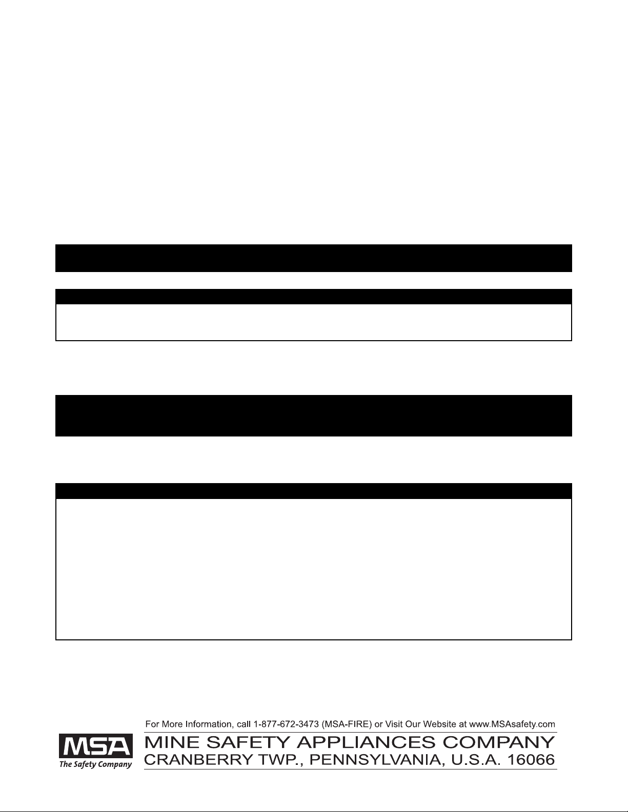
2. Use a fine-tip ink marker
and a ruler or straight
edge to draw a line on
the male coupling. Make
sure the line extends
across the joint and cou-
pling hex flats onto the
Audi-Larm or Quick-Fill
manifold body.
3. Put the dust cover on the coupling.
4. rasp the dust cover by hand and, using maximum effort,
attempt to loosen the coupling at the joint by turning the
dust cover counterclockwise. Do not use tools.
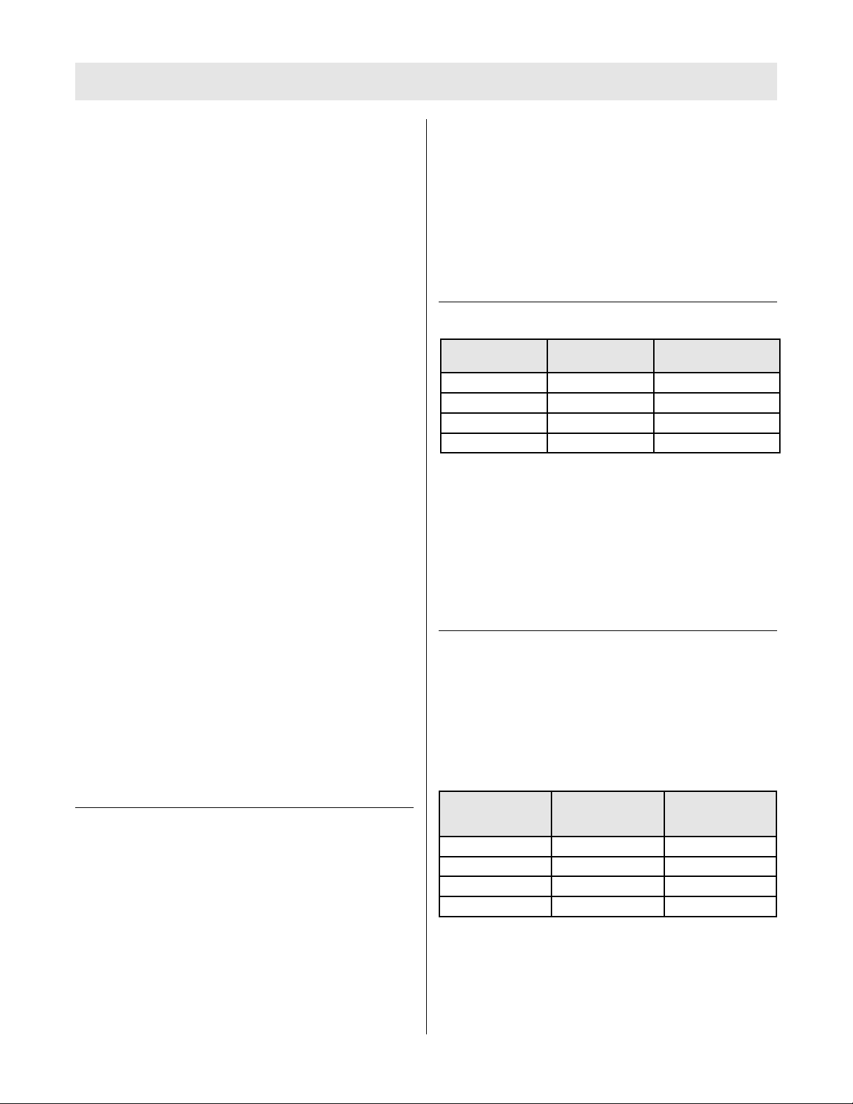
5. If the line does not line up
across the joint...
...or across the joint where
the coupling attaches to
the air mask, remove the
air mask from service until
a replacement coupling is
installed. If the line does
line up, the coupling is
sufficiently tight and the
air mask may be returned
to service.
10
MSA2211 (L) Rev. 8 - 10128861
"!
WARN NG

DONN NG
DONN NG THE A R MASK
1. Remove the facepiece from the case.
DO NOT use a cover lens in a high-temperature environ-
ment, such as firefighting. High temperatures may distort
the cover lens. Or, moisture trapped between a cover lens
and the facepiece lens may condense and distort vision.
Always remove the cover lens before donning the facepiece.
Misuse can result in serious injury or death.
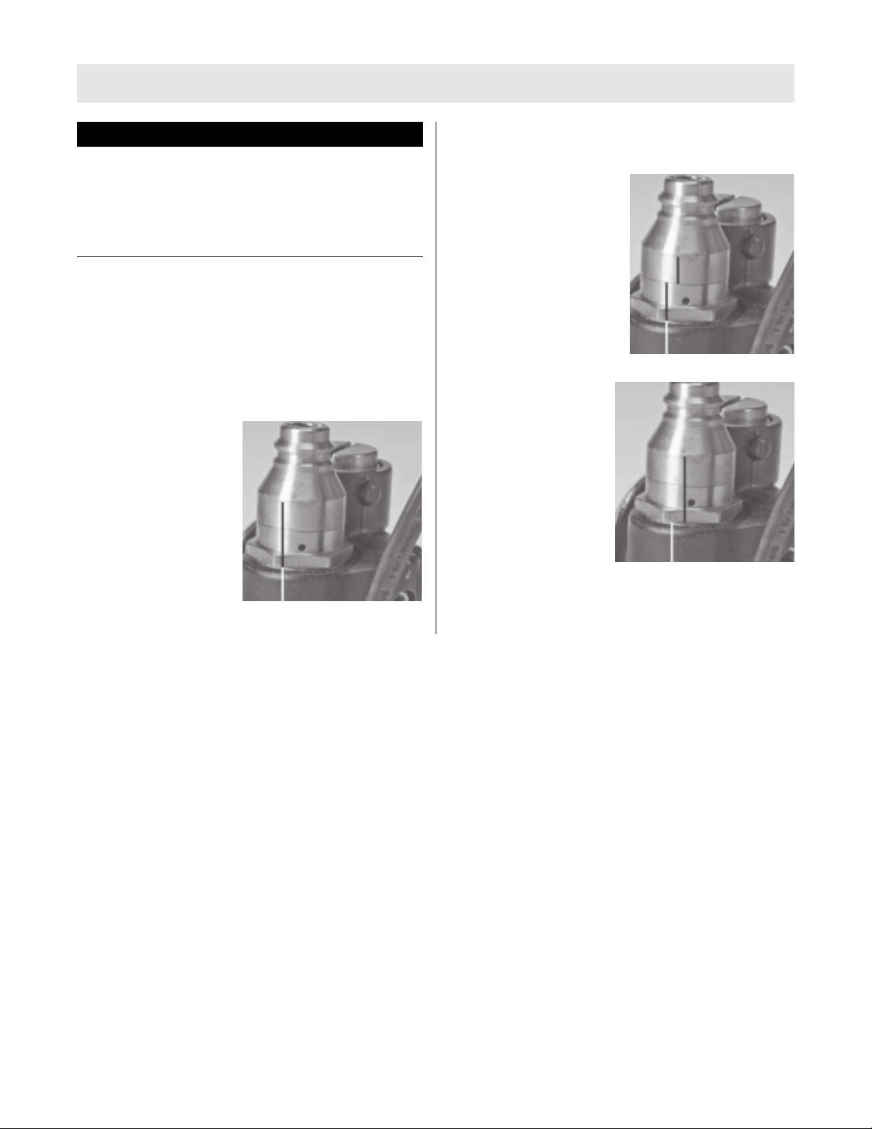
2. Ensure the the Audi-Larm
coupling nut is hand-tight
(no tools).
3. Ensure that the cylinder is fully pressurized.
4. Reach the right arm inside the right shoulder straps and
grasp the FireHawk M7XT Control Module. Slide the left arm
through the left shoulder straps.
5. Bend forward slightly; resting the carrier on the back.
6. Attach the chest strap buckle (optional).
7. Fasten the waist belt and pull it tight for a snug fit. Most of
the air mask weight should be carried on the hips.
8. Stand up straight. Pull the shoulder strap pull tabs out to
tighten the shoulder straps. Additional adjustments to the
waist belt may be needed.
9. The shoulder straps and waist strap ends must be tucked in
and lay flat across the body.
BEFORE US NG THE A R MASK
1. rasp the Firehawk Regulator and push the side buttons.
2. Ensure that the red bypass
knob is fully closed (clock-
wise).
3. Reach behind and fully
open the cylinder valve.
4. As the system pressure rises from 50 to 250 psi, both visible
and audible alerts activate automatically, indicating that the
air mask is functioning properly. Such alerts include a brief
ring from the Audi-Larm Alarm, a chirp from the FireHawk
M7XT Power Module, and a pressure display on the FireHawk
M7 HUD or I-HUD LEDs.
5. No air should flow from
the Firehawk Regulator. If
it does, repeat steps 1 and
2.
6. Ensure the FireHawk M7 HUD or I-HUD and FireHawk M7XT
pressure indicators show a full cylinder.
11 MSA2211 (L) Rev. 8 - 10128861
"!
CAUT ON
"!
WARN NG
"!
WARN NG
"!
WARN NG
Listen for any hiss or pop sounds from the Audi-Larm Alarm,
if heard, do not use the air mask. Return it to an MSA trained
or certified repairperson. Misuse can result in serious injury
or death.
DO NOT use the air mask if the Audi-Larm Alarm fails to ring,
the FireHawk M7XT Power Module fails to sound, or the
FireHawk M7 HUD or -HUD fails to light, The air mask must
be checked and corrected for proper operation by an MSA
trained or certified repairperson before using. Misuse can
result in serious injury or death.
DO NOT use the air mask if the cylinder gauge and FireHawk
M7 pressure readings are not within 5% (110/2216 psi and
225/4500 psi) of full cylinder pressure. Send the unit to an
MSA certified repair person.
DONN NG
7. Check the Firehawk
Regulator’s bypass
operation. rasp the red
knob and turn it counter-
clockwise. Listen for air-
flow and then turn it to
the off position.
8. Fully close the cylinder valve.
9. Listen for air leaks and watch the pressure indicators on the
FireHawk M7XT Control Module or NightFighter HUD
Transmitter for 10 seconds.
DO NOT use the air mask if the pressure drops more than
100 psi in ten seconds, The air mask must be repaired; other
wise, reduced available service time may result.
10. Crack the Firehawk Regulator bypass valve slowly to bleed off
pressure until the FireHawk M7 HUD or I-HUD and FireHawk
M7 pressure indicators drop below:
o 785 psi-approximately (2216 psi system)
o 1600 psi-approximately (4500 psi system)
At these pressures the FireHawk M7 HUD or I-HUD should display
a flashing red LED, the Audi-Larm Alarm should ring continuous-
ly, and the alarm button on the FireHawk M7XT Control Module
and the buddy lights on the FireHawk M7XT Power Module
should be flashing red.
11. When the system pressure falls below 250 psi, turn the
FireHawk M7XT Control Module off by depressing the reset
button (yellow) two times within approximately one
second.
DO NOT use the air mask if the Audi-Larm Alarm fails to ring
or fails to continuously ring down to pressures of 250 psi, or
if the FireHawk M7XT Control Module or FireHawk M7 HUD
or -HUD fails to light properly. The air mask must be
checked and corrected for proper operation by an MSA
trained or certified repair-person before using. Misuse can
result in serious injury or death.
NOTE: The FireHawk M7 HUD or I-HUD will automatically turn
itself OFF approximately 60 seconds after the air mask has been
depressurized. A red LED will flash until the device turns off.
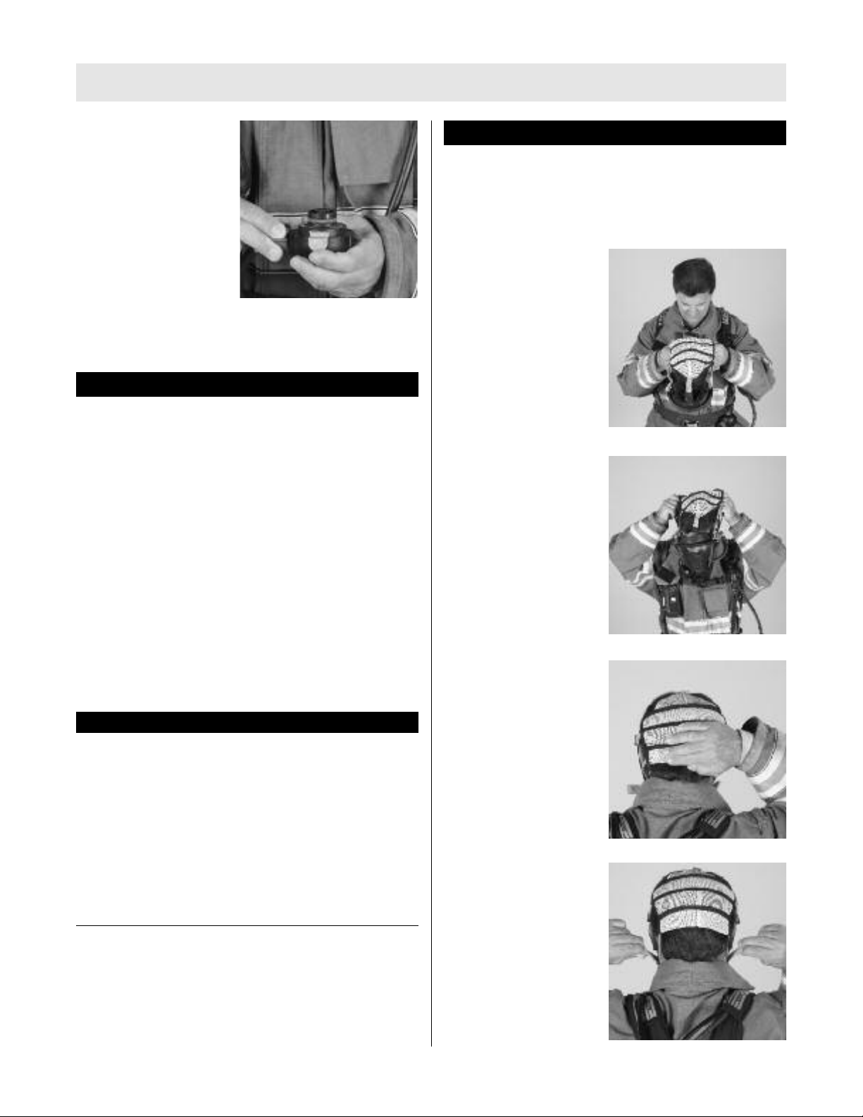
DONN NG THE FACEP ECE
NOTE: A nosecup is always required for use with this air mask.
A nosecup must be installed in the facepiece. Misuse can
result in serious injury or death.
NOTE: Before donning, ensure that the Firehawk Regulator seal-
ing ring is seated properly in its groove on the outlet of the regu-
lator and that it is not torn, gouged, or nicked.
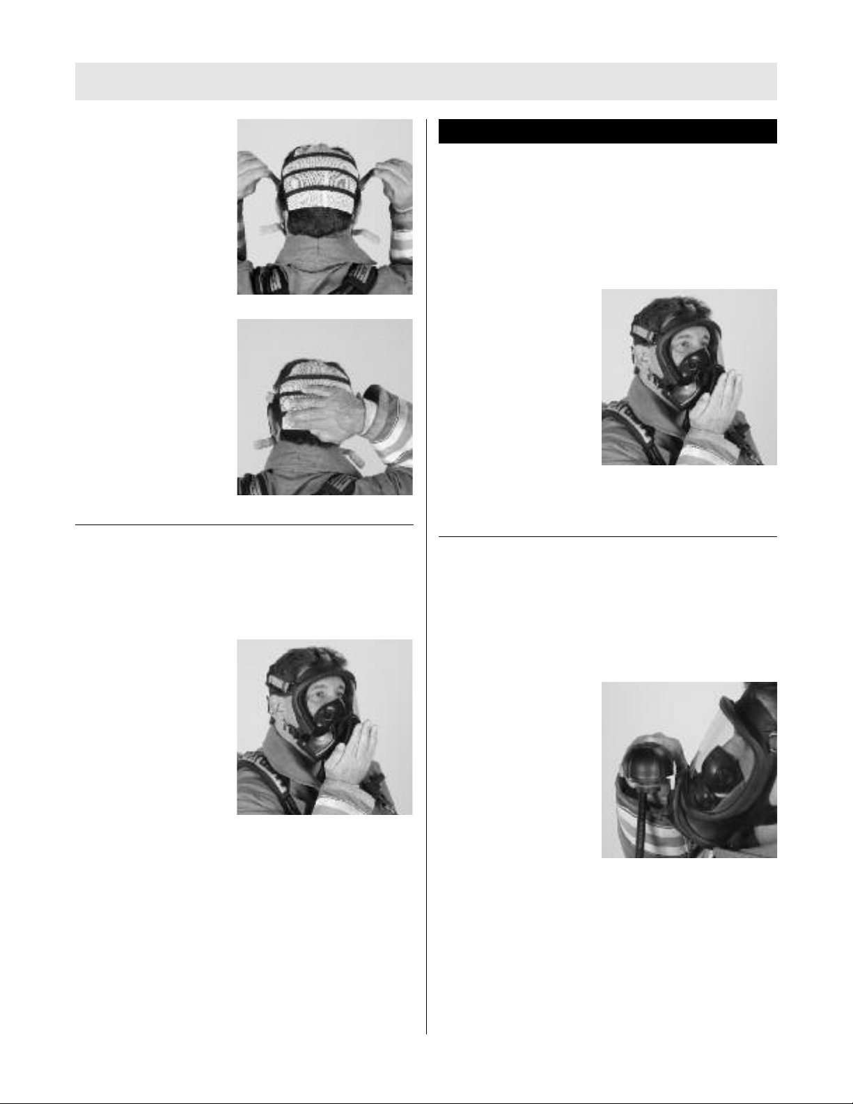
1. Loosen all the harness
straps. rip the bottom
straps.
2. Insert chin into the lower
part of facepiece, then
pull the harness back over
the head.
3. Pull the back of harness
downward until centered
at the back of the head.
4. Tighten the two lower
straps first by pulling
them straight back, not
out. Tighten the facepiece
until the mask is snug
against the face.
12
MSA2211 (L) Rev. 8 - 10128861
"!
CAUT ON
"!
WARN NG
"!
WARN NG
DONN NG
5. Tighten the two side tem-
ple straps in the same
manner as described in
step 4. Ensure that the
facepiece tabs are not
tucked under the face
seal.
6. Ensure the back of the
harness is centered on the
back of the head and that
the facepiece seal pro-
vides uniform pressure on
the face at all points.
Readjust the straps if
needed.
FACEP ECE F T CHECK
NOTE: Check the inhalation valve by inhaling. If the facepiece
does not provide sufficient flow of air, do not use facepiece. The
facepiece must be repaired or replaced.
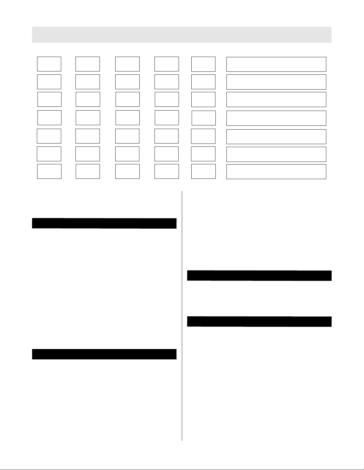
1. Check facepiece fit,
a. Hold the palm of the
hand over the face-
piece inlet adapter.
b. Take a deep breath and
hold it for at least 10
seconds. The facepiece
should collapse and
stay collapsed against
the face. If it does not,
readjust the facepiece
and test again. f this
does not correct the leak, do not use the facepiece.
2. Test the exhalation valve.
a. Take a deep breath and hold it.
b. Block the facepiece inlet adapter with the palm of the
hand and exhale. If the exhalation valve is stuck, a heavy
rush of air around the facepiece may be noticed. A sharp
exhalation of air may be needed to open the valve. If this
does not release the valve, do not use the facepiece.
This device may not seal properly to the face if a beard,
gross sideburns or similar physical characteristics (see NFPA-
1500 and ANS Z88.2) exist. An improper facial seal may
allow contaminants to leak into the facepiece, reducing or
eliminating respiratory protection. Do not use this device if
such conditions exist. The face-to-facepiece seal must be
tested before each use. Never remove the facepiece except
in a safe, non hazardous non-toxic atmosphere. Misuse can
result in serious injury or death.
3. Open the cylinder valve
fully. Push in on the side
buttons of the Firehawk
Regulator to stop air flow.
4. Listen for any hissing or popping sounds from the Audi-Larm
Alarm. If heard, return the air mask to an MSA trained or certi-
fied repairperson.
NSTALL NG THE SL DE-TO-CONNECT F REHAWK
REGULATOR ON THE FACEP ECE
NOTE: The slide-to-connect regulator has a side button with a
two pronged fork protruding from it. If this “fork” is not present
refer to the nstalling the Push-To-Connect Firehawk
Regulator section of this manual.
1. rasp and orient the regu-
lator so that red bypass
knob is pointing to the
right and slide button is
on top.
13 MSA2211 (L) Rev. 8 - 10128861
"!
WARN NG

DONN NG
2. Slide the regulator on to
the rail of the facepiece
cover. Slide the regulator
down the rail until the
regulator stops.
3. Insert the regulator into
the facepiece inlet by
pushing inward.
4. Ensure proper engagement by pulling on the regulator to
verify that the regulator is securely attached to facepiece.
DO NOT use the air mask unless the Firehawk Regulator is
connected properly. A regulator that is not installed correct-
ly can separate from the facepiece unexpectedly. Return the
air mask to an MSA trained or certified repairperson to cor-
rect the condition. Misuse can result in serious injury or
death.
5. Inhale sharply to start the airflow.
a. Check the bypass again by turning the red knob counter-
clockwise until increased airflow is felt. Close the bypass.
There must be a continuous flow of air when the bypass
knob is opened. f not, do not use the air mask. The air mask
must be checked and the condition corrected by an MSA
trained or certified repairperson before it can be used.
Misuse can result in serious injury or death.
NOTE: If the air mask passes all tests, it is ready for use. These
tests must be performed every time before entering a hazardous
atmosphere. If the air mask fails to meet any of the tests, the con-
dition(s) must be corrected before using the air mask.
NSTALL NG THE PUSH-TO-CONNECT F REHAWK
REGULATOR
NOTE: There are two versions (slide-to-connect and push-to-con-
nect) of the Firehawk Regulator available for the FireHawk M7XT
Air Mask. A slide-to-connect Firehawk Regulator can be identified
by examining the side buttons. The slide-to-connect has a side
button with a two pronged fork protruding from it. If this “fork” is
present, refer to Installing the Slide-To-Connect Firehawk
Regulator section.
1. rasp the Firehawk Regulator and insert the regulator into
the facepiece by pushing inward. Check proper engagement
by pulling on the regulator to ensure that the regulator is
securely attached to facepiece.
DO NOT use the air mask unless the regulator is connected
properly. A regulator that is not installed correctly can sepa-
rate from the facepiece unexpectedly. Return the air mask to
an MSA trained or certified repairperson to correct the condi
tion. Misuse can result in serious injury or death.
2. Inhale sharply to start the airflow.
3. Check the bypass again by turning the red knob counter-
clockwise until increased air flow is felt. Close the bypass.
There must be a continuous flow of air when the bypass
knob is opened. f not, do not use the air mask. The air mask
must be checked and the condition corrected by an MSA
trained or certified repairperson before it can be used.
Misuse can result in serious injury or death.
NOTE: If the air mask passes all tests, it is ready for use. These
tests must be performed every time before entering a hazardous
atmosphere. If the air mask fails to meet any of the tests, the con-
dition(s) must be corrected before using the air mask.
14
MSA2211 (L) Rev. 8 - 10128861
"!
WARN NG
"!
WARN NG
"!
WARN NG
"!
WARN NG

US NG THE A R MASK
PRECAUT ONS DUR NG USE
NOTE: If the breathing apparatus or any component fails, mal-
functions, or becomes damaged, contact MSA at 1-877-672-3473
(FIRE) or email customer service at [email protected]. SCBA
products may be considered hazardous material. In addition, U.S.
Department of Transportation exceptions and approvals may
apply to SCBA products. Please contact customer service at 1-
877-672-3473 (FIRE), or visit www.MSAnet.com/prism, for more
information.
Periodically check the pressure indicated on the FireHawk M7XT
chest mounted pressure indicator.
• Air flow in the air mask is reduced: Immediately open the
Firehawk Regulator bypass. Immediately return to fresh air.
• Air mask free-flows: Immediately return to fresh air.
• Audi-Larm Alarm Rings: Immediately return to fresh air.
• FireHawk M7 HUD or I-HUD low pressure indicator lights and
flashes red: Immediately return to fresh air.
• FireHawk M7XT Control Module alarm button flashes red:
Immediately return to fresh air.
Periodically check the pressure indicated on the FireHawk M7
HUD or I-HUD and FireHawk M7XT chest-mounted pressure indi-
cator during use. The FireHawk M7XT Control Module continually
displays the cylinder pressure while the FireHawk M7 HUD or I-
HUD indicates when each successive alert cylinder pressure level
(see Chart 1 for FireHawk M7 HUD or Chart 2 for I-HUD) of the
total cylinder pressure has been reached for 20 seconds. When
the needle on the FireHawk M7XT chest-mounted pressure indi-
cator reaches the red zone on the gauge face the Audi-Larm
Alarm will begin ringing, the FireHawk M7 HUD or I-HUD will dis-
play a flashing red LED, and the alarm button on the FireHawk
M7XT Control Module and buddy lights on the FireHawk M7XT
Power Module will flash red. When the Audi-Larm Alarm starts
ringing or when the pressure reaches approximately 33% of the
rated service pressure, return to fresh air.
The FireHawk M7 HUD or I-HUD, FireHawk M7XT Control Module,
and Audi-Larm Alarm indicate when cylinder pressure drops
below these approximate values:
o 785 psi-approximately (2216 psi system)
o 1600 psi-approximately (4500 psi system)
When the FireHawk M7 HUD or I-HUD, FireHawk M7XT Control
Module, or Audi-Larm Alarm indicates 33% cylinder pressure,
immediately return to fresh air.
NOTE: Air mask available service time is greatly reduced when
the Firehawk Regulator bypass is used.
Leave the contaminated area immediately if:
• Breathing becomes difficult
• Dizziness or other distress occurs
• You taste or smell the contaminant
• You experience nose or throat irritation
• SCBA not functioning according to the
instructions or training
Misuse can result in serious injury or death.
NOTE: See NIOSH Approval Label, Inserted in the Users
Instructions for complete list of CAUTIONS and LIMITATIONS for
the respirator.
Misuse or abuse of the FireHawk M7 HUD or -HUD, the
FireHawk M7XT Control Module, FireHawk M7XT Power
Module, or the equipment to which they are attached, or
using this equipment in a manner or situation not intended
by the manufacturer, may result in damage to the equip-
ment or may result in personal injury or death to user or
persons dependent on the user or damage to the
equipment.
• Always inspect the FireHawk M7 HUD or -HUD,
FireHawk M7XT Control Module, and FireHawk M7XT
Power Module for damage before use. f damage is
found, immediately remove the device from service.
• DO NOT alter these components. Altering will void the
ntrinsic-Safety rating and may affect the ntrinsic-Safety
of the device.
F REHAWK M7 HUD OR -HUD
FireHawk M7 HUD or -HUD Functionality
1. The FireHawk M7 HUD or I-HUD allows the user to see the
cylinder pressure while the air mask is in use. The FireHawk
M7XT Control Module wirelessly communicates with the M7
HUD or I-HUD. Both the FireHawk M7 HUD and I-HUD dis-
play the cylinder pressure in one quarter cylinder increments,
by an LED pattern.
• As each quarter cylinder pressure has been reached, down
to 50%, a unique LED pattern will be displayed for approx-
imately 20 second before extinguishing. The display can
be refreshed by pressing and holding the mode button
(green) on the FireHawk M7XT Control Module for approx-
imately three seconds.
• Just before 33% of the rated service pressure has been
reached, a single flashing red LED will be displayed and
will continue to flash until the unit is turned off or the
cylinder has been refilled.
• The FireHawk M7 HUD or I-HUD must be within approxi-
mately 18 inches of the FireHawk M7XT Control Module to
properly receive the signal being transmitted.
2. Both the FireHawk M7 HUD and I-HUD have a buddy light
that flashes red when the air mask has reached 33% of the
rated service pressure. This buddy light is not visible to the
user while the air mask is in use.
3. When the user of the air mask remains motionless for
approximately 20 seconds, the PASS pre-alarm will begin to
sound. During this pre-alarm, the FireHawk M7 HUD or I-HUD
will display an orange LED, and this LED will extinguish when
full PASS alarm has been reached or the pre-alarm has been
reset.
15 MSA2211 (L) Rev. 8 - 10128861
"!
WARN NG
"!
WARN NG
"!
WARN NG

US NG THE A R MASK
4. When an evacuation command has been sent to the user (if
the optional FireHawk M7XT Telemetry Module is in use), the
FireHawk M7 HUD or I-HUD will display an alternating red
and orange LED until the evacuation has been confirmed.
5. The FireHawk M7 HUD or I-HUD has a photo sensor that
automatically adjusts the brightness of the LEDs based on
the intensity of the ambient light measured outside of the
facepiece.
6. The FireHawk M7 HUD or I-HUD indicates a low battery con-
dition in either the HUD or FireHawk M7XT Power Module by
a flashing yellow LED. A user can confirm the power module
low battery indicator by viewing the low battery indicator on
the control module display. If this condition exists, return to
fresh air, and replace the batteries immediately. See
Replacing Batteries in the FireHawk M7 HUD or I-HUD.
Refer to Chart 1 for a full description of all FireHawk M7 HUD LED
patterns.
Refer to Chart 2 for a full description of all FireHawk M7 I-HUD
LED patterns.
16
MSA2211 (L) Rev. 8 - 10128861
Chart 1: FireHawk M7 HUD LED Patterns for FireHawk M7XT Air Masks
Y Y
R
RO
O
Y
100% to 76%
Full Cylinder, 4 reen LED
20 Sec. Steadily ON
75% to 51%
3/4 Full Cylinder, 3 reen LED
20 Sec. Steadily ON
50% to 34%
1/2 Full Cylinder, 2 Yellow LED
30 Sec. Flashing ON/OFF
33% to 0%
1/4 Full Cylinder, 1 Red LED
Flashing Continuously
Yellow LED, Low Battery HUD
and/or HUD Transmitter
Flashing Continuously
Orange LED for PASS Pre-Alarm
(integrated PASS)
Red / Orange LEDs alternating for
Evacuation Signal
(telemetry)
US NG THE A R MASK
17 MSA2211 (L) Rev. 8 - 10128861
REPLAC NG THE BATTER ES
Replacing the Batteries in the FireHawk M7 HUD
Replace the batteries in the FireHawk M7 HUD or -HUD
when the low battery LED flashes. Use only recommended
battery types. Change the batteries in a non-hazardous area
only. Misuse can result in serious personal injury or death.
1. Unthread the battery cap (counter-clockwise) on the
FireHawk M7 HUD battery tube.
2. Remove the battery cartridge from the FireHawk M7 HUD.
3. Remove the batteries and discard.
4. Ensure that moisture or debris is not present in the battery
compartment.
5. Inspect the battery cartridge for signs of damage such as cor-
rosion on the battery terminals or cracks in the cartridge. If
the battery cartridge is damaged, replace the cartridge
immediately.
6. Insert three AAA alkaline batteries in the appropriate loca-
tions on the cartridge. Follow the notations on the cartridge
to ensure proper battery orientation.
Use only Rayovac 824 LR03, Rayovac Ultrapro LR03,
Energizer E92, Energizer ndustrial EN92, Duracell MN2400,
or Duracell Procell PC2400 alkaline batteries in the FireHawk
M7 HUD. Use of other batteries, or a combination of batter-
ies from different manufacturers, will affect the performance
of unit and void the ntrinsic Safety Approval.
7. Insert the battery cartridge into the battery tube on the
FireHawk M7 HUD.
8. Before installing the battery cap, verify that the o-ring is in
place and free of damage and debris. If the o-ring is missing or
damaged, replace o-ring. Failure to do so may allow moisture
or contaminants into the battery tube and cause the device to
not function properly.
9. Thread the battery cap on to the battery tube of the
FireHawk M7 HUD (clockwise). Hand-tighten cap until snug.
Do not over-tighten battery cap.
10. As the battery cap makes contact with the battery cartridge,
verify that the FireHawk M7 HUD display turns on and goes
through its start up sequence before turning off. The yellow
LED should not be flashing.
Replacing the Battery in the FireHawk M7 -HUD
Replace the batteries in the FireHawk M7 HUD or -HUD
when the low battery LED flashes. Use only recommended
battery types. Change the batteries in a non-hazardous area
only. Misuse can result in serious personal injury or death.
DO NOT attempt to remove the -HUD by pulling on one
side or the other as this may cause damage to the device.
Use only even force on both sides of the device. Misuse can
result in serious personal injury or death.
1. Unthread the battery cap (counter-clockwise).
2. Remove the battery and discard.
3. Ensure that moisture or debris is not present in the battery
compartment.
4. Inspect the battery cap for signs of damage such as corro-
sion on the battery terminal or cracks in the cap. Replace the
battery cap if it is damaged.
5. Insert a replacement battery.
Chart 2: FireHawk -HUD LED Patterns for FireHawk M7XT Air Masks
"!
WARN NG
"!
WARN NG
"!
WARN NG
"!
WARN NG
Y
R
Y
O
R O
76% to 100%
Full Cylinder, 3 reen Right Side LED
75% to 51%
3/4 Full Cylinder, 2 reen Right Side LED
34% to 50%
1/2 Full Cylinder, 2 Yellow Right Side LED
Flashing Continuously
33% to 0%
1/4 Full Cylinder, 1 Red Right Side LED
Flashing Continuously
Low Battery
Left Side Yellow LED
Flashing Continuously
PASS Pre-Alarm
Orange Left Side LED
Evacuate
Red and Orange Left Side LED
Flashing Alternating
Y

US NG THE A R MASK
Use only Duracell Ultra M3, Panasonic Photopower CR2 or
Energizer CR2 Photo lithium batteries in the FireHawk M7
-HUD. Use of other batteries will affect the performance of
the unit and void the ntrinsic Safety Approval. Misuse can
result in serious personal injury or death.
6. Before installing the battery cap, verify that the o-ring is in
place and free of damage and debris. If the o-ring is missing
or damaged, replace the o-ring.
Failure to repla e a missing or damaged o-ring may allow
moisture or ontaminants into the housing and ause the
devi e to not fun tion properly.
7. Thread the battery cap into the housing and tighten until the
index mark on the battery cap aligns with the index mark on
the housing. Do not over-tighten the battery cap.
DO NOT over-tighten the battery cap. Over-tightening the
battery cap can result in a cracked housing and a com-
promised water seal. Misuse can result in serious personal
injury or death.
8. Verify that the FireHawk M7 I-HUD display turns on and goes
through its start-up sequence before turning off.
BATTERY D SPOSAL/RECYCL NG
Dispose of or recycle batteries in accordance with all applicable
federal, state, and local regulations.
DO NOT dispose of the batteries in fire. They may explode.
Misuse can result in serious personal injury or death.
ASSEMBLY OF THE F REHAWK M7 HUD ON THE FACEP ECE
NOTE: Assemble the FireHawk M7 HUD to the facepiece bracket
before donning the air mask.
With the facepiece lying on its side:
1. Align the metal tab on the FireHawk M7 HUD with the metal
plate on the front edge of the bracket.
2. Rotate the FireHawk M7 HUD so that the tab falls into the
slot behind the thumbscrew.
3. Thread the thumbscrew into the tab to finger-tight.
ASSEMBLY OF THE F REHAWK M7 -HUD N THE FACEP ECE
1. Install the I-HUD by pushing forward on the center nose-
bridge.
NOTE: The locking mechanism (top arm of the retaining clip) will
wrap around the IHUD’s nose-bridge from the backside.
2. Push forward on the arm of the clip to ensure there is little to
no space between the bend of the locking arm and the
nose-bridge of the I-HUD.
NOTE: To remove the I-HUD, pull the locking arm away from
the nose bridge of the I-HUD. Pull the arm back and away on
an angle. The locking arm is constructed of spring steel , allow-
ing the arm to spring back into the proper position for the
next I-HUD insertion.
DO NOT attempt to remove the -HUD by pulling on one
side or the other as this may cause damage to the device.
Use only even force on both sides of the device. Misuse can
result in serious personal injury or death.
FUNCT ONAL TESTS
NOTE: Refer to the Visual Inspection and Functional Test
section of this manual.
Always test the FireHawk M7 HUD or -HUD and the entire
air mask to be sure that the system operates properly before
entering any hazardous atmosphere. DO NOT use this
device unless it passes all inspection and functional tests.
Misuse can result in serious personal injury or death.
18
MSA2211 (L) Rev. 8 - 10128861
"!
WARN NG
"!
WARN NG
"!
WARN NG
"!
WARN NG
"!
WARN NG
"
WARN NG
"!
CAUT ON
DO NOT use a screwdriver to tighten the thumbscrew.

US NG THE A R MASK
19 MSA2211 (L) Rev. 8 - 10128861
*Action only available when the FireHawk M7XT Telemetry Module is used.
**Action available only if SCBA with integrated PASS is configured with Thermal Alarm option.
Chart 3: Audible / Visual ndicators Firehawk M7XT Power Module and Control Module
ACT ON AUD BLE ND CATOR,
POWER MODULE
V S BLE ND CATOR,
CONTROL MODULE
automatic activation with
the system pressurized
single upsweep with ending
lower tone green / red LED flash front panel
the manual activation
alert sequence of 1 down
sweep, 4 upsweeps (medium
speed), 8 upsweeps (high
speed), and repeated until
deactivated.
green / red LED flash front panel - red light
flashing
sensing mode (with or without
pressure) none green LED flashes
pre-alarm
with or
without
pressure
2 low speed low / high / low tones
red LED flashes
4 medium speed low / high / low
tones
4 stages of 7 rapidly alternating
low / high tones
full alarm (with or without
pressure)
alert sequence of 1 down
sweep, 4 upsweeps (medium
speed), 8 upsweeps (high
speed), and repeated until
deactivated.
red LED flashes
Deactivation of full alarm
( 2 reset button presses) single short (high) tone beep
red LED flashes
green LED flashes
deactivation of pre-alarm
(with shake or move unit) none green LED flashes
redundant alarm (cylinder
pressure is below 33% of rated
service pressure)
none red LED flashes
low battery 1 beep every 5 seconds empty battery icon on display
thermal alarm activation** (see
thermal alarm activation curve) 1 beep every 3 seconds** flashing thermometer icon on display**
radio link
with
base
station*
none radio link indicator icon in upper left corner
of display*
none radio link indicator icon disappears*
evacuation signal received*
continuous medium speed
upsweep alerts until
acknowledged*
flashing “running man” icon appears on
display*
first 4 seconds
(approx)
link is
established
out of range
second 4 seconds
(approx)
last 4 seconds
(approx)

US NG THE A R MASK
FUNCT ONAL TESTS
NOTE: Refer to the Visual Inspection and Functional Test section
of this manual.
Always test the FireHawk M7 HUD or I-HUD and the entire air
mask to be sure that the system operates properly before enter-
ing any hazardous atmosphere. DO NOT use this device unless it
passes all inspection and functional tests. Failure to follow this
warning can result in serious personal injury or death.
F REHAWK M7XT CONTROL MODULE FUNCT ONAL TY
• The FireHawk M7XT Control Module is assembled to the
gauge line hose and is connected to the FireHawk M7XT
Power Module by the power cable. The FireHawk M7XT
Control Module serves as the user interface with the air mask
and it also serves as the wireless transmitter for the FireHawk
M7 HUD or I-HUD.
• The FireHawk M7XT Control Module has three control but-
tons.
o The RESET/OFF button (yellow) on the side of the FireHawk
M7XT Control Module resets the PASS device from the full
alarm mode. It also shuts the unit off after the cylinder valve
has been closed and all pressure is bled from the system.
When the optional FireHawk M7XT Telemetry Module is
used, the Reset button allows the user to confirm an evacua-
tion command.
o The center lighted ALARM button (green/red) activates the
full PASS alarm with or without air pressure.
o The top MODE button (green) will refresh the display in
the FireHawk M7 HUD or I-HUD, activate the backlight on
the display of the FireHawk M7XT Control Module, set the
FireHawk M7 HUD or I-HUD to continuous display mode,
and toggle the FireHawk M7XT Control Module digital dis-
play mode between pressure remaining and calculated
service time remaining. When the FireHawk M7XT Control
Module is OFF, the mode button (green) can be used to
scan an ID Tag into the unit (when optional FireHawk
M7XT Telemetry Module is used).
• The FireHawk M7XT Control Module turns on automatically
when the user opens the air mask cylinder valve. As the sys-
tem pressure reaches approximately 250 psi, both visible and
audible alarms activate automatically, indicating that the unit
is functional (audible alarms are emitted from the FireHawk
M7XT Power Module located on the backplate). The unit
remains in monitor mode until the user closes the cylinder
valve, purges the system pressure, and presses the reset but-
ton (yellow) on the side of the FireHawk M7XT Control
Module two times within approximately one second.
• While the air mask is in use, if the user is motionless for
approximately 20 seconds, the PASS (FireHawk M7XT Control
Module and FireHawk M7XT Power Module) enters pre-alarm
with audible and visual alerts as indicated in Chart 1 (FireHawk
M7 HUD), Chart 2 (FireHawk M7 I-HUD), and Chart 3 (FireHawk
M7XT Power and Control Modules). Movement of the FireHawk
M7XT Control Module cancels the PASS pre-alarm.
• If the user remains motionless for 30 seconds (approximate-
ly), the PASS enters full alarm.
• The PASS can be set into full alarm at any time (even without
air pressure) by pressing and holding the alarm button on
the FireHawk M7XT Control Module.
• The PASS function uses red and green LEDs behind the alarm
button of the FireHawk M7XT Control Module and buddy
lights on the FireHawk M7XT Power Module to display its sta-
tus visually:
o reen LEDs start to flash when the cylinder valve is
opened and shows that the device is operational.
o Red LEDs flash slowly when the device is in PASS pre-
alarm and flash rapidly when the device is in full PASS
alarm.
o Red LEDs flash when the cylinder pressure is at or below
33% of the rated service pressure.
• The four C alkaline batteries in the FireHawk M7XT Power
Module supply the FireHawk M7XT Control Module with
power. The system notifies the user when the batteries need
to be replaced by emitting an audible beep (1 beep every 5
seconds) from the FireHawk M7XT Power Module, displaying
and empty battery icon on the display of the FireHawk M7XT
Control Module, and by a double flashing yellow LED on the
FireHawk M7 HUD or I-HUD.
• The FireHawk M7XT Control Module has a data logging fea-
ture that records information about the air mask while the
FireHawk M7XT Control Module is turned on. This data log
memory can be accessed using the FireHawk M7 Reader /
Tag Writer Interface Module.
• The FireHawk M7 Reader / Tag Writer Interface Module con-
tains an internal real time clock. This clock can be reset using
the FireHawk M7XT Control Module. By default, the internal
clock is set to Eastern Standard Time.
Before placing the FireHawk M7XT Air Mask in service, verify
that the internal clock is set to the appropriate time as per
the user’s geographic location. Failure to do so can result in
inaccurate data logging of the FireHawk M7XT Control
Module.
The time may be viewed or changed using the FireHawk M7
Reader / Tag Writer Interface Module. For additional instructions
on using the FireHawk M7 Reader / Tag Writer Interface Module
refer to the interface module instructions (P/N 10088977).
20
MSA2211 (L) Rev. 8 - 10128861
"!
WARN NG
Table of contents
Languages:
Popular Respiratory Product manuals by other brands

Dräger
Dräger PAS Colt Series Instructions for use

Sundstrom
Sundstrom SR 520 Instructions for use

MSA
MSA Safe Escape NIOSH CBRN 15 Operation and instructions

Cerva
Cerva 10217 quick start guide

Ultimate Industrial
Ultimate Industrial UCFX3-P2V Fitting instructions

ResMed
ResMed Flow Generator S8 Elite System Illustration manual


