Steril-Aire ESE 1 Series User manual

Installation and Operation Instructions
NOTE: Read this entire instruction sheet before starting the installation.
IMPORTANT CONSIDERATIONS
Improper installation, adjustment, alteration, service,
maintenance, or use can cause fire, electrical shock, or
other conditions which may cause personal injury or
property damage. Consult your supplier or Steril-Aire for
information or assistance.
Understand the signal words DANGER, WARNING, or
CAUTION. These words are universally used for overall
safety. DANGER identifies the most serious hazards
which will result in severe personal injury or death.
WARNING signifies hazards which could result in
personal injury or death. CAUTION is used to identify
unsafe practices resulting in minor personal injury or
product and property damage.
WARNING: Before performing maintenance or
service on fixture, ensure unit is unplugged.
Electrical shock can cause injury or death.
CAUTIONS:
•Never expose eyes or skin to UVC light.
Wear gloves, face shield/glasses (per ANSI
Z87.1) and cover all exposed skin.
•Do not touch EmitterTM glass without gloves.
Damage to Emitter may result. Oil from
fingerprints will permanently etch glass of
Emitter and weaken structure. If necessary,
clean Emitter using a Steril-Aire cleaning kit,
isopropyl alcohol and a lint-free wipe may be
substituted.
•UVC Emitters are fragile. To prevent
accidental breakage, handle the UVC Emitter
with care.
•Voltages outside of the range designed for
the unit will void the warranty and do
permanent damage to the entire unit.
•Emitter contains a small quantity of mercury.
If an Emitter breaks, clean and dispose with
the same care as a fluorescent lamp.
•UVC energy may cause damage to non-
metallic components. Such components
shall be protected with UV resistant material
such as aluminum foil, aluminum duct tape,
metallic shields, etc.
•The qualified installer or agency must use
factory kits and accessories when installing
this product.
Once the installation is complete, the UVC fixture
should be operated continuously to preclude the
development of mold and bacteria. It is not
recommended to cycle the Emitters by time clock or
fan operation.
ESE 1 SERIES
ENHANCED SINGLE ENDED
FIXTURE, 24” – 61” EGTS
120-277 V
Part Number 11003000
Patents 6,297,924/ 6,280,686/ 6,313,470/ 6,372,186/ 6,423,882/ 6,500,267/ 6,589,476/
6,627,000/ 6,783,578/ 7,140,749/7,282,728/ 7,459,694 & others pending
Made in the USA
INSTALLATION &OPERATION
NOTE: ENSURE THAT EMITTER IS INSTALLED BEFORE
POWER IS APPLIED. INSTALLING EMITTER AFTER
POWER HAS BEEN APPLIED MAY TRIGGER THE “END-
OF-LAMP-LIFE CIRCUIT” AND THE EMITTER MAY FAIL
TO LIGHT. IF THIS HAPPENS, SHUT OFF POWER FOR 10
SECONDS AND THEN TURN POWER BACK ON. EMITTER
WILL THEN LIGHT.
1. Consult all applicable codes before installing.
Check fixture label(s) for the correct power
requirements and supply the correct voltage
from a suitable, protected (fused), and grounded
power source.
2. Air Handler should have signs (provided in
English and Spanish) in appropriate languages
alerting maintenance personnel to the possible
hazard of looking at or exposing skin to UVC
energy. Service accesses may be equipped with
a glass or Lexan® window to view Emitters;
viewports are available as an accessory. UVC
energy does not penetrate common glass or
Lexan®.
3. If applicable, remove outer cover of air handler.
4. UVC energy may damage some plastics. Wrap
suspect items with aluminum tape; use metallic
conduit or use other appropriate shielding where
these items may be in "line of sight" of the UVC
energy.
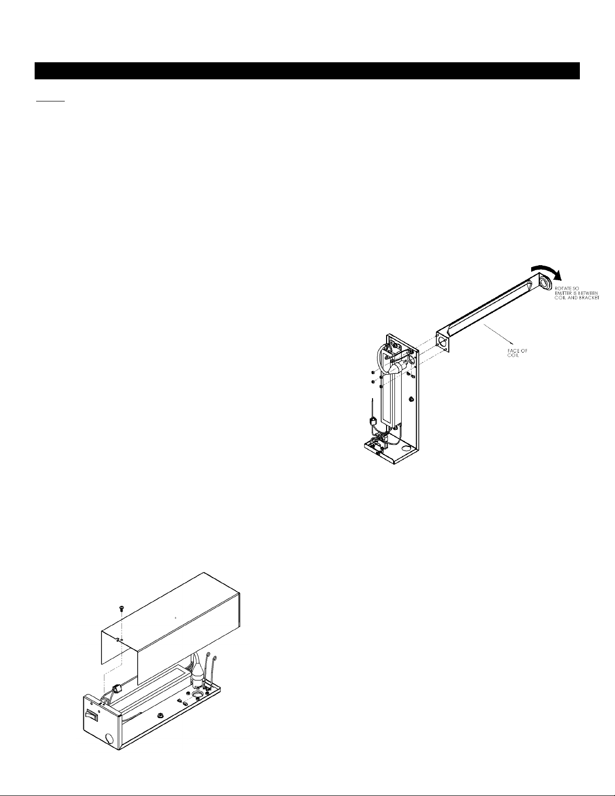
5. The Emitter shall be installed downstream from
the cooling coil and above the drain pan. To
achieve equal distribution of UVC intensity on
the face of the coil, the Emitters shall be
positioned from the face of the coil at a distance
equal to half the vertical height that the light is
covering.
6. The Emitter shall also:
oBe at least 1” away from any heating coil.
oNot make contact with the air handler
blower.
7. If applicable, replace the outer cover of air
handler.
8. Remove cover to ESE Fixture.
9. Using the fixture base as a template scribe and
then create an insertion hole, 2” diameter where
you want the emitter to be located.
CAUTION: Do not drill into coil, refrigerant lines
or other mechanical equipment.
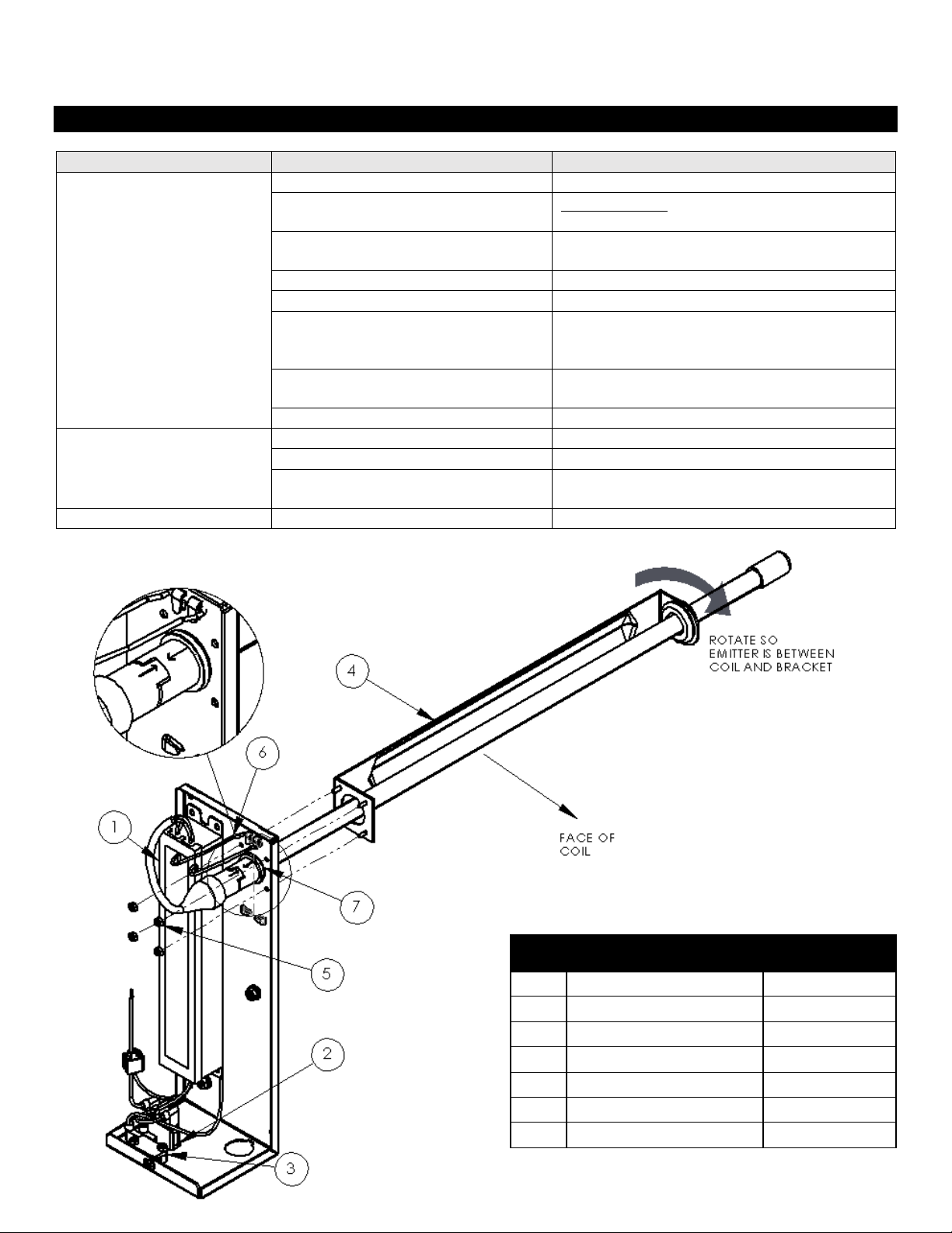
10. Install support bracket (item 4) using the 4 nuts
4-40 provided (item 5). Align the face of the
support bracket so that it faces the coiling coil on
final installation. The bracket can be rotated 360
degrees at 90 degrees intervals.
11. Drill suitable holes for each fastener (unless
using self-tapping screws). Using the proper #10
fastener for your application, install fixture(s) and
wire in accordance with the applicable code.
12. Install UVC Emitter. Secure with spring clip.
Ensure that there is an O-ring on the emitter.
Failure to install O-ring can possibly damage the
emitter base.
13. Complete all power connections and replace
cover to the fixture
14. Reconnect power to the air conditioner and
toggle the installed switch to the “On” position.
The Emitter should emit a bright blue hue,
indicating that it is properly powered.
15. Attach the Caution Label and Lamp Change
Date Label to air handler access panel so they
are clearly visible.
16. Emitters need to be periodically replaced to
maintain design output. Emitters should be
replaced after 9,000 hours of use.
TROUBLESHOOTING
Symptom
Possible Causes
Corrective Action
Emitter does not light
Cover Off/interlock switch open
Install cover/depress interlock switch
Momentary loss of power.
Reset Power Turn off power for 10
Seconds, and then turn power on.
Poor connection
Check connection to emitter. Check
wiring connections. Reset Power
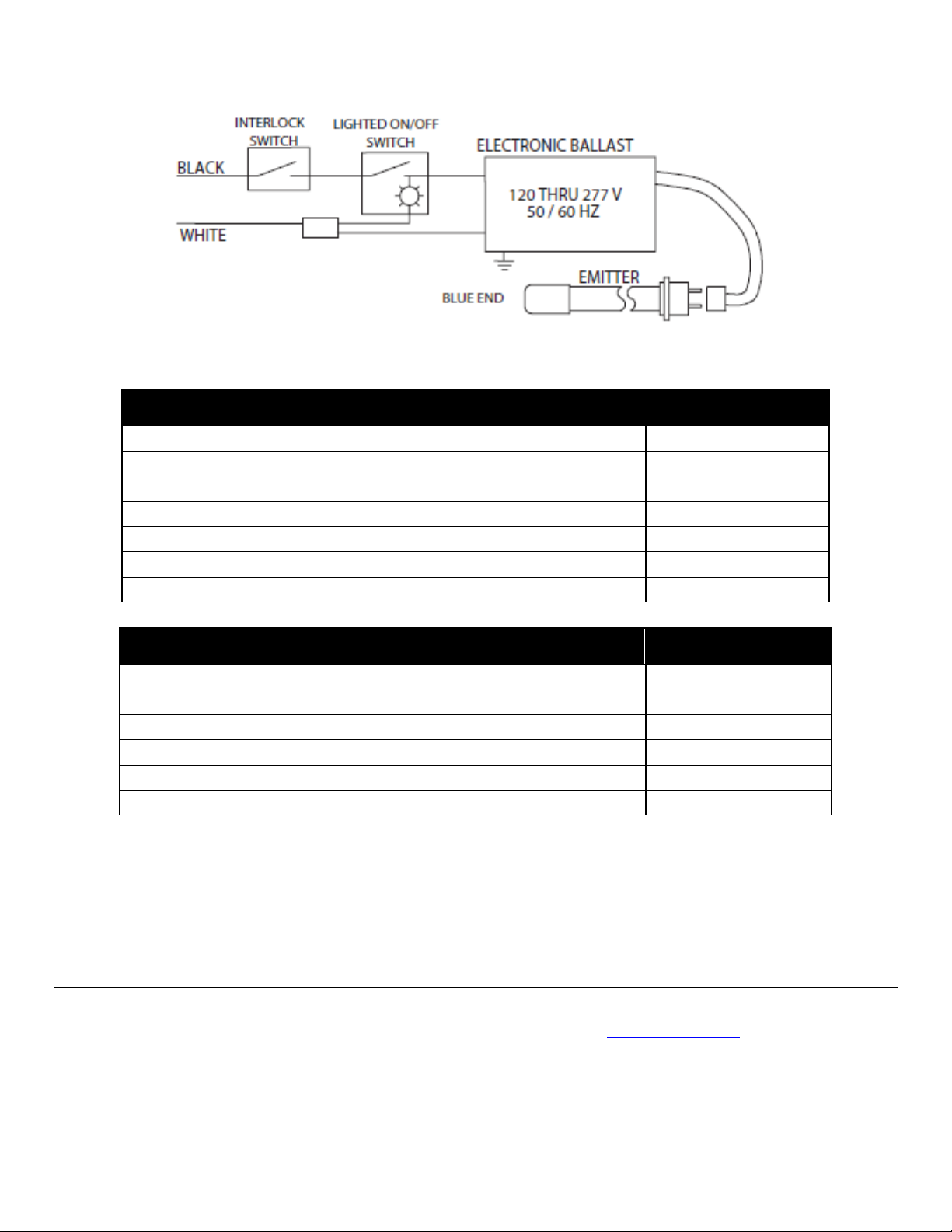
Incorrect wiring
Inspect circuit to wiring diagram.
Dirty pins
Clean pins. Reset Power
System malfunction
Check system components, interlock
door switches, relays, motion
detectors, etc.
Emitter reaching end of life
Replace with new Emitter. Reset
Power
Defective Power supply
Replace Power Supply.
Visibly Weak Emitter
Light
Bad Wiring
Check wiring to emitter
Emitter reaching end of life
Replace Emitter
Emitter too Cold
If emitter is at or below 35°F(1°C),
Emitter is too cold to operate properly.
Red/Orange Emitter
Emitter reaching end of life
Replace Emitter
ITEM
DESCRIPTION
PART NUMBER
1
Power Supply
10000189
2
Switch On/Off
11000112
3
Switch Interlock
11000113
4
Support Bracket
12000501
5
4-40 Nylon Insert Locknut
11000115
6
Spring
11000104
7
O-Ring
11000105
_________________________________________________________________________________________________
Thank you for choosing Steril-Aire, #1 “UVC for HVAC” solution provider worldwide. Please contact your local supplier or Steril-Aire
directly if we can provide any further information or service. Call 1-818-565-1128 or visit www.steril-aire.com. Your satisfaction is very
important to us.
The health aspects associated with the use of this product and its ability to aid in disinfection of environment air have not been
investigated by UL.
© 2017 Steril-Aire, Inc. All rights reserved. 1391
REPLACEMENT PARTS
PART NUMBER
EGTS 24 VO - Enhanced 24" Single Ended Emitter
21000310
EGTS 30 VO - Enhanced 30" Single Ended Emitter
21000410
EGTS 36 VO - Enhanced 36" Single Ended Emitter
21000510
EGTS 42 VO - Enhanced 42" Single Ended Emitter
21000610
EGTS 50 VO - Enhanced 50" Single Ended Emitter
21000910
EGTS 61 VO - Enhanced 61" Single Ended Emitter
21000810
ESE Replacement Power Supply 120-277 V
10000189
ACCESSORIES
PART NUMBER
Adjustable Leaver Interlock Switch
90000119
AHU Viewport for 2” wall/panel
90000217
AHU Viewport Assembly for up to 3” wall/panel
90000227
UVC Watch Dog 120V
80000200
UVC Watch Dog 230V
80000201
Cleaning Kit
90000100
This manual suits for next models
1
Other Steril-Aire Control System manuals


Popular Control System manuals by other brands


Yeti
Yeti SMARTBENCH quick start guide

Nederman
Nederman Fan Inverter Installation and service manual

HEIDENHAIN
HEIDENHAIN ITNC 530 - CONVERSATIONAL PROGRAMMING Service manual

CNC Design
CNC Design CNC GUITAR PICKUP QUAD COIL WINDER MK1 instructions

Siemens
Siemens Desigo TRA Mounting and installation manual

Panasonic
Panasonic CZ-RWST3 operating instructions