Firetrol FTA3100S Product manual

1
INSTALLATION AND MAINTENANCE GUIDE FOR
MARKIII+ VARIABLE SPEED ELECTRIC FIRE PUMP
CONTROLLERS
WITH TRANSFER SWITCH
MODEL SERIES: FTA3100S, FTA3130S

2
FTElectric Manual v2.8.9.x (CDL)
Variable speed electric fire pump controllers (FTA31xx) are designed to start an electric motor driven fire pump.
The FTA31xx is equipped with a Variable Frequency Drive (VFD) that will regulate the motor speed by controlling
the frequency outputted to the motor in order to reach a certain pressure (Setpoint pressure). It can either start the
fire pump manually through the local start pushbutton or automatically through the sensing of a pressure drop in
the sprinkler system. The fire pump controller is supplied with a pressure transducer. The fire pump can be
stopped manually with the local stop pushbutton or automatically after the expiration of a field programmable
timer. In both cases, stopping is only allowed if all starting causes have disappeared.
Types of Electric Fire Pump Controllers
FIRE PUMP CATALOG NUMBER
MODEL No. EXAMPLE: FTA3100S-AM100B-TSA
Model: FTA3100S = Variable Speed Electric Fire Pump Controller
Start Option: A = Automatic Start with Selectable Auto or Manual Stop
Short Circuit Current Rating: M = 100 kA
Rating: 100 = 100 HP
Voltage: B = 440 - 480V, 3 Phases, 60 Hz
TSA: Automatic Transfer Switch
Variable Speed Electric Fire Pump Controllers Mode Switch
The FTA31xx is equipped with a VFD Mode Switch that is located under the MarkIII+. It is protected by a
lockable cover, and has 2 positions, VFD and BYPASS. In normal usage the VFD Mode Switch should remain in
the VFD mode position.
VFD: The controller will start the motor using the VFD starting mean.
BYPASS: The controller will start the motor using the bypass starting mean.
Starting mean
VFD STARTING MEAN
The variable speed electric fire pump controller is equipped with a Variable Frequency Drive (VFD) which is the
primary starting mean. Upon reception of a starting demand, the motor will be started using the VFD. The VFD will
adjust the speed of the motor by varying the frequency outputted to the motor to maintain the system pressure at a
desired set pressure (Setpoint Pressure).
BYPASS STARTING MEAN
A secondary starting mean will take over the motor if the VFD comes to fail or if the VFD mode switch is placed in
the Bypass mode position.
MANUAL VFD BYPASS
If the mode switch change position while the motor is running, the motor will stop and restart in the new
mode.
AUTOMATIC VFD BYPASS
When running in VFD mode, the controller will automatically bypass the VFD following the activation of
one of the 3 VFD alarm: VFD FAULT, VFD UNDERPRESSURE or VFD NOT READY. Once the VFD has
perform an Automatic VFD Bypass, it will stay in that state until the alarms are manually reset.
Introduction

3
FULL VOLTAGE STARTER
MODEL FTA3100S: ACROSS-THE-LINE STARTER
This model will apply full voltage to the motor when the bypass starting mean is activated.
REDUCED VOLTAGE STARTERS
MODEL FTA3130S: SOLID STATE STARTER
This model does not require a multi-connection motor. It only requires 3 conductors between the
controllerand the motor.
Upon activation of the bypass starting mean, a solid-state starter is utilized to supply a step less ramp-up
voltage to the motor until the motor reaches its full speed. At that time, a fully horsepower rated by-pass
contactor is energized, connecting the motor directly to full voltage and eliminating all heat loss within the
solid-state starter. This controller also features a soft motor stopping mode and a hard stop mode. For a
hard stop, hold the stop pushbutton until the motor stop.
Methods of Starting/Stopping
The controllers are available as combination automatic / non-automatic with provision for manual or automatic
shutdown (an automatic shutdown is only possible after an automatic start).
METHODS OF STARTING
AUTOMATIC START
The controller will start automatically on low pressure detection by the pressure sensor when the pressure drops
below the cut-in threshold.
MANUAL START
The motor can be started by pressing the START push button, regardless of the system pressure.
REMOTE MANUAL START
The motor can be started from a remote location by momentarily closing a contact of a manual push button.
REMOTE AUTOMATIC START, DELUGE VALVE START
The motor can be started from a remote location by momentarily opening a contact connected to an automatic
device.
EMERGENCY START
The motor can be started manually by using the emergency handle. This handle can be maintained in a closed
position. The manual “EMERGENCY RUN” device will always initiate across-the-line starting.
Important: to avoid damaging the contactor, it is recommended to start the motor in this manner:
1) Shutdown the main power by using the main disconnect means,
2) Pull the emergency handle and lock it in closed position,
3) Turn the power back on by using the main disconnect means.
WEEKLY START
The engine can be started (and stopped) automatically at the preprogrammed time.
TEST START
The motor can be started manually by pressing the run test button.
*In VFD mode, if a start requests not based on the system pressure is triggered and the pressure remains above
the Setpoint pressure, the motor will run at the minimum speed (VFD parameter).
METHODS OF STOPPING
MANUAL STOP
Manual stop is done by pressing the priority STOP push button. Note that pressing the stop push button will
prevent the motor from restarting as long as the button is pressed, plus a two second delay.

4
AUTOMATIC STOP
Automatic stop is possible only after an automatic start and this function has been activated. When this function is
enabled, the motor is automatically stopped 10 minutes after the restoration of the pressure (above the cut-out
threshold) given that no other run cause is present.
EMERGENCY STOP
The emergency stop is always possible in any starting condition and is done by using the main disconnecting
means located on the door.
Transfer switch operation Sequence
TRANSFER TO ALTERNATE POWER SOURCE
The Transfer to Alternate Power Source starts automatically when at least one of the following conditions are
present:
- Normal Power voltage falls below 85% of nominal voltage,
- Normal Power Phase Reversal is detected,
- Transfer Switch Test push button is pressed.
When an under voltage condition on any phase of the Normal Power source is detected by the sensor, a 3 second
normal power source outage delay timer starts timing.
If the normal source voltage rises above the sensor dropout setting before the 3 second time delay expires, the
transfer sequence is cancelled.
If the Normal Power source voltage is still below the sensor dropout setting (85%) when the time delay expires, a
relay is deactivated sending a signal to start the generator set. At the same time, a voltage and frequency sensor
begins monitoring the Alternate Power Source. The sensor will accept the alternate power source only when both
voltage and frequency reach a pre-set pickup value. An approximate 15 second time span occurs because the
engine-driven generator cranks, starts and runs up to nominal pickup value.
When the Alternate Power Source is within acceptable limits (above 90% of the nominal voltage) for a certain set
time (factory set at 3 seconds), the transfer to alternate power source is initiated.
The transfer switch will remain in the alternate power source position until the normal source is restored.
RETRANSFER TO NORMAL
Important: The transfer switch will stay in alternate position, if the motor is running, for as long as the alternate
power source is within acceptable limits. The retransfer sequence is enabled if the motor is not running.
The Retransfer to the Normal Power source starts when the voltage sensor detects restoration of the Normal
Power Source within acceptable limits. The voltage level must rise above the pre-set pickup value (90%) on all
phases before the sensor will accept the normal source.
When the normal source is accepted by the sensor, the retransfer to normal delay timer starts timing (factory set at
5 minutes). This delay can be by-passed by pressing on the count-down timer displayed on the screen (if a flashing
“X” is displayed).
This delay prevents immediate load retransfer to the normal source. The delay insures that the normal power
source has stabilized before reconnection of the Fire Pump Motor. If the normal source voltage falls below the pre-
set dropout value before the time delay expires, the timing cycle is reset to zero. If the alternate power source fails
during the timing cycle, the load is immediately retransferred to the normal source, if that source is acceptable.
The Automatic Transfer Switch is now feeding the Fire Pump Motor from the Normal Power Source again.
Upon retransfer to the normal source, the 5 minute cooling timer starts counting down, keeping the engine running
during this cool-down period. This delay can be by-passed by pressing on the count-down timer displayed on the
screen (if a flashing “X” is displayed).
After the time delay, the relay is re-activated to shut down the engine-driven generator. All circuits are reset for any
future normal source failure.
Every time the transfer switch needs to change from one power source to the other, a running motor is stopped
during the transfer to prevent instant across the line starting of an already turning motor. If the motor still needs to

5
run when the transfer sequence has completed (plus a factory set 2 second timer), the motor will be restarted
following its default start-up sequence.
Manual Operation of the Transfer Switch
There is 180° between the Normal position (I) and the Alternate position (II). To operate manualy the Transfer
Switch:
1 - Use the Disconnect Switches to turn OFF the power of both Normal and Alternate sides.
2 - Open the door of the Alternate side.
3 - On the Transfer Switch, put the selector switch in Manual mode.
4 - Take the handle, situated inside the controller door and insert it in the square hole on the Transfer Switch.
5 - Turn the handle clockwise 180° to transfer from Alternate to Normal position.
Turn the handle counterclockwise 180° to transfer from Normal to Alternate position.
6 - Remove the handle and put it back on the support inside the controller door.
7 - On the Transfer Switch, put the selector switch in Automatic mode.
8 - Close the door and using the disconnecting switch handles put back the power on both sides.
BE CAREFUL:
- Do not close the controller door if the handle is still installed in the Transfer Switch.
- Do not operate manualy the Transfer Switch if the Normal side power is still ON.
- Do not forget to replace the Transfer Switch in Automatic mode.

6
The Mark III+ electric fire pump controller is cULus listed, FM certified and is intended to be installed in accordance
with the latest edition of the Standard of the National Fire Protection Association for the Installation of Centrifugal Fire
Pumps, NFPA20 2016 (Centrifugal Fire Pumps) and
in the USA, National Electrical Code NFPA 70
others * Local Electrical Codes *
*Only American applicable codes have been considered during the design of the controllers and the selection of
components.
Except, in some cases, the controller is also seismic approved and has been tested in accordance with the ICC-ES
AC156, IBC 2015, CBC 2016, OSHPD Special Seismic Certification Preapproval –OSP and ASCE 7-10 Chapter 13
standards. Proper installation, anchoring and mounting is required to validate this compliance report. Refer to this
manual and drawings to determine the seismic mounting requirements and location of the center of gravity (you may
need to contact factory). The equipment manufacturer is not responsible for the specification and performance of
anchorage systems. The structural engineer of record on the project shall be responsible for anchorage details. The
equipment installation contractor shall be responsible for ensuring the requirements specified by the structural
engineer of record are satisfied. If detailed seismic installation calculations are required, please contact the
manufacturer for the performance of this work.
FCC Regulations and Radio Standards Specification (RSS) Rules
To comply with FCC and Industry Canada RF exposure compliance requirements, a separation distance of at least 20
cm must be maintained between the antenna of this device and all nearby persons. This device must not be co-
located or operating in conjunction with any other antenna or transmitter.
This device contains licence-exempt transmitter(s)/receiver(s) that comply with Innovation, Science and Economic
Development Canada’s licence-exempt RSS(s). Operation is subject to the following two conditions:
(1) This device may not cause interference.
(2) This device must accept any interference, including interference that may cause undesired operation of the device.
Compliance: CAN ICES-003(B) / NMB-003(B)
This device complies with part 15 of the FCC Rules. Operation is subject to the following two conditions: (1) This
device may not cause harmful interference, and (2) this device must accept any interference received, including
interference that may cause undesired operation.
Note: This equipment has been tested and found to comply with the limits for a Class B digital device, pursuant to part
15 of the FCC Rules. These limits are designed to provide reasonable protection against harmful interference when
the equipment is operated in a commercial environment. This equipment generates, uses, and can radiate radio
frequency energy and, if not installed and used in accordance with the instruction manual, may cause harmful
interference to radio communications. Operation of this equipment in a residential area is likely to cause harmful
interference in which case the user will be required to correct the interference at his own expense.
“Changes or modifications not expressly approved by the party responsible for compliance could void the user's
authority to operate the equipment.”
Location
The controller shall be located as close as practical to the motor it controls and shall be within sight of the motor. The
controller shall be located or protected so that it will not be damaged by water escaping from the pump or pump
connections. Current carrying parts of the controller shall be not less than 12 in. (305 mm) above the floor level.
Working clearances around the controller shall comply with NFPA 70, National Electrical Code, Article 110 or C22.1,
Canadian Electrical Code, Article 26.302 or other local codes.
Installation

7
The controller is suitable for use in locations subject to a moderate degree of moisture, such as a damp basement.
The pump room ambient temperature shall be between 39°F (4°C) and 104°F (40°C).
The standard controller enclosure is rated NEMA 12. It is the installer's responsibility to insure that either the standard
enclosure meets the ambient conditions or that an enclosure with an appropriate rating has been provided. Controllers
must be installed inside a building and they are not designed for outside environment. The paint color may change if
the controller is exposed to ultraviolet rays for a long period of time.
Mounting
The fire pump controller shall be mounted in a substantial manner on a single incombustible supporting structure. Wall
mounted controllers shall be attached to the structure or wall using all four (4) mounting ears provided on the
controller with hardware designed to support the weight of the controller at a height not less than 12 in. (305 mm)
above floor level. Floor mounted controllers shall be attached to the floor using all holes provided on the mounting feet
with hardware designed to support the weight of the controller. The mounting feet provide the necessary 12 in. (305
mm) clearance for current carrying parts. For seismic applications, the mounting arrangement should be rigid wall and
base only. The structural engineer of record on the project shall be responsible for anchorage details.
Storage
If the controller is not installed and energized immediately, Firetrol recommendsfollowing the instructions from
the chapter 3 of the NEMA ICS 15 standard.
Wiring and Connections
Water Connections
The controller must be connected to the pipe system according to the latest edition of NFPA20 and also to a drain
pipe. The water connections are on the left side of the controller. The connection to the system pressure is male ½
NPT. If a drain is present, the connection to the drain is a tapered connection for plastic tubing.
Electrical Wiring
The electrical wiring between the power source and the fire pump controller shall meet the latest edition of NFPA 20,
NFPA 70 National Electrical Code Article 695 or other local codes. Electrical wiring shall be typically sized to carry at
least 125% of the full load current (FLC or FLA) of the fire pump motor.
Electrical Connections
A licensed electrician must supervise the electrical connections. The dimension drawings show the area suitable for
incoming power and motor connections. No other location shall be used. Only watertight hub fittings shall be used
when entering the cabinet to preserve the NEMA rating of the cabinet.
The installer is responsible for adequate protection of the fire pump controller components against metallic
debris or drilling chips. Failure to do so may cause injuries to personnel, damage the controller and
subsequently void warranty.
Energy Consumption
Standby power: 13W
Sizing
Incoming power terminals on the controller are suitable to accept wire based on that selection with insulation not less
than 60°C. (Refer to terminal diagram for terminal sizes.)
The electrical wiring between the fire pump controller and the pump motor shall be in rigid, intermediate, or liquid tight
flexible metal conduit or Type MI cable and meet the requirements of NFPA 70 National Electrical Code or other local
codes.
The number of conductors required varies depending on the model of starter:
3-wires plus ground sized at 125% of full load current for models FTA3100S and FTA3130S.
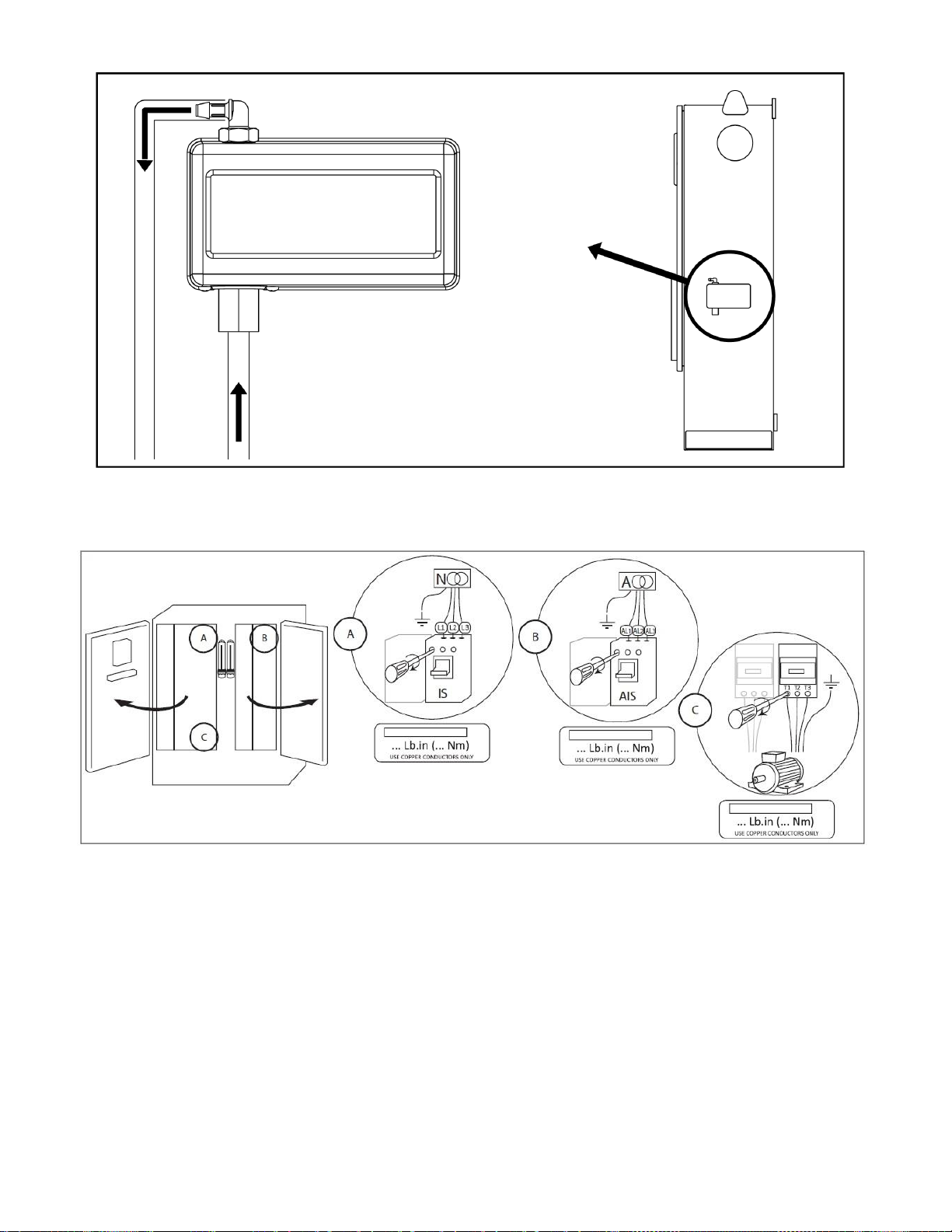
Incoming Power Connections
Incoming normal power is to be connected to terminals located on the disconnecting means IS.
- For 3 phases motor: identified L1-L2 and L3.

8
For the transfer switch, incoming alternate power is to be connected to terminals located on the disconnecting means
AIS (transfer switch side).
- For 3 phases motor: identified AL1-AL2 and AL3.
Motor Connections
Motor wires shall be connected to terminals identified by:
-T1-T2 and T3 located on main contactor (1R) for models FTA3100S and FTA3130S.
It is the responsibility of the installer to obtain connection information on the motor and to assure that the motor is
connected as per the motor manufacturer recommendations. Failure to do so may cause injuries to personnel,
damage the motor and/or the controller and subsequently void warranty on both items.
VFD Reforming
Reforming a VFD is the action of applying voltage to the VFD power path without running a motor. If the drive was
not connected to a voltage source for an extended period of time, the capacitors must be restored to their full
performance before the motor is started. If the Variable Frequency Drive have not been started for a year or more, a
reforming of the VFD needs to be performed. If this is not done, the VFD could be damage from running a motor.
VFD Reforming Required warning: If the FTA31xx detect that the VFD did not run for 365 consecutive days, the
“VFD Reforming Required” warning will be activated. While this warning is active, if a starting request occurs, the
FTA31xx will start using the bypass starting means even if the Mode Switch is in VFD mode. To remove this
warning, a reforming of the VFD must be completed. The “VFD Reforming Required” warning will activate the
“Pump Room” common alarm.
To perform a VFD Reforming:
1- Place the mode switch in “VFD” mode.
2- Enter a valid level 2 password.
3- Go to the “VFD Config” page.
- VFD Reforming start button:
This is to start the VFD Reforming.
- VFD Reforming Duration:
This is to adjust the VFD Reforming duration. It can be changed from 30m to 120m. According to
Schneider, if the VFD required a 1 hour reforming after a 1 year inactivity.
- VFD Reforming Timer:
Show the time remaining in minutes to a VFD Reforming while it is being performed. Only show time
if a VFD Reforming is being performed.
4- Press the “VFD Reforming” button. A textbox will pop up showing that the FTA31xx is performing a
Reforming of the VFD. A stop button can be pressed on this popup to stop the VFD Reforming.
5- The “VFD Reforming Timer” will display the time remaining for the VFD Reforming to be completed. Let the
“VFD Reforming Timer” expire.
The VFD Reforming will be interupted if:
- On the Popup display, the Stop button is pressed;
- A Starting request is activated;
- The Mode Switch is placed in Bypass mode;
When the VFD Reforming is interupted:
-The “VFD Reforming Required” warning is still active;
-The “VFD Reforming Timer” will be reset;
When the reforming is Completed:
-The “VFD Reforming Required” warning is disactivated.
Terminal Strip Descriptions
Electric IO Board
For full terminal strip description consult full manual.

9
Quick Start-Up Guide
The rating label is the most important label. It must be read carefully to ensure the compatibility between the controller
and the installation.
Verify that the controller is installed securely on the wall, or optionally on the mounting stand.
Make sure to drill holes for the motor and power connections and run the cables inside the panel, all in accordance
with the specifications in order to minimize interference with other equipment.
10
Verify and/or install the proper water connections for the water input and the drain. They must be securely installed
and tightened. Refer to the silkscreen markings on the plastic cover.
Connect the normal input power, the alternate input power and the motor on their respective terminals. Secure with
the appropriate torque as indicated on the torque label and verify all connections.
Remove the Graphic Display Terminal from the VFD and place it on the mounting braket on the enclosure door.
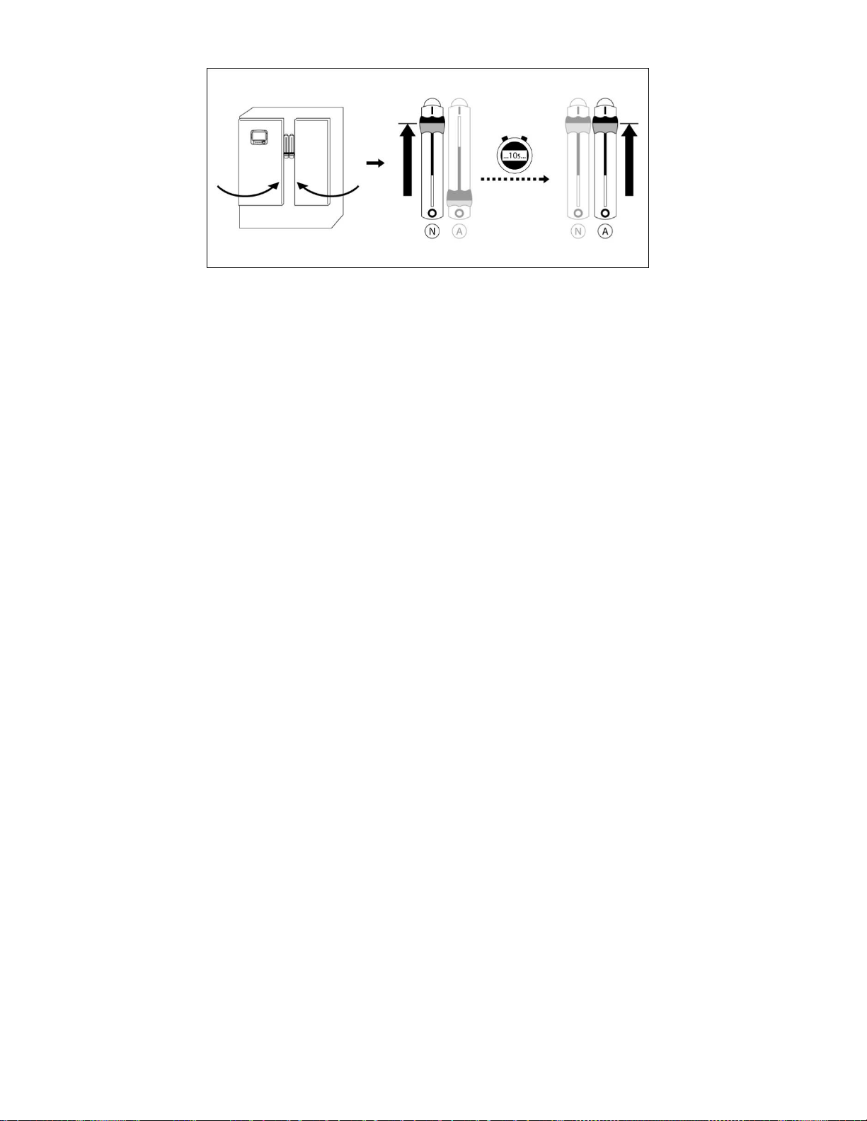
11
Secure the doors in the closed position then put the normal power circuit breaker disconnecting means in the ON
position. Wait 10 seconds for the controller to load correctly, then put the alternate power circuit breaker
disconnecting means to the ON position. Verify the readings on the controller main screen.
VFD Settings –Motor parameters
On the Graphic Display Terminal, go to the “Simply Start” Menu. Verify that all the information on this menu is the
same as the one on the motor name plate:
1- Motor Standard:
Choose between 50 and 60Hz.
2- Nominal Motor Power:
If Motor Standard is set to 60Hz, the Nominal Motor Power is in Hp. If the Motor Standard is set to 50Hz, the
Nominal Motor Power is in kW.
3- Nominal Motor Voltage:
Enter the motor voltage.
4- Nominal motor current:
Enter the motor Full Load Current (FLA or FLC).
5- Nominal motor frequency:
Choose between 50 and 60Hz.
6- Nominal motor speed:
Enter nominal motor speed in rpm.
7- Max frequency:
Should be set to the Nominal Motor Frequency (50 or 60Hz).
VFD Settings –Basic Parameters
Continue on the Simply Start menu and modify or validate the next parameters:
1- Acceleration ramp time
2- Deceleration ramp time
3- Low speed
4- High speed
Refer to the VFD Parameters List for the factory settings values.
VFD Settings –AUTOTUNE
The Autotune procedure allows the VFD to acquire electrical motor characteristics and enhance the VFD
performance. It is recommended to perform an Autotune one time, during the first startup.
While doing the Autotune the VFD will scan the motor and acquire information about the motor.
Before starting the Autotune on the VFD, read the whole procedure. Then perform step by step.
1- Place the Mode switch on the VFD position.
2- On the Mark III. Enter a level 2 password.
3- Go to the “VFD Config” page and press the “VFD Autotune” button. The FTA31xx will close the VFD isolating
contactors. This will energize the VFD power path and allow the VFD to be connected to the motor. The VFD
isolating contactors will remain closed for 3 minutes. During that time, you can perform the Autotune on the
VFD display.

12
4- On the VFD Graphic Display Terminal, go to the “Simply Start” menu
5- Go to the “Autotuning” parameter and press OK to enter the “Autotuning” page.
6- Select “Apply Autotuning” and press OK.
7- A Warning will be displayed on screen. Press OK.
8- Autotune will be performed. You can validate it is completed by going on the “Simply Start” menu and look at
the “Autotuning Status”. It should be at “Autotuning Done”.
9- On the Mark III, press the “Stop” button on the Autotune popup.
10- Place the VFD mode switch on the Bypass position.
NOTE: During Autotuning, the motor might make small movement. Noise development and oscillations of the system
are normal. This may take for several seconds. Do not interrupt the process.
Perform the Autotune on a stopped and cold motor as heat can influence the tuning result.
Once the VFD parameters has been verify and the Autotune has been performed, continue with the “First Start Up”
page. The controller will automatically detect and display the frequency of the power source. It is then possible to
manually choose the frequency of the voltage.
Press “User Login” and enter a valid authorization code.

13
This page is used to verify the supply voltage. It displays the voltage that the controller reads between each phases
for the “Line Voltage” (L), the “Normal Voltage” (N) and the “Alternate Voltage” (A).
If one of these voltages is not the same as the controller's Nominal voltage, a red “X” will be displayed beside the
incorrect voltage reading.
If the Alternate power phases are not in the same order as the Normal power phases, a warning signal will display at
the bottom of the screen. To fix this problem, change the power wire connections A-AL1 and B-AL2 on the Alternate
side Isolation switch.
If the voltage reading are accurate (green check marks), go back to the “Controller Start-up” page and press the
“Motor rotation”.
Place VFD mode switch in BYPASS mode.
Press the “Start” button to start the electric motor and validate that the electric motor is rotating in the correct direction.
If it is not rotating in the correct direction adjust the motor connections as per below. Press the “Stop” button to stop
the electric motor.
Acknowledge that the motor is turning in the right direction by checking the Check on Normal Power selector box.
Place VFD mode switch in VFD mode and Check the “VFD Constant Speed Mode” box.

14
Press the “Start” button to start the electric motor and validate that the electric motor is rotating in the correct direction.
Press the “Stop” button to stop the electric motor. If it is not rotating in the correct direction, go on the Graphic Display
Terminal, and change the “Output phase rotation” PHr parameter on the “Complete settings > Motor parameter >
Motor Control” menu.
Once the motor rotation has been checked, go back to the controller start-up page and press the “Verify pressure”
button.
Choose the desired units of measurement for pressure reading and verify that it matches with the calibrated pressure
gauge installed on the sensing line. Set the Cut-In value according to your system specifications. Cut-Out value will
default to Cut-In plus 10 PSI. To manually enter the cut-out, select the check-box beside it and enter the desired value
(optional).
When finished, press the Service Done button. Any errors will be highlighted in red and, if forced, be logged in the
controller’s event logs.
The “First Start up” is now completed. The controller is fully installed and configured.
From the “Home” page, verify that the displayed values are correct.

15
The “First Start up” is now completed. The controller is fully installed and configured.
To finalize the controller commissioning, it is important to refer to the FTA31xx Complete Setup procedure to adjust
the advanced parameters of the VFD. This will assure the VFD response correctly and in a timely manner to a
pressure drop.
This procedure can only be done by an trained technician.
16
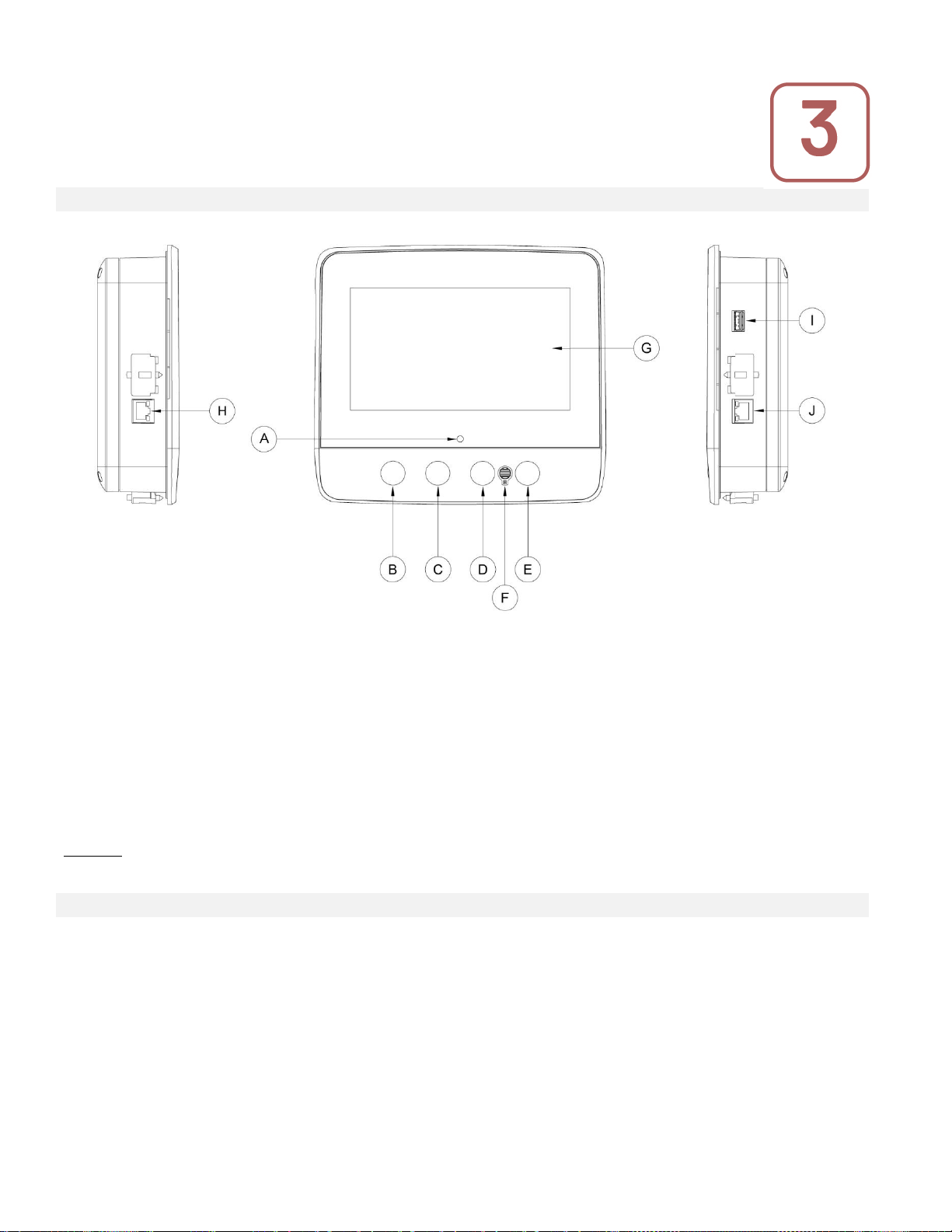
The Mark III+
A: Power LED 3 colors: Pulsing green if the Mark III+ is properly powered.
B: Start button: Used to manually start the motor.
C: Stop button: Used to stop the motor if all starting conditions are gone.
D: Not used.
E: Run Test button: Used to start the manual run test. Be aware that water will flow through the drain during the
test.
F: Alarm buzzer
G: Touch Screen: 7 inch color touch screen LCD with protective cover.
H: CANBUS connector for communication with IO board.
I: Side USB Device connector used for file download, software updates, service reports.
J: Ethernet connector.
Warning
After 2 years of service, the Mark III+ battery may become less efficient and could lose the time after a shutdown.
Alarm Buzzer
The alarm buzzer is activated under default faulty conditions stated by the NFPA20 standard.
Any of these conditions will energize the alarm buzzer but may be silenced, except in some cases, by pressing on
the the “Silence” button on the Alarms page. When silenced, the alarm buzzer restarts ringing if a new fault occurs
or if the alarm conditions remain unchanged after 24 hours. The alarm buzzer automatically stops ringing if alarm
conditions are not present anymore.
Note: Other optional or user defined conditions can also activate the alarm buzzer and can be configured by the
user. See section 5 and verify drawings affixed inside the cabinet for more details.
Main Features

17
First Setup
The First Setup must be done prior to using the controller. Completing the First Setup is the only way to access the
homepage and enable the automatic mode of the controller.
Mark III+: Manual Rebooting Method
If required, here is the procedure to manually reboot the Mark III+:
1- Turn OFF all disconnecting means to de-energize the Mark III+. The Mark III+'s screen should turn black.
2- Press the stop button or wait until the Mark III+'s LED extinguishes.
3- Wait 10 seconds.
4- Turn ON all disconnecting means.
Pressure Transducer Test
The controller will test the pressure transducer at least once a week if no manual run test or no weekly test has
been conducted. During the test, the pressure reading will drop to zero but the controller will not see it as a starting
request. This pressure drop will be recorded in the “Pump Curve” page and in the logs with the message.
Graphic Display Terminal
The FTA31xx is equipped with a ATV630 Altivar Process Variable Speed Drive (VFD) from Schneider. To
modify a parameters on the VFD, use the Graphic Display Terminal situated on the VFD.
It is possible to remove the Graphic Display Terminal and to place it on the enclosure door using the door mounting
kit. The UL IP is Type 12 if the door mounting kit is in the closed position without the Graphic Display Terminal or if
the Graphic Display Terminal is installed. If the door mounting kit is in the open position without the Graphic Display
Terminal, the UL IP is Type 1.
Cooling system
The FTA31xx is rated for an ambient temperature of 40°C. The enclosure is cooled using a combination of fan and
air outlet filter rated NEMA type 12. The fans and air outlet filters must be periodically inspected and cleaned from
excess dust.

18
Home (Menu)
Home
The home page displays all controller statuses and important values of the controller. This includes all voltages,
currents, pressures, motor state and status
Navigation bar: Pressing this icon will open a navigation menu on the left side of the screen:
1. Go to Home page
2. Go to Alarms page
3. Go to Configuration page
4. Go to History page
5. Go to Service page
6. Go to Download Manual page
7. Select Controller Language
System Status: Display the overall system status. For more details, refer to the system status page.
Motor power voltage. Each box represents an individual phase voltage between the two adjacent lines.
Current. Each circle represents an individual line current.
Motor contacts. An animation shows the contactor opened or closed depending on the signal sent to the main coil.
The pressure gauge: It allows for a precise reading of the actual system pressure. The cut-in and cut-out are
represented by a red and green triangle on the gage, allowing a quick comparison between the actual pressure and
the set points.
The VFD frequency gauge. This displays the frequency at which the VFD is running. It is only working when running
using the VFD.
The Setpoint pressure gauge: The VFD SETPOINT PRESSURE is displayed here and needs to be entered on the
VFD using the SoMove software or the VFD graphical display terminal. By default, it is read by an IO board Analog
Input and displayed on the Home page of the MarkIII+.
Home
1
2
3
4
5
6
7

19
Screen Saver
After 5 minutes of inactivity on the Mark III+, the screen will dim it's brightness to 25%. After 10 minutes of inactivity
on the Mark III+, the “Black Screen” screen saver will activate. Its goal is to expand the lifetime of the LCD screen.
The screen saver will be instantly deactivated if the engine is running or if an alarm is activated. To manually
deactivate it, simply touch the screen or any membrane button. After deactivation, the screen saver will always
redirect to the “Home” page. It will also log off any user by resetting the security level to 0 and save any new
modifications to the settings.
Alarms (Menu)
Configuration > Advanced > Alarms
For full alarm list and information consult the full manual, Digitally available, see “Download manual” in section 9
Config (Menu)
Config
For additional information about configuration please consult the full manual, Digitally available, see “Download
manual” in section 9
History (Menu)
History
Alarms
Configuration
History

20
This page is used to access all data related to events, statistics, pressure history, power logs and the downloading
of this information via one of the two USB ports.
-Events: This button leads to the “Events” page, which displays the events from the most recent 500 logs. Each
event log contains the date and time of occurrence as well as a brief description of the event.
-Pressure/Power Curves: This button leads to the “Pressure Curves” / “Power Curves” page accordingly, which
displays all relevant pressure/power information from the most recent 500 logs.
-Saved Logs: This button leads to a page where past logs can be viewed.
-Pump Curve: This button leads to the “Pump Curves” page.
-Statistics: This button leads to the “Statistics” page, which leads to “All Time Statistics”, “First Service Statistics”
and “Last Service Statistics” pages.
-Download: This button leads to the “Download” page, which allows the user to download information, including the
user manual, drawings, logs, statistics and configuration.
For additional information on the History feature refer to the full manual.
Service
Informations on how to reach technical support, concerning the commissioning date, the last service date and the
next service due date is available on this page. It is the client responsibility to make sure that the proper
maintenance is done on the controller. A reminder for the “Service” can be selected from these options: OFF, ½
year, 1 year, 1 ½ years, 2 years and 3 years. The next service will be determined using the last service and the
chosen service interval. This service must be done by an accredited technician.
A proper password must be enter for the “Service Done” button to be available. This button should only be pressed
by an authorized person after a completed service.
The “Live View” page is where the user can grant or refuse the remote access demands.
The “Nameplate Information” page contains all the information found on the nameplate.
The Jockey Pump Cut-Out and Cut-In can be set on this page.
It is possible to install a custom Service card on this page. Contact Firetrol for more information.
Service
This manual suits for next models
1
Table of contents
Other Firetrol Controllers manuals

Firetrol
Firetrol FTA740 Series Product manual

Firetrol
Firetrol Emerson Mark IIXG User manual

Firetrol
Firetrol FTA560F User manual

Firetrol
Firetrol Jockey XG FTA550 Installation instructions

Firetrol
Firetrol FTA570F-AG003E Manual

Firetrol
Firetrol FTA1100 Series Product manual

Firetrol
Firetrol FTA2000 Series Product manual


