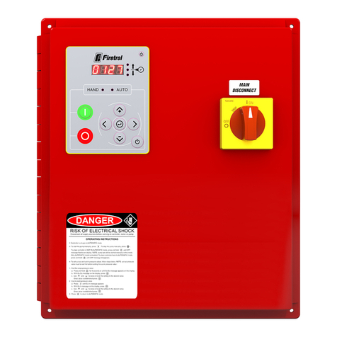
Firetrol FTA570F-AG003E Manual

INSTALLATION AND MAINTENANCE MANUAL
FOR JOCKEY PUMP CONTROLLERS
V2023.07 NS570-01(A) 2

V2023.07 3
TABLE OF CONTENTS
Important Safety Information 4
Introduction 6
JockeyPumpCatalogNumber 6
TechnicalData 6
Storage 7
Installation 8
Seismic 8
Environment 8
Electromagneticcompatibility(EMC) 8
Handling 8
Mounting 8
Toolsandmaterialsrequired: 8
Procedure 9
MakingSystemPressureConnections 9
MakingElectricalConnections 9
ImportantPrecautions 9
Procedure 10
Operator Interface 11
Howtoconfigurethecontroller 12
MethodsofStarting/Stopping 12
Automaticmode 12
Manualmode 12
Offmode 12
Bumpforrotation 12
Commissioning 13
Maintenance 14
Patents 15

V2023.07 4
IMPORTANT SAFETY INFORMATION
DANGER
RISK OF
ELECTROCUTION
PERSONAL INJURY OR DEATH COULD OCCUR.
ENSURE ALL POWER IS DISCONNECTED BEFORE INSTALLING
OR SERVICING THIS EQUIPMENT.
DANGER
Do not attempt to install or perform maintenance on
equipment while it is energized! Death, personal injury
or substantial property damage may result from con-
tact with energized equipment. Always verify that no
voltage is present before proceeding and always fol-
low generally accepted safety procedures. Controller
disconnect switch must be in the “off” position in
order to open the enclosure door. Firetrol cannot be
liable for any misapplication or incorrect installation
of its products.

V2023.07 5
Warning:
This product can expose you to chemicals including
DINP, which is known to the State of California to
cause cancer, and DIDP which is known to the State of
California to cause birth defects or other reproductive
harm.
Warning:
This product can expose you to chemicals including
lead and lead compounds, which are know to the State
of California to cause cancer and birth defects or
other reproductive harm.
Formoreinformationgoto:www.P65Warnings.ca.gov

V2023.07 6
INTRODUCTION
FiretrolJockeyPumpControllersareintendedforusewithfirepumpsystems.Theyareusedfor
pressuremaintenanceinfirepumpinstallationstopreventunnecessarycyclingofthemainfire
pump.
TheyarelistedbyUnderwriters’Laboratories,Inc.,inaccordancewithUL508A,Standardfor
IndustrialControllers.Theyarebuilttomeetorexceedtherequirementsoftheapprovingauthor-
itiesaswellasNEMAandthelatesteditionNFPA70NationalElectricalCode.
TheyalsocomplywiththerequirementsoftheElectromagneticCompatibility(EMC)Directive
2014/30/EU,theLowVoltageDirective(LVD)2014/35/EU,theElectromagneticCompatibility
Regulations(2016No.1091)andTheElectricalEquipment(Safety)Regulations(2016No.1101).
Theseinstructionsareintendedtoassistintheunderstandingoftheinstallationandoperationof
thesecontrollers.Readtheinstructionsthoroughlypriortoconnectingoroperatingthecontroller.
Ifthereareanyunansweredquestions,pleasecontactthelocalFiretrolrepresentativeorthefact-
oryservicedepartment.
Jockey Pump Catalog Number
Model No. Example: FTA570F-AG003E
ModelPrefix:FTA570F
(A)TimerOption:Withprogrammabletimer
(G)MotorCurrentProtection:Manualmotorprotector
(E)Voltage:220-240V1-Phase50/60Hz
(003)HPRating:3HP
Technical Data
Rating Value
RatedOperationalCurrentIe AccordingtotheMotor(HP/kW)
RatedInsulationVoltageUi 690,600(IEC)
RatedOperationalVoltageUe 110/120,220/240,380/415,440/480,
575/600,690
RatedImpulseWithstandVoltageUimp 6000V
RatedOperationalFrequency 50/60Hz
Environmentaltemperature 4°Cto40°C(Optional-5°Cto55°C)
Altitude ≤2000m
Relativehumidity 5%to80%
Pollutiondegree 3
ShortCircuitCurrentRatingIcc(SCCR)(A) Accordingtothecontrollerratinglabel
RatedPeakWithstandCurrentIpk AccordingtoIEC61439-1:2020Table7

V2023.07 7
Storage
Ifthecontrollerisnotinstalledandenergizedimmediately,Firetrolrecommendfollowingthe
instructionsfromthechapter3oftheNEMAICS15standard.

V2023.07 8
INSTALLATION
Seismic
JockeyPumpcontrollersareoptionallyseismicapprovedandhasbeentestedinaccordancewith
theICC-ESAC156,IBC2015&CBC2013standards.Properinstallation,anchoringandmount-
ingisrequiredtovalidatethiscompliancereport.Refertothismanualanddrawingstodetermine
theseismicmountingrequirementsandlocationofthecenterofgravity(youmayneedtocontact
factory).Theequipmentmanufacturerisnotresponsibleforthespecificationandperformanceof
anchoragesystems.Thestructuralengineerofrecordontheprojectshallberesponsiblefor
anchoragedetails.Theequipmentinstallationcontractorshallberesponsibleforensuringthe
requirementsspecifiedbythestructuralengineerofrecordaresatisfied.Ifdetailedseismicinstall-
ationcalculationsarerequired,pleasecontactthemanufacturerfortheperformanceofthiswork.
Environment
JockeyPumpcontrollersareintendedtobeinstalledinlocationswhereambienttemperaturesare
within4°Cand40°Candtherelativehumidityiscontrolledbetween5%and80%.Optionally,the
controllercanhaveanextendedtemperatureofupto55°Candaslowas-5°C,providedthatthe
controllerandthepressurewaterpipesareheatedtopreventwaterfreezinganddamagingthe
electronicandthepipingsystem.
Theyareintendedforpollutiondegree3andshallbeinstalledatanaltitudeofnomorethan2000
meters.Forabnormalinstallationenvironment,consultfactory.
Electromagnetic compatibility (EMC)
JockeyPumpcontrollershavebeentestedforthemoststringentconditionsforemissions(Envir-
onmentB)andimmunity(EnvironmentA),hencecontrollerscanbeinstalledineitherenvir-
onment.Allcontrollersvariantssharethesameelectronicsandcomplytothosecriteriawithout
requiringadditionalmeasures.
Handling
TheweightofeachJockeyPumpcontrollerisindicatedonthepackinglabel.Lightweightcon-
trollersdonotrequirespecialhandlinginstructions,whileheavycontrollersareequippedwithlift-
ingmeansandshouldbehandledfollowingtheguidelinesspecifiedinFiretrol'sdocument"Large
EnclosureSafeHandlingRequirements_PN12162021".
Mounting
Consult the appropriate job plans to determine the controller mounting location.
Tools and materials required:
1. Assortmentofcommonhandtoolsofthetypeusedtoserviceelectromechanicalequip-
ment.
2. Drillfordrillingwallanchorholes.
3. Hole(conduit)punch.

V2023.07 9
4. Handlevel.
5. Tapemeasure.
6. Fouranchorswithboltsandwashers,perenclosure.
Procedure
Refer to the controller dimension drawing for necessary mounting dimensions.
Thecontrolleriswallmountedbyusingatleastfour(4)wallanchors,2anchorsforthetopmount-
ingbracketsand2anchorsforthebottommountingbrackets.Thebracketsaredimensionallyon
thesamecenterlineforeaseinmounting.Thereshouldbeaclearanceofatleast6inchesaround
thecontrollertoallowproperaircirculationaroundtheequipment.
1. Usingeitherthedimensionprintorbymeasuringthedistancebetweenthecenterlinesof
thelowerbracketslots,transcribethisdimensionontothewall.Note:Thebottomedgeof
theenclosureshouldbeaminimumof12”(305mm.)fromthefloorincasefloodingofthe
pumproomoccurs.
2. Drillandputanchorsintothewallforthelowermountingbrackets.
3. Markonthewall,thelocationoftheholesintheuppermountingbrackets.
4. Drillandputanchorsintowallfortheuppermountingbrackets.
5. Installboltsandwashersinloweranchors.
6. Alignholesinuppermountingbracketsandinstallboltsandwashersinanchors.
7. Shimanchorsasnecessarytoensurerearofenclosureisverticallevelandenclosureisnot
stressed.
8. Tightenallanchorbolts.
9. Checktobesureenclosuredooropenandclosesfreelyandthatenclosureislevel.
Making System Pressure Connections
Thecontrollerrequiresone(1)“SystemPressure”connectionfromthesystempipingtothe
enclosure.Theconnectionfitting,1/2”NPTmaleport,isprovidedonthebottom,externalsideof
theenclosureforthispurpose.RefertoNFPA20(orPublicationGF100-30)forcorrectfieldpiping
procedureofthesensinglinebetweenthepumpingsystemandthecontroller.
Making Electrical Connections
Important Precautions
Alicensedelectricianmustsupervisetheelectricalconnections.Thedimensiondrawingsshow
theareasuitableforincomingpowerandmotorconnections.Nootherlocationshallbeused.Only
watertighthubfittingsshallbeusedwhenenteringthecabinettopreservetheNEMAorIPrating
ofthecabinet.
The installer is responsible for adequate protection of the Jockey Pump controller
components against metallic debris or drilling chips. Failure to do so may cause
injuries to personnel, damage the controller and subsequently void warranty.

V2023.07 10
Priortomakinganyfieldconnections
1. Opendoorofenclosureandinspectinternalcomponentsandwiringforanysignsoffrayed
orloosewiresorothervisibledamage.
2. Verifythatthecontrollerinformationiswhatisrequiredontheproject:
1. Firetrolcatalognumber
2. Motorelectricalnameplateinformationmatchescontrollerratingforvoltage,fre-
quency,FLAandHP.
3. Project'selectricalcontractormustsupplyallnecessarywiringforfieldconnectionsin
accordancewiththeNationalElectricalCode,localelectricalcodeandanyotherauthority
havingjurisdiction.
4. Refertotheappropriatefieldconnectiondrawingforwiringinformation.
Procedure
Allfieldconnections,remotealarmfunctionsandACwiringarebroughtintotheenclosurethrough
thetoporbottomconduitentrancesasindicatedonthedimensionaldrawing.
Donotplaceconduitentrancesonthesidesoftheenclosure.
1. Usingahole(conduit)punch,createaholeintheenclosureforthesizeconduitbeingused.
2. Installnecessaryconduit.
3. Pullallwiresnecessaryforfieldconnections,remotealarmfunctions,ACpowerandall
otheroptionalfeatures.Bringenoughwireinsidetheenclosuretomakeupconnectionsto
theappropriateline,loadandcontrolterminalblockpoints.Besuretoconsulttheappro-
priatefieldconnectiondiagramincludedwiththemanual.Forproperwiresizing,refertothe
NationalElectricalCode,NFPA70.
4. Makeallfieldconnectionstotheremotealarmfunctionsandanyotheroptionalfeatures.
5. Connectmotortocontrollerloadterminals.
6. FindnameplateonJockeyPumpmotorandmakenoteofitsfullloadamprating.Veritythe
overloadwithinthecontrollerissetforthatnumberofamps.
7. VerifyAClinevoltage,phaseandfrequencywiththecontrollerdataplateontheenclosure
doorpriortoconnecting.
8. ConnectACpower.
9. Checktoseethatallconnectionsarebothcorrectlywired(inaccordancewiththefieldcon-
nectiondiagram)andtight.
10. Closetheenclosuredoor.

V2023.07 11
OPERATOR INTERFACE
1. LCDscreen
2. Hand-Off-Autoselector
3. Menunavigationbuttons.
1. Down/decreasevalue
2. Enterconfiguration/enter
3. Up/increasevalue
4. Left
5. Right
4. Integratedalarmbuzzer
5. Exitmenubutton
6. Silencebuzzerbutton

V2023.07 12
How to configure the controller
Toentertheconfiguration,presstheenterconfigurationbutton.Usetheupanddownbuttonsto
selectthevaluetoedit,thenpressenter.Usetheincreaseordecreasevaluebuttontoeditthe
value.Holdingthosebuttonswillchangethevaluewithanincreasedspeed.Oncesatisfiedwith
thevalue,presstheenterbutton.
Editeditemsarenotdirectlyappliedtothecontrollerandaremarkedonthescreenwithan
asterisc.Oncesatisfiedwithyournewvalues,exitthemenubyselectingthefirstmenulineand
pressingenter,or,alternativelypresstheexitmenubutton.Aconfirmationpopupwillappearask-
ingyoutoapplythenewvaluestothecontroller,select"yes"thenpressenter.Youmayaltern-
ativelydiscardallchangesmadebyselecting"no".
Methods of Starting/Stopping
Automatic mode
Whenthemodeselectorisinautomatic,thecontrollerwillstartautomaticallyonlowpressure
detectionbythepressuresensor(belowthecut-inthreshold).
Themotorisautomaticallystoppedaftertherestorationofthepressure(abovethecut-out
threshold),afteraprogrammablerunperiodtimer.
Manual mode
Whenthemodeselectorisinmanual,thecontrollerwillrunthemotorcontinuously.
Off mode
Whenthemodeselectorisinoff,themotorcannotbestartedandwillbestoppedifitwaspre-
viouslyrunning.
Bump for rotation
Successivelyapplyingmanualmodeandoffmodetothecontrollercanbeusedtobumpforthe
motorandcheckrotation.Iftherotationisincorrect,turnOFFpowerwiththedoormounteddis-
connect.Swapanytwoexistingmotorleadwiresthatareonthemotorcontactorinthecontroller

V2023.07 13
COMMISSIONING
1. Verify,andadjustifnecessary,themotoroverloadsetting.
2. Forthree-phasemotors,verifythemotorrotationbybumpingthemotor.Incaseofincorrect
rotation,power off the controllerandswaptwowiresatthecontactorloadside.
3. Entertheconfigurationmenuandinputtheappropriatevaluesfor
1. Pressureunitifrequired,intheAdvancedsubmenu;
2. Cut-out1;
3. Cut-in;
4. Timeron;
5. Timeroff.
4. Exittheconfigurationmenuandsavechanges.
5. Placethehand-off-autoselectorinauto.
1Cut-outisrequiredtobeatleast10PSImorethancut-invalueandshouldbeeditedfirst.

V2023.07 14
MAINTENANCE
Firetrolcontrollersarecoveredbyalimitedwarrantyandbackedbya10-yearsservicelifeoruntil
supplylast,providedthatproperinstallation,commissioning,useandmaintenanceofthecon-
trollerismadeasperthisdocumentandanymaintenancestandardapplicable.
Propercontrollerperformancemustbeassertedatleastonceamonthbyexecutingthefollowing:
1. Withthesystembeingatnominalpressure,ensurethatthepressurereadingiswithintol-
erances
2. Performamanualstartsequenceandverifythat
1. Thereisnonuisancetripping
2. Themotorstartsproperlyandisabletoacceleratewithintheexpectedtime
3. Themotorrotatesintheappropriatedirection
3. Performanautomaticstartsequenceandverifythat
1. Themotorstartswhenthepressurefallsbelowcut-in
2. Thepumpisabletorisethepressureabovethecut-out
3. Themotorstopswhenthepressureisabovecut-out,forautomaticstopsystems,or
byperformingamanualstopotherwise
Inadditiontotheabove,thefollowingpreventativemaintenancemustbeperformedatleastonce
year:
1. Turnoffthecontroller
2. Doavisualinspectionoftheexteriorofthecontroller
3. Opentheenclosureanddoavisualinspectionoftheinteriorofthecontroller
4. Makesurethatthereisnodustaccumulationinsidethecontroller
5. Inspectthetightnessofeachdeadcable
6. Putthecontrollerbackinservice

V2023.07 15
PATENTS
Country Title Grant NO
CA Mechanicalactivatorforcontactor 2741881
US Mechanicalactivatorforcontactor US8399788B2
CA Mechanicalactivatorforelectricalcontactor 165512
CA Mechanicalactivatorforelectricalcontactor 165514
US Mechanicalactivatorforelectricalcontactor D803794
US Mechanicalactivatorforelectricalcontactor Patentpending
EP Mechanicalactivatorforelectricalcontactor 002955393-0001/2
AE Mechanicalactivatorforelectricalcontactor Patentpending
AE Mechanicalactivatorforelectricalcontactor Patentpending
CA Firepumpdigitaloperator 163254
US Firepumpdigitaloperatorinterface D770313
AE Firepumpdigitaloperatorinterface Patentpending
EP Firepumpdigitaloperatorinterface 002937250-0001
CA Systemandmethodfordetectingfailureinapressure
sensorofafirepumpsystem
Patentpending
US Systemandmethodfordetectingfailureinapressure
sensorofafirepumpsystem
Patentpending

V2023.07 16
Contact Technical Support Sales
3362ApexPeakway
Apex,NC27502USA
+1-919-460-5200
Table of contents
Other Firetrol Controllers manuals
Firetrol
Firetrol FTA3100S Product manual

Firetrol
Firetrol FTA2000 Series Product manual
Firetrol
Firetrol Emerson Mark IIXG User manual

Firetrol
Firetrol Jockey XG FTA550 Installation instructions
Firetrol
Firetrol FTA740 Series Product manual
Firetrol
Firetrol FTA1100 Series Product manual
Firetrol
Firetrol FTA560F User manual
