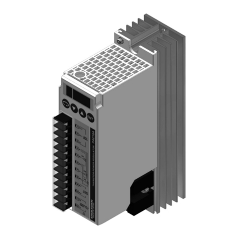
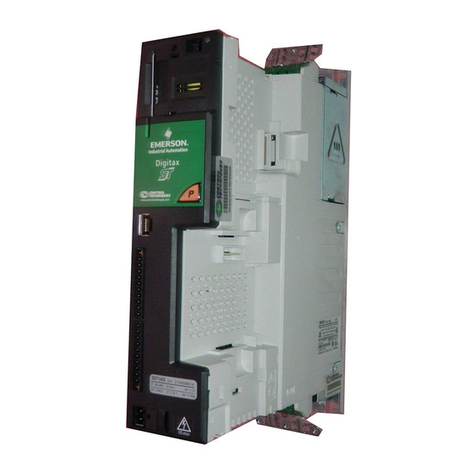
Fireye MicroM Series User manual

1
£
FIREYE
MicroM
FLAME SAFEGUARD CONTROLS
MEC320TS, MEP696, MEUV4
WARNING: Selection of this control for a particular application should be made by a com-
petentprofessional,licensedbyastateorothergovernment.Inappropriateapplicationofthis
product could result in an unsafe condition hazardous to life and property.
DESCRIPTION
The Fireye MicroM Series Flame Safeguard Control is a compact, microprocessor based,
modular burner management system designed to provide automatic ignition and continuous
flame monitoring for commercial sizes of heating and process equipment firing any type of
fuel. The advantages of the MicroM are zero dependence on discrete components previ-
ously used for timing functions thereby extending the stability of the system and reducing
the effects of time and temperature.
A complete MicroM system consists of the relay module, MEC320TS, programmer mod-
ule, MEP696, amplifier module, MEUV4, subbase, 61-3060 or 61-5042 and UV scanner,
UV1A3 or UV1A6. An optional alphanumeric display (ED510) is available that provides
complete English language description of the current operating status as well as diagnostic
history.
To maximize safety the MEP696 provides early spark termination followed by a pilot prov-
ing period. This prevents the unwanted detection of spark generated by a maladjusted pilot
and spark assembly. The air flow switch connected between terminals 7 and 6 must be
closed within 10 seconds after the start of a cycle. Below is a detailed list of the MEP696
operating parameters.
Functions provided on the MEC320TS chassis and MEP696 programmer:
1. Fixed 30 second pre-purge period
2. Ignition terminal 4 shuts off 10 seconds into the Pilot Trial for Ignition
3. 5 second Pilot Proving period
4. Pilot terminal 3 shuts off 5 seconds into the Main Trial for Ignition
5. Post Purge has selectable 0 or 60 seconds duration
6. Release to modulate contacts 1 second after AUTO
7. Lockout occurs if air flow, terminal 6, is not proven 10 seconds into purge
8. Modbus communications allowing for hookup to plc system
9. Dip-switch selectable communication baud rate, 4800, 9600 or 19200 baud
10. Dip-switch selectable pilot trial for ignition timing, 5 or 10 seconds
11. Smart LEDs that provide on board diagnostic lockout information
12. Amplifier test jacks provide uniform 0-10 vdc for flame signal strength
MC-3200
JUNE 6, 2006
APPROVED

2
£
SPECIFICATIONS
Supply: 120 VAC (min. 102, max. 132) 50/60 Hz.
Power Consumption: 12 VA (Operating)
Shipping Weight (Approx): 3 lbs (1.4 kg)
Table 1: AMBIENT TEMPERATURE LIMITS
Table 2: LOAD RATINGS
Table 3: COMPOSITION OF EACH COMBINATION
MAXIMUM MINIMUM
Control 140qF60qC- 40qF- 40qC
Scanner UV1A, UV2,
UV8A, 45UV3
200qF93qC- 40qF- 40qC
45UV5-1007, 45UV5-1009 200qF93qC- 40qF- 40qC
Photocell 45CM1 165qF74qC- 40qF- 40qC
Flame Rod
(Tip 2460 F)
1500qF816qC- 40qF- 40qC
48PT2 125qF52qC-40qF -40qC
CSIA5 140qF60qC-40qF -40qC
COMBINATION NUMBER PILOT FUEL TERMINAL 3 IGNITION TERMINAL 4 MAIN VALVE TERMINAL 5
1 C NO LOAD E
2 B NO LOAD E
3NO LOAD NO LOAD E
4 E A E
5NO LOAD A E
6 D A E
7 D A D
8NO LOAD A D
ABCDE
4.5A Ignition 50 VA Pilot Duty
plus 4.5A ignition
180 VA Ignition
plus motor values
with: 600VA
inrush., 360 VA
open, 250 VA hold
2A Pilot Duty 65 VA Pilot Duty
plus Motor valves
with: 3850 VA
in rush., 700 VA
open, 250 VA hold

3
£
DIMENSIONS
APPROVALS
Underwriters Laboratories Inc.
Listed Guide MCCZ - File MP1537
Listed Guide MCCZ7, Canada - File MP1537
Underwriters Laboratories Inc.
Recognized Components Guide MCCZ2
Recognized Components Guide, Canada MCZZ8 - File MP1537
Factory Mutual System (FM) Approved
2”
(50.8)
1/2”-14 STRAIGHT
FEMALE PIPE THREAD
1” DIA
(25.4)
UV1A UV SCANNER
36” FLEXIBLE CABLE (UV-1A-3)
72” FLEXIBLE CABLE (UV-1A-6)
2 3/8”
(60.3) 1 3/16”
(30)
1/2”
(12.7)
”L”
1/2”-14 NPT
13/16” HEX
(20.6)
15/16” HEX
(23.8)
”L” LENGTH AS SPECIFIED: 12”, 18”, 24” (304.8, 457.2, 609.6)
69ND1 FLAME ROD
5 3/16”
5 3/16”
MOUNTING BASE
5 5/16”
4”
4” 1/2”’
1/2”
3/16” DIA. MOUNTING
HOLES (4)
KNOCKOUTS (12)
FOR 1/2”
CONDUIT
P0
S1
7
S2
8
3
2/N
5
A
4
1
6
3/16” MOUNTING
HOLES
(4)
CAUTION: Published load ratings assume that no control be required to handle
inrush current more often than once in 15 seconds. The use of control switches,
solenoids, relays, etc. which chatter will lead to premature failure. It is important to
run through a test operation (with fuel shut off) following the tripping of a circuit
breaker, a blown fuse, or any instance of chattering of any external current con-
In order for the MicroM to gather and retain statistical and historic data such as
burner hours, burner cycles, system hours and average flame signal, it is necessary
that Terminal 1 be powered at all times. Removing power from Terminal 1 at the
end of the firing cycle causes all data gathered during the previous 16 hours or
lockout occurrence will be lost. For conversions or upgrades from older TFM or
M-Series II controls that use MART1 amplifiers, it is that Terminal 1 be directly

4
£
ORDERING INFORMATION
INSTALLATION OF CONTROL, SCANNERS AND FLAME DETECTORS
Wiring Base
Mount the wiring base on the burner or on a panel. The location should be free from exces-
sive vibration and within the specified ambient temperature rating. The base may be
mounted in any angular position.
All wiring should comply with applicable electrical codes, regulations and local ordi-
nances. Use moisture resistant wire suitable for at least 90 degrees C. Good electrical wir-
ing practice should be followed to ensure an adequate ground system. Refer to Fireye
Service Note SN-100 separately and General Grounding Rules later in this document for
grounding methods.
A good ground system should be provided to minimize the effects of AC quality problems.
A properly designed ground system meeting all the safety requirements will ensure that any
AC voltage quality problems, such as spikes, surges and impulses have a low impedance
path to ground. A low impedance path to ground is required to ensure that large currents
involved with any surge voltages will follow the desired path in preference to alternative
paths, where extensive damage may occur to equipment.
Refer to bulletin MP-5601 for a detailed description of the MEP696 programmer.
Refer to bulletin MC-5000 for additional information about the MicroM product line.
MicroM Chassis Types (Common for all controls, includes dust cover):
MEC320TS 120 VAC input with MED8 daughter board
MEP696 Programer module, fixed 30 second pre-purge, lockout on flame fail, lockout on air flow
opening 10 seconds after start of cycle, selectable baud rate, PTFI, post purge, recycle/
non-recycle air flow interlock, proof of air interlock open at start
MEUV4 UV Amplifier, 3 sec. FFRT, uses UV1A, UV2, UV8A, UV90 and 45UV3-1050 scanners
MED8 Plug in daughter board
UV1A3 Scanner, UV: 1/2” NPT connector, 3 ft. flex conduit
UV1A6 Scanner, UV: 1/2” NPT connector, 6 ft. flex conduit
61-3060 Closed wiring base, surface mounting
61-5042 Open wiring base, cabinet mounting
WARNING: Controls require safety limits utilizing isolated mechanical contacts.
Electronic limit switches may cause erratic operation and should be avoided.

5
£
FIGURE 1. WIRING ARRANGEMENT FOR PILOT IGNITED BURNERS USING MEP696 PROGRAMMER
INSTALLING THE PROGRAMMER AND AMPLIFIER MODULES
WARNING: Remove power from the control before proceeding.
FIGURE 2. .
Remove the dust cover from the chassis. Insert the amplifier module into the slot in the cor-
ner of the chassis and gently push the module into position. Insert the programmer module
into the slot at the right side of the chassis and gently push the module into position.
WARNING: Turn off the power when installing or removing the control.
PV MV
S1
7
35
4
1
A
S2
PILOT VALVE
BLOWER MOTORALARM
8
120VAC
50/60Hz
T
P
FLAME AMPLIFIER
SPARK
KI KF
IGNITION
H
N2
FLAME
SCANNER
OR
CONTACTOR
MAIN FUEL VALVE
OPERATING
CONTROL
KA KB
AIR FLOW
INTERLOCK
FLAME
ROD
ONLY
KL
(WATCHDOG)
F1
6
KP
MODULATE CONTACTS
LOCATED ON
DAUGHTER BOARD
PROGRAMMER
AMPLIFIER

6
£
Replaceable Fuse
The chassis modules are designed with a field replaceable fuse. The fuse is located on the
printed circuit board below the transformer. In the event the fuse becomes OPEN, the Oper-
ating Control, PTFI, and Flame LED’s will light. Terminals 3 (pilot) and 4 (ignition) KF
will not be energized and the control will lock out and indicate Lockout, Check Blown
Fuse. The fuse can blow as a result of an overload condition on Terminals 3, 4, or 5. To
replace the fuse, remove power from the system and using a small screwdriver or similar
tool, install a Fireye replacement fuse (P/N 23-197) or equivalent 10 amp fuse (e.g. Wick-
man # 19373-071-K).
WARNING: Disconnect power before servicing.
FIGURE 3.
MEP696 Programmer Dip Switch Configuration
Note: C refers to switch closed position, closed position is when the switch is toward the printed cir-
cuit board. O refers to switch open position or when the switch is moved away from the printed cir-
cuit board. Indicating arrow on top of programmer cover points toward closed position.
Except for baud rate selection, once the switches are set, they become permanently stored
after 8 hours of continuous operation or they can be manually set through the use of the
SWITCH FUNCTION
654321
C C 4800 BAUD
RATE
SELECTION
C O 9600
O C 19200
O O 19200
C DISABLED POST
PURGEO60 SECONDS
C5PTFI
TIMEO10
C DISABLE PROVE AIR
FLOW OPEN
AT START
OENABLE
C RECYCLE
O NON-RECYCLE
Replaceable
Fuse Location

7
£
optional ED510 display. Refer to the section using the optional ED510 display for detailed
information.
The ED510 display operates at 4800 baud only. To use the ED510 display, power must be
removed and dip switches 1 & 2 must be set in the CLOSED position.
Dipswitch Definitions
Baud Rate: On every application of power, the communication baud rate is determined by
switches 1 & 2. The available selections are 4800, 9600 ad 19200 baud. Note the ED510
requires the baud rate to be set at 4800, switches 1 & 2 closed.
Post Purge: If enabled, Terminal #8 (blower motor or contactor) will remain energized for
60 seconds after terminal #7 or Terminal #6 is detected as open.
PTFI Time: The length of time that Terminal #3 and Terminal #4 will be energized after the
pre-purge period to detect pilot flame.
Prove Air Flow Open: After power is detected on Terminal #7 (limit control) and before
energizing Terminal #8 (blower motor or contactor) no power must be detected on Terminal
#6 (running interlock switch). If power is detected on Terminal #6, the MicroM will hold
for 60 seconds after which safety lockout will occur. On recycle operation, if this is enabled,
Terminal #8 will be de-energized to allow Terminal #6 to open.
Recycle: Applies to air flow interlock opening during the Run condition. If the air flow
interlock (Terminal #6) opens, the control will de-energize Terminals #3, #4 and #5, and if
Recycle is selected a new prepurge period will begin. Lockout and alarm will occur imme-
diately after air flow interlock opening if Non-Recycle is selected.
LED INDICATOR LIGHTS
The MEP696 Programmer Module has 5 LED lights to indicate the operating status of the
control and also to display the coded sequence under locked out conditions. The function of
the lights under a normal operating condition is:
Operating Control: This LED is energized whenever the burner control switch and all
other various limit switches are closed and power is applied to Terminal #7.
Interlock or Air Flow: This LED is illuminated whenever power is detected on Terminal
#6, indicating the air flow switch or other running interlock is closed. If the operating con-
trol is closed and the running interlock switch remains open, this LED will flash at a 1 sec-
ond rate. Lockout will occur if the switch remains open for 10 seconds into the start of the
cycle.
PTFI: This LED is illuminated only during the pilot trial for ignition period and the stabili-
zation period.
Flame: This LED is on whenever a flame signal is detected, and the control is not in a
locked out state.
LED
INDICATORS SWITCHES
(shown in closed or OFF position)
DIP

8
£
Alarm: This LED flashes when an alarm condition is detected and is also used as an
address indicator (see communication).
During an alarm condition, the Alarm LED is made to flash at approximately a 1 second
rate. The remaining four LEDs are illuminated as a coded sequence identifying the reason
for the lockout. For instance, for a LOCKOUT - FLAME FAIL- PTFI, the INTERLOCK,
PTFI and FLAME LED’s will all be lit steady, with the Alarm LED flashing. This remains
true if power is removed and then restored while in a locked out condition.
While in the Idle or Off state, the LEDs are made to flash sequentially every minute to show
the operational status of the control. The LEDs can be tested by pressing and releasing the
Reset push button, while in the Idle or Off state
LOCKOUT CODES
❍ = NOT LIGHTED
● = LIGHTED
✱ = FLASHING
All LED’s Flashing indicates defective programmer.
All MicroM chassis are shipped with a convenient peel off label that can be applied to any
surface (inside cover) for future reference.
MSGN DESCRIPTION OP CTRL AIRFLOW
INTLCK
TFI FLAME ALARM
DEC HEX
6 6 Lockout Line Frequency Noise Detected ●❍❍●✱
7 7 Lockout Flame Fail - TFI ❍● ●●✱
15 0F Lockout Fault Unknown ●●●●✱
16 10 Lockout Amplifier High Count Fail ❍❍❍❍✱
19 13 Lockout Flame Fail - MTFI ❍❍ ●●✱
20 14 Lockout False Flame - STANDBY ❍●❍❍✱
21 15 Lockout Intrlck Open ●●●❍✱
22 16 Lockout Intrlck Closed ❍● ●❍✱
24 18 Lockout Chassis Opto ●●❍●✱
37 25 Lockout Flame Fail - AUTO ❍●❍●✱
39 27 Lockout Fuel Valve State Change ❍❍❍●✱
54 36 Lockout Check Chassis ❍❍❍●✱
55 37 Lockout Check Programmer ❍❍ ●❍✱
56 38 Lockout Check Amplifier ●❍
❍❍✱
58 3A Lockout Amplifier Auto Check Fail ●❍●❍✱
59 3B Lockout Check BLOWN FUSE ●❍●●✱
76 4C Lockout Check Scanner ●●❍❍✱
N/A N/A System Error ✱✱✱✱●

9
£
DIAGNOSTIC MESSAGES - TROUBLESHOOTING GUIDE
PLUG-IN DAUGHTER BOARD
Description
A plug-in board is pre-installed in the MEC320TS chassis to provide local reset, remote alpha-
numeric display, serial communications and normally closed relay contacts.
FIGURE 4. PLUG -IN BOARD LOCATION AND INSTALLATION
POSSIBLE CAUSE SOLUTION
Check Programmer Voltage on Terminal 5 at improper time. Inspect wiring to main fuel valve
Welded watchdog relay Replace chassis
Internal diagnostic failure Replace programmer
Check Chassis Voltage on Terminal 3 or 4 at improper time. Inspect wiring to pilot valve and igniter.
Welded watchdog relay Replace chassis
Chassis Opto Opto-Coupler(s) short circuited Replace chassis
Amplifier High Count Fail Amplifier signal level high Replace Amplifier module
Amplifier Auto Check Fail Flame signal too high Use orifice in sight pipe
Internal Amplifier diagnostic fault Replace Amplifier module
Check Scanner Defective shutter Inspect scanner wiring, replace scanner
UV tube false firing Replace UV tube or scanner
Check Blown Fuse No power detected on terminal 3 Inspect defective pilot valve or igniter
Defective fuse Replace fuse
Line Frequency Noise Detected Spikes detected on AC mains Check for SCR motors or DC drives
Inspect ground system
Fuel Value State Change Terminal 5 (main fuel) detected on during TFI Check external wiring or replace chassis
Check Amplifier Amplifier not passing diagnostic tests Replace Amplifier module
System Error Noise transient Check high energy ignition noise location. Be
sure it is not arcing to chassis or wrapped with
scanner wiring.
STANDOFF
PLUG-IN BOARD
RELEASE
DIRECTION
SERIAL COMMUNICATIONS
REMOTE DISPLAY
RJ45 JACK
RELAY CONTACTS
(RS485)
B
A
MED8

10
£
SEQUENCE TIMING
Table 4: MEP696 Timing Sequence
COMMUNICATIONS
The protocol to be used is Modbus RTU. This is implemented by the master (PC, PLC, etc.) issuing a
poll to the slave (MicroM) and the slave responding with the appropriate message.
A typical format of a poll request is as follows:
DST refers to the logical address of the slave set but using reset pushbutton or ED510.
FNC is the function being requested. FNC 03 is a read request.
ADR is the message number or register number of the data being requested. In Modbus, register
addresses begin at 40001 but is interpreted as address 00.
DAT is the number of words being requested. A word is an integer consisting of 2 bytes.
The normal response from a slave is as follows:
DBC is the data byte count being returned. It must be two times the DAT number from the poll
request.
DATA is the data returned and is always a series of 2 byte integers. If 4 words were requested then
DBC would be 8 and there would be 8 data bytes or 4 data words containing the requested data.
The format of the data is 4800, N, 8, 1 meaning 4800 baud, no parity, and 1 stop bit.
DST FNC ADR
HI
ADR
LO
DAT
HI
DAT
LO
CRC
LO
CRC
HI
DST FNC DBC DATA….
Hi/Lo
CRC
LO
CRC
HI

11
£
Below is a table of currently available messages provided by the MicroM programmers, followed by
a description where necessary.
Messages 00, 05, 08, 10, 15, 21 and 26 are unique in that a limited number of successive registers
can be combined with these requests. For example, a request to message 00 can contain up to 6 data
words. The response to this would contain STATUS, MSGN, GSTAT, TIMER, FLAME and
LOGSTAT. If the requested data word count (DAT) were to be 2 then the response would contain
STATUS and MSGN only. Message 15, last 6 lockouts, can return data ranging from 1 to 6, with 1
referring to the most recent lockout.
Message 26 returns the current operating status as well as stored burner hours and burner cycles as a
snapshot of the entire MicroM system. When all 9 words are requested, the data returned consists of
STATUS, MSGN, FLAME, INPUTS, OUTPUTS, BNRMINS, and BNRCYCS.
MESSAGE
ADDRESS
WORDS
REQUESTED
RESPONSE VALUE
00 1-6 STATUS 83 (053H) = RUN;
202 (0CAH) = LOCKOUT
01 1 MSGN Current message being displayed (see Table 3)
02 1 GSTAT Defines Timer Type
03 1 TIMER Time, Flame, Address
04 1 FLAME Flame Signal
05 1-3 LOGSTAT Current logic module, PURGE, PTFI, AUTO
06 1 INPUTS Input limits state
07 1 OUTPUTS Output relays state
08 2, 4 or 8 SYSMINS System on minutes
10 2 or 4 BNRMINS Burner on minutes
12 2 CYCLES Completed Burner Cycles
14 1 LOCKOUT COUNT Stored Lockout Count
15 1-6 LOCKOUT HISTORY Last 6 Lockouts, first word is most current lock-
out
21 1-2 DEVTYP Programmer device type, 5=EP, 6=EPD,
7=MicroM
22 1 AMPTYP Amplifier Type;
MECD=080H;
MEUV=090H;
MEIR=0A0H;
MERT=0B0H;
MEUVS=0C0H
23 1 PROGTYP Programmer Type
24 2 FLAME SIGNAL
AVERAGES
PTFI and Auto Flame Signal Averages
26 1-9 Combined Status See Description Below
35 6 Most Recent Lockout Data
Returns complete lockout description of stored
lockout history. Includes lockout message,
lockout module, @ burner hours, and @ burner
cycles
41 6 2nd Most Recent Lockout
Data
47 6 3rd Most Recent Lockout
Data
53 6 4th Most Recent Lockout
Data
59 6 5th Most Recent Lockout
Data
65 6 6th Most Recent Lockout
Data

12
£
The MSGN being transmitted is a numerical value and must be interpreted by the communicating
device, which actually is an advantage since this can be made to be whatever message text the end
user wants. In other words, it allows for programming custom messages without actually changing
the message in the programmer.
The MicroM stores its burner on time (Terminal 5 powered) and system on time (L1 powered) in
minutes. Internally, the programmer converts this to hours for display purposes, however the result is
rounded down. The information being supplied by Modbus will be the actual time in minutes and it
is up to the communicating device to do the conversion. Since the maximum value stored in the
MicroM is 9,999,999 minutes, the maximum value in hex therefore, is 98967FH and comprises of
two data words. The maximum cycle count is 999,999 decimal or 0F423FH, still two data words. As
an example, the System on Minutes data is transmitted from the MicroM to the interface as high
word / low word as shown below:
Note: Data from address 9 cannot be accessed directly.
All values are represented in a HEX or base 16 format.
GSTAT determines the type of value TIMER represents. TIMER can be a running timer such as is
used in purge, a flame signal or meaningless. Only the lower nibble of GSTAT has any value. If this
value is 0 then the TIMER value has no meaning. The value in TIMER is a background minute timer
in the MicroM and should be ignored. If GSTAT is between 4 and 7, the TIMER represents the cur-
rent value flame signal. If GSTAT is a 1, 2, or 3 then TIMER represents a running timer value.
The baud rate of the MicroM is fixed at 4800 bits per second. The format of the data is 8 data bits, no
parity and 1 stop bit. Due to the RS485 format, the communication format is considered half-duplex.
That is, only one user is permitted on the communication lines at a time.
The information contained in INPUTS and OUTPUTS represents the status of the interlocks and
relays respectively. For the INPUTS, a 1 in the interlock position defines the interlock as being on or
energize where the 1 in any bit position in the OUTPUT register signifies the relay as being ener-
gized.
Reset, Scrl and Mode represent the keypad located on the ED510 display. A ‘0’ in any of these posi-
tions indicates the switch is depressed. A ‘1’ in the opto-coupler position indicates the opto-coupler
is on or interlock closed.
A ‘1’ in any terminal position indicates the relay is energized. Term 4 indicates the state of K1 relay,
located in the MEP500 series programmers.
It is suggested that repeated polling interval not be less than 200 mSec per request. Requesting
data such as burner minutes, system minutes and burner cycles be kept at a minimum due to
the amount of processing time required to gather that data.
MESSAGE ADDRESS 8 MESSAGE ADDRESS 9
HIGH WORD LOW WORD
HIGH BYTE LOW BYTE HIGH BYTE LOW BYTE
098H 96H 7FH
INPUTS
Term 5 Term 3 Term 6 Term 7
Reset Scrl Mode RF Pilot Intrlck OpCntrl Ref
OUTPUTS
Term 8 Term A Term 3 Term 5 Term 4
N/A N/A N/A Blower Alarm Pilot Main Fuel MTFI

13
£
Table 1: Logic Dispatch
LOGIC DISPATCHER
VALUE MicroM
HEX DEC
45H 69 MPOSTIDLE
46H 70 MPREPURGE1
47H 71 MPURGE
48H 72 MTFI
49H 73 MSTABLE
4AH 74 MTFMF
4BH 75 MAUTO
4CH 76 MSHTDWN1
4DH 77 MSHTDWN2
4EH 78 MIDLE

14
£
Addressing Modes
For communication in a multi-burner or multi-control environment, each MicroM must have a
unique address. The range of address allowed within the MicroM is 0 to 31 allowing for a possible
32 units to be connected in a single multi-drop node. As shipped the default address is 0. The address
of the MicroM may be set using two methods. Using the ED510 display, it is necessary is SCRL to
the PROGRAM SETUP menu and enter that submenu with the MODE key. SCRL down until the
display indicates UNIT ADDRESS with the actual address of the MicroM being displayed on the top
line of the display. Pressing and releasing the RESET key will cause the address to increment. The
Table 2: Message Description
DEC HEX MicroM Message
1 1 L1-7 OPEN
2 2 FALSE FLAME
3 3 STARTING BURNER
44
5 5 INTRLCK OPEN
6 6 LOCKOUT LINE FREQUENCY NOISE DETECTED
7 7 LOCKOUT FLAME FAIL - PTFI
8 8 UNIT ADDRESS
99 MTFI
10 0AH IGNITION TIMING
11 0BH
12 0CH FLAME SIGNAL
13 0DH CYCLE COMPLETE
14 0EH OFF
16 10H LOCKOUT AMPLIFIER HIGH COUNT FAIL
19 13H LOCKOUT FLAME FAIL – MTFI
20 14H LOCKOUT FALSE FLAME – STANDBY
21 15H LOCKOUT INTRLCK OPEN
22 16H LOCKOUT INTRLCK CLOSED
23 17H INTRLCK CLOSED (PROVING AIR FLOW OPEN AT START)
24 18H LOCKOUT OPTO FAILURE
30 1EH FALSE FLAME
37 25H LOCKOUT FLAME FAIL - AUTO
39 27H FUEL VALVE STATE CHANGE
40 28H AIR FLOW CLOSED
49 31H LOCKOUT FLAME FAIL - PTFI
54 36H LOCKOUT CHECK CHASSIS
55 37H LOCKOUT CHECK PROGRAMMER
56 38H LOCKOUT CHECK AMPLIFIER
58 3AH LOCKOUT AMPLIFIER AUTO CHECK FAIL
59 3BH LOCKOUT CHECK BLOWN FUSE
76 4CH LOCKOUT CHECK SCANNER

15
£
address after 31 is 0. The second method is to use the local reset located on the plug-in board. It is
first necessary to open the operating control (L1-7) to have the MicroM in the IDLE or STANDBY
position. Depressing the reset switch for greater than 10 seconds will cause the address of the
MicroM to be displayed in a binary format on the LEDs located on the programmer board. Because
the default is address 0, and since address 0 would mean no LEDs would be lit; the ALARM LED is
made to flash when the address is 0. The OP CTRL LED is the least significant bit while the
ALARM relay is the most significant bit. To increment the address counter, depress and release the
RESET push button and observe the LED pattern. If the RESET switch is untouched for 30 seconds
the current address displayed will be stored to memory and the MicroM will automatically exit the
address mode.
TEST JACK VOLTAGE
For all amplifiers, the MicroM provides a uniform 0-10 volt signal to represent the flame signal
strength. A signal reading greater than 4 volts is considered sufficient to provide reliable operation.
This same signal is also available in a numerical format on the ED510 display. The chart below cor-
relates the test jack voltage to the numerical value. The signal clamps at 10 volts at a numerical value
greater than 42 and the numerical value clamps at 80.
0
1
2
3
4
5
6
7
8
9
10
616202428323640 60 80
AMPLIFIER TEST JACK VOLTAGE VS. ED510 DISPLAY BOARD
TEST JACK VOLTAGE

16
£
NOTICE When Fireye products are combined with equipment manufactured by others and/or inte-
grated into systems designed or manufactured by others, the Fireye warranty, as stated in its
General Terms and Conditions of Sale, pertains only to the Fireye products and not to any
other equipment or to the combined system or its overall performance.
WARRANTIES FIREYE guarantees for one year from the date of installation or 18 months from date of
manufacture of its products to replace, or, at its option, to repair any product or part thereof
(except lamps, electronic tubes and photocells) which is found defective in material or
workmanship or which otherwise fails to conform to the description of the product on the
face of its sales order. THE FOREGOING IS IN LIEU OF ALL OTHER WARRANTIES
AND FIREYE MAKES NO WARRANTY OF MERCHANTABILITY OR ANY OTHER
WARRANTY, EXPRESS OR IMPLIED. Except as specifically stated in these general terms
and conditions of sale, remedies with respect to any product or part number manufactured
or sold by Fireye shall be limited exclusively to the right to replacement or repair as above
provided. In no event shall Fireye be liable for consequential or special damages of any
nature that may arise in connection with such product or part.
FIREYE MC-3200
3 Manchester Road JUNE 6, 2006
Derry, New Hampshire 03038 USA
www.Fireye.com
£
Other manuals for MicroM Series
2
This manual suits for next models
3
Table of contents
Other Fireye Controllers manuals
Fireye
Fireye NEXUS NX6100 series User manual
Fireye
Fireye BurnerPRO BP110 User manual
Fireye
Fireye PPC5000 User manual
Fireye
Fireye FX Series User manual
Fireye
Fireye PPC4000 SERIES User manual
Fireye
Fireye SureFire II User manual
Fireye
Fireye PPC6000 Series Manual
Fireye
Fireye D10 Series User manual

Fireye
Fireye SB Series User manual
Fireye
Fireye PPC6000 Series Operating instructions

