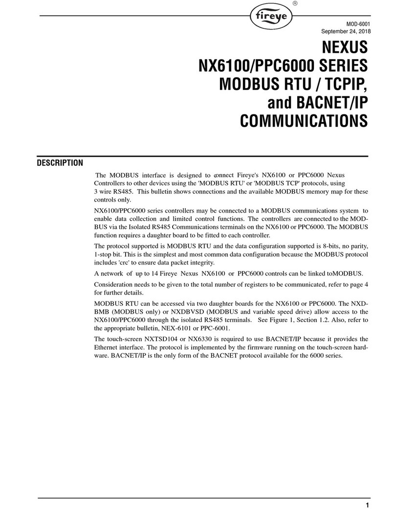
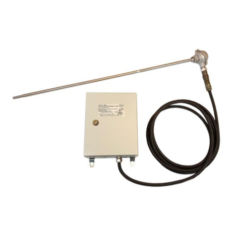
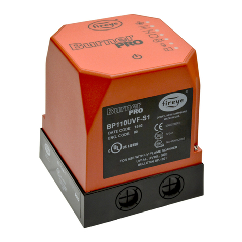
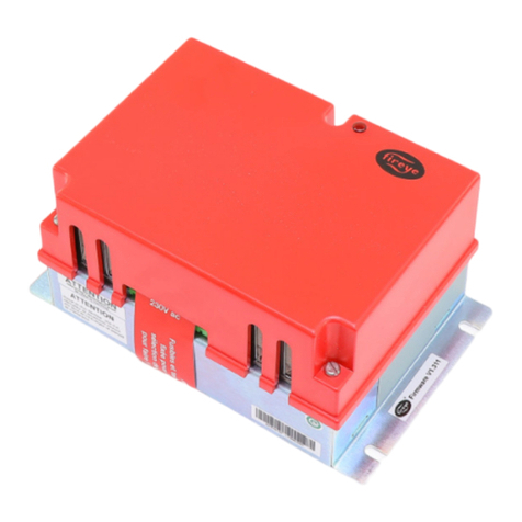
Fireye FLAME-MONITOR E110 User manual

1
®
DESCRIPTION
The Fireye®E110 FLAME-MONITOR™ System is a microprocessor based burner management
control system designed to provide the proper burner sequencing, ignition and flame monitoring pro-
tection on automatically ignited oil, gas, and combination fuel burners. In conjunction with limit and
operating controls, it programs the burner/blower motor, ignition and fuel valves to provide for
proper and safe burner operation. The control also provides current operating status and lockout
information in the event of a safety shutdown. The manner in which this information is displayed is
dependent on the type of programmer (EP or EPD) and display module (ED510 or ED500).*Refer
to Flame-Monitor PROGRAMMER SELECTION later in this document for the various combina-
tions of programmer and display modules.
The E110 consists of the EB700 chassis, dust cover, and shortened mounting screw (P/N 48-1836).
The display module (ED510), if required, must be ordered separately. Interchangeable programmer
and flame amplifier modules allow for complete versatility in selection of control function, timing,
and flame scanning means. Functions such as pre-purge, recycling interlocks, high fire proving inter-
lock, and trial for ignition timing of the pilot and main flame are determined by the programmer
module. The E110 Flame-Monitor can be used with ultra-violet, auto-check infrared, flame rod, or
self-check ultraviolet flame scanners by choosing the proper amplifier module.
The eighteen (18) terminal wiring base allows for many functional circuits including motors, valves,
and ignition transformers as well as multiple interlocks such as high purge, low purge, fuel valve and
running interlock circuits. The E110 uses the same wiring base as the Fireye E100 Flame-Monitor
control, D Series and C Series Controls and is directly interchangeable with most models without
rewiring.
Additional functions of the Flame-Monitor system include:
•A non-volatile memory which allows the control to remember its history and present position
even when power is interrupted.
•A constant flame signal read-out via display module or 0-10 VDC output (EPD
programmers only).
•Read-out of main fuel operational hours and complete cycles via display module.
•Modbus communications via RS485 multi-drop link.
•Dipswitches located on the EP programmer to allow selectable purge time.
•A run/check switch which allows the operator to stop the program sequence in any of three dif-
ferent positions (Purge, PTFI, or Auto).
•Remote Display Capability.
•Annunciate 16 additional interlocks using E300 Expansion Module.
* The ED500 display was the predecessor of the ED510 display and uses an older design. It does not have the latest features
of the ED510 display module.
E110 FIREYE
FLAME-MONITOR™
BURNER MANAGEMENT CONTROL
FOR USE WITH THE
MICROPROCESSOR-BASED
EP AND EPD STYLE
PROGRAMMER MODULES
E-1101
MARCH 28, 2013
APPROVED
E110 with ED510 Display Module

2
®
FLAME-MONITOR SPECIFICATIONS
Supply Voltage:
E110: 120 VAC (+10%, -15%) 50/60 Hz
E120: 220 VAC (+10%, -15%) 50/60 Hz
Power Consumption: 25 VA
Shipping Weight: (E110 Approx.) 5 lbs. (2.3kg)
OPERATING TEMPERATURE LIMITS
LOAD RATINGS
Maximum Simultaneous Connected Load: 2000 VA
CONTROL MAXIMUM MINIMUM
E110, E120, EB700, EB701 140°F 60°C - 40°F - 40°C
EP, EPD Programmers 140°F 60°C - 40°F - 40°C
All Amplifiers 140°F 60°C - 40°F - 40°C
ED510 Display 140°F 60°C 32°F 0°C
Scanner UV1A, UV2, UV8A,
45UV3, UV90
200°F 93°C - 40°F - 40°C
45UV5-1007, 45UV5-1009 200°F 93°C - 40°F - 40°C
Flame Rod
(Tip 2460 F)
1500°F 816°C - 40°F - 40°C
48PT2 140°F 60°C - 40°F - 40°C
Humidity: 85% R.H. (Non-condensing)
TERMINAL TYPICAL LOAD A. Maximum Rating @120V-50/60Hz B. Alternate Rating @120-50/60Hz
5, 6 Individually or
Combined
Pilot Valve(s) and Igni-
tion Transformer(s)
50VA Pilot Duty (Solenoid Valves)
plus 500VA (Transformer)
125VA Pilot Duty Solenoid Valves plus
250VA (Transformer)
7 Main Fuel Valve(s) 250VA Pilot Duty (Solenoid Valve) 1250 VA Opening 500 VA Holding
(Motorized Valve) plus 65 VA Pilot Duty
(Solenoid Valve)
M Burner/Blower Motor 9.8 F.L.A. * 58.8 L.R.A. 240 VA Pilot Duty (Motor Starter Coil)
10-11-12-X Modulator 125 VA Pilot Duty
AAlarm 50 VA Pilot Duty
Terminal ratings may be selected from either column A or B: (select the rating from the column for each terminal which best applies to
the connected load on that terminal).
* F.L.A. = full load amps L.R.A. = locked rotor amps
CAUTION: While programmers are mechanically interchangeable in that they mate with
a common wiring base, you should select the correct model for your application. Inappro-
priate application of a control could result in an unsafe condition hazardous to life and
property. Selection of a control for a particular application should be made by a competent
professional, such as a boiler/burner service technician licensed by a state or other govern-
ment agency.

3
®
ELECTRICAL RATINGS
VA ratings (not specified as pilot duty) permit the connection of transformers and similar devices
whose inrush current is approximately the same as their running current.
VA Pilot Duty ratings permit the connection of relays, solenoid valves, lamps, etc. whose total oper-
ating load does not exceed the published rating and whose total inrush current does not exceed 10
times the rating.
Running and locked rotor ratings are intended for motors. VA and VA Pilot Duty loads may be
added to a motor load provided the total load does not exceed the published rating.
WARNING: This equipment is a Class B digital apparatus which complies with the Radio
Interference Regulations, CRC c.1374.
CAUTION: Published load ratings assume that no contact be required to handle inrush cur-
rent more often than once in 15 seconds. The use of control switches, solenoid, relays, etc.
which chatter will lead to premature failure. It is important to run through a test operation
(with fuel shut off) following the tripping of a circuit breaker, a blown fuse, or any known
instance of chattering of any external current consuming devices.
APPROVALS
Underwriters Laboratories Inc.:
MCCZ File MP 1537
Controls, Primary Safety - Listed
MCCZ2 File MP1537
Controls, Primary Safety - Component
MCCZ7 File MP1537
Controls, Primary Safety Certified for Canada
MCCZ8 file MP1537
Controls, Primary Safety Certified for Canada - Component
Acceptable by: Industrial Risk Insurers (I.R.I.)
Factory Mutual Approved
Note: E120 is FM approved only.
WARNING: This equipment generates and can radiate radio frequency energy, and if not
installed and used in accordance with the instruction manual may cause interference to radio
communications. It has been tested and found to comply with the limits for a Class A comput-
ing device pursuant to Subpart J of part 15 of FCC Rules, which are designed to provide rea-
sonable protection against such interference when operated in a commercial environment.
Operation of this equipment in a residential area is likely to cause interference in which case
the user, at his own expense, will be required to take whatever measures which may be
required to correct the interference.

4
®
APPLICABLE BULLETINS
All bulletins are available in .pdf format at www.fireye.com.
FLAME AMPLIFIER SELECTION
SCANNER SELECTION
E120, Flame-Monitor Chassis, 220 VAC Operation, FM approved E-1201
Programmers, Non-Recycle Operation EP-1601, EPD-1601
Programmers, Recycle Operation EP-2601, EPD-2601
Programmers, Non-Modulating EP-3801, EPD-3801
Amplifiers EAMP1
Display, ED510 ED-5101
Expansion Module E-3001
FIREYE P/N DESCRIPTION USE WITH SCANNER
EUV1 Standard UV Amplifier UV1A, UV8A 45UV3, UV2
E1R1 Autocheck Infrared Amplifier 48PT2
E1R2 Autocheck Infrared Amplifier (For special applications -
high sensitivity—consult factory)
48PT2
E1R3 Autocheck Infrared Amplifier. (Without oil fog rejection
spray circuitry.)
48PT2
ERT1 Rectification Amplifier 69ND1
EUVS4 Self-Check UV Amplifier 45UV5-1007/1008/1009
FIREYE P/N DESCRIPTION USE WITH
SCANNER
BULLETIN
48PT2-1003
48PT2-9003
48PT2-1007
48PT2-9007
4-263-1
Infrared 1/2" straight mount 96" TC-ER
Infrared 1/2" 90angle mount 96" TC-ER
Infrared 1/2" straight mount 48" TC-ER
Infrared 1/2" 90angle mount 48" TC-ER
Replacement photo detector
E1R1, E1R2,
or E1R3
SC-103
UV1A3
UV1A6
UV8A
UV2
UV2A6
45UV3-1050
UV90-3
UV90-6
UV90-9
UV 1/2" straight 36" TC-ER cable
UV 1/2" straight 72" TC-ER cable
UV 1/2" 90head 72" unshielded leads
UV 3/8" straight 36" TC-ER cable
UV 3/8" straight 72" TC-ER cable
UV 3/4" cast aluminum housing 8' cable
UV 90° lateral view with 36” flex conduit
UV 90° lateral view with 72” flex conduit
UV 90° lateral view with 108” flex conduit
EUV1 SC-102
69ND1-1000K4
69ND1-1000K6
69ND1-1000K8
Flame rod 12", 1/2" N.P.T. mount
Flame rod 18", 1/2" N.P.T. mount
Flame rod 24", 1/2" N.P.T. mount
ERT1 SC-103
45UV5-1007
45UV5-1008
45UV5-1009
4-314-1
Self-check UV 1" British thread mounts, 230V
Self-check UV 1" British thread mounts, 120V
Self-check UV 1" N.P.T. threads, 120V
Replacement UV tube
EUVS4 SC-101

5
®
FIREYE®FLAME-MONITOR™ Selection Guide
1. SELECT CHASSIS
E110 FLAME-MONITOR, 120 VAC operation
E120 FLAME-MONITOR, 220 VAC operation
2. SELECT PROGRAMMER
EP Programmers provide selectable operation (e.g. extended purge time)
EPD programmers have integral LED indicator display.
3. SELECT DISPLAY
Required for EP Programmers, Optional for EPD programmers
ED510 2 line x 16 character LCD display.
4. SELECT AMPLIFIER
Requires appropriate flame scanner.
5. SELECT WIRING BASE
60-1386-2 Surface mount
60-1466-2 Panel mount
6. SELECT ACCESSORIES
(on following page).
NON-RECYCLE OPERATION RECYCLE OPERATION DESCRIPTION NON-MODULATION DESCRIPTION
EP160 EPD160 EP260 EPD260 10 and 15 sec. TFI EP380, EP387, EPD380 30 sec. purge
EP161 EPD161 EPD261 Extended MTFI EP381 EPD381 15 sec. purge
EP165
EP166
Pilot stabilization
Pilot stabilization
EP382 EPD382 1 sec. purge
EP170 EPD170 EP270 EPD270 Early spark termination EP390 EP390 90 sec. purge
NOTE: The EP programmers listed above are available in both Spanish and French languages.
Consult factory or your local Fireye distributor for ordering information.
DESCRIPTION USE WITH SCANNER
EUV1 Standard ultra-violet amplifier UV1A, UV2, UV8A, 45UV3,
UV90
EUVS4 Self-check ultra-violet amplifier 45UV5-1007, 1008, 1009
E1R1 Autocheck infra-red amplifier 48PT2
E1R2 Autocheck infrared amplifier (with high sensitivity circuitry) 48PT2
E1R3 Autocheck infrared amplifier (without oil fog rejection circuitry) 48PT2
ERT1 Flame rectification amplifier 69ND1

6
®
FIREYE P/N DESCRIPTION BULLETIN
ED510 Display Module (2 line x 16 characters LCD Display) ED-5101
129-145-1, -2, -3 Remote Display Mounting Kit (for ED510) with 4', 8' or 2' cable respectively E-8002
E350-3, -6 Expansion Module cables in 3' and 6' lengths E-3001
ED150-3, -6, -15, -25 Remote Reset cables in 3', 6', 15' and 25' lengths E-8001
ED600 Multi-port Cable Adapter E-8001
ED610 Multi-port Adapter (for ED510 and RS485 communications) E-8002
E500-3 Communication Interface (up to 6 Flame-Monitor controls) E-5001
EC485 RS232 to RS485 converter for direct connect EC-4851
ED512-2, -4, -8 Communications interface cables in 2', 4' and 8' lengths E-8002
ED580-2, -4, -8 Remote display cables in 2', 4' and 8' lengths E-8002
IT1000 Wireless communication monitor system for up to 10 Flame-Monitor Controls INT-1000

7
®
FLAME-MONITOR Ordering Information
E110 Flame-Monitor (One required) ED510 Display Module
Required with EP Programmers
Optional with EPD Programmers
Amplifier Module (One Required) Wiring Base (One Required)
E1R1
E1R2
E1R3
EUV1
EUVS4
ERT1
60-1386-2
60-1466-2
Programmer Module (One Required)
EP Programmer
EP160
EPD Programmeror
EP161
EP165
EP166
EP170
EP260
EP265
EP270
EP380
EP381
EP382
EPD160
EPD161
EPD170
EPD260
EPD261
EPD270
EPD380
EPD381
EPD382
EPD390
E110 consists of:
EB700 Chassis
EC600 Dust Cover
Mounting Screw (48-1836)
Surface Mount
(shown)
Cabinet Mount
EP programmers must have an Eng. code of 28 or
later (e.g. 9414-28). EPD Programmers must have
an Eng. code of 02 or later.
EP387
EPD167
EP390

8
®
FLAME SCANNERS
CAUTION: The UV1, UV2, UV8A, UV90 and 45UV3 ultra-violet flame scanners and associ-
ated amplifier modules are non-self checking UV systems and should be applied only to burn-
ers that cycle often (e.g.: a minimum of once per 12 hours) in order for the safety checking
circuit to be exercised. If component checking is required during burner operation for con-
stantly fired burners, utilize the self-checking ultra-violet flame scanners (45UV5) with asso-
ciated amplifier module (EUVS4), or the infrared flame scanner (48PT2) with associated
Auto Check amplifier (E1R1, E1R2, E1R3).
FLAME-MONITOR PROGRAMMER SELECTION
All programmers for the Flame-Monitor Series are designated with the prefix "EP" or “EPD.” The
functional operation, flame failure response time, purge timings, firing rate motor circuit, trial for
ignition timings, recycling function and display messages are determined by the programmer.
Following is a chart of the most common programmers. Refer to the appropriate product bulletin for
a detailed description of the operation of each programmer.
Take note of the programming sequence chart for each programming module for the proper explana-
tion of pre-purge timings.
WARNING: THE INAPPROPRIATE SELECTION OR APPLICATION OF A PROGRAM-
MER MODULE COULD RESULT IN AN UNSAFE CONDITION HAZARDOUS TO LIFE
AND PROPERTY. The various programmer modules (EP(D)160, EP(D)260 and EP(D)380)
are interchangeable because they plug into a common chassis. Changing the dipswitches
modifies the operation of each programmer module. Care should be taken to insure the
proper dipswitch settings. Refer to the appropriate programmer bulletin for dipswitch set-
tings. Selection of the programmer module and setting the dipswitches for a particular appli-
cation should be made by a competent professional, such as a Boiler/Burner technician
licensed by a state or government agency, engineering personnel of the burner, boiler or fur-
nace manufacturer (OEM) or in the performance of duties based on the information from the
OEM.
UV90
45UV5
UV8A
45UV3-1050
UV1A
69ND1
48PT2-9000

9
®
PROGRAMMER AND DISPLAY MODULE COMPATIBILITY
All programmers for the Flame-Monitor Series are designated with the prefix “EP” or “EPD.” The
ED510 is a 2 line by 16 character LCD display with keypad to provide both current and historical
information pertaining to the operation of the control. Refer to Bulletin ED-5101 for a complete
description of the features and capabilities of the ED510 display module. The ED500 is an eight
character LED display, was the predecessor to the ED510 and does not have the latest features of the
ED510 display module. EP style programmers with an Engineering code of 28 or later (e.g. 9414-28)
are compatible with both the ED510 and ED500 display module. EP style programmers with an
Engineering code before 28 are only compatible with the ED500 display. The EPD style program-
mers (with an Engineering code 02 or later) are compatible with the ED510 display module as well.
Note: The EPD style programmers do not require a display module to function.
FIREYE
PART
NUMBER
Pre-purge
program-
ming
(Seconds)
Proven
High Fire
Purge
Interlock
(D/8 Ckt)
Proven
Low Fire
Start
Interlock
(M/D Ckt)
Intermittent
Ignition/
Pilot
Interrupted
Ignition/
Pilot
Early Spark
Termination
Pilot
Trial-for-Ignition
Main
Trial-for-Ignition
Running
Interlock
(3/P CKT)
Firing Rate
Motor
Circuit
EPD/EP2PROGRAMMERS
EPD160
EP160
EPD1678
301
Supervised
Yes Yes No Yes No 10
10
10
15
Non Recycle Yes
EPD161
EP161
30 1
Supervised
Yes Yes No Yes No 10
10
10
30
Non Recycle Yes
EP165 7 301
Supervised
Yes Yes No Yes No 10
10
—
10 6Non Recycle Yes
EP1667301
Supervised
Yes Yes No Yes No 10
10
—
15 6Non Recycle Yes
EPD170
EP170
30 1
Supervised
Yes Yes No Yes Yes 5
10
—
10
Non Recycle Yes
EPD260
EP260
30 1No Yes No Yes No 10
10
10
15
Recycle Yes
EPD261 30 1No Yes No Yes No 10
10
10
30
Recycle Yes
EPD270
EP270
30 1No Yes No Yes Yes 5
10
—
10
Recycle Yes
EPD380
EP380
EP3878
30 No Yes Yes3Yes Yes 410
10
10
Intermittent 3
Recycle 5None
EPD381
EP381
15 No Yes Yes3Yes Yes 4 10
10
10
Intermittent 3
Recycle 5 None
EPD382
EP382
0 No Yes Yes3Yes Yes 4 10
10
10
Intermittent 3
Recycle 5 None
EPD390
EP390
90 No Yes Yes3Yes Yes 4 10
10
10
Intermittent 3
Recycle 5None
All programmers have a maximum 4 second Flame Failure Response Time (FFRT) with the exception of the EP165 and EP166 (2 sec. FFRT).
All EPD Programmers and EP Programmers have selectable 3-P Proven Open to Start feature via dipswitch.
1These programmers add a 30 second waiting period to the prepurge while the firing rate motor is driven to the low fire position.
2 Purge timings can be extended via dipswitches of EP style programmers.
3Selectable intermittent or interrupted (15 sec. MTFI) operation of terminal 6 via dipswitch (EP models only).
4These programmers can use terminal “X” for spark termination. This requires jumpering terminals 5 and 10 on the wiring base. PTFI timing is 5 seconds on terminal “X.”
5Selectable Recycle or Non-Recycle Operation via dipswitch.
6During MTFI terminal 6 is energized for 5 seconds (pilot stabilization) before energizing terminal 7 for 10 seconds for EP165 and 15 seconds for EP166 only.
7EP165 will lockout on power interruption.
8The EPD167 and EP387 wait indefinitely for the low fire start switch (M-D) to close.
Term 5
Term 6
Term 5
Term 6

10
®
For a complete system, choose one of each of the following:
- Chassis - Flame Detector
- Programmer Module - Wiring Base
- Amplifier Module
WARNING: Installer must be trained and qualified. Follow the burner manufacturers in-
structions, if supplied. Otherwise, proceed as follows:
INSTALLATION OF CONTROL
Wiring Base
Mount the wiring base on the burner or on a panel. The location should be free from excessive vibra-
tion and within the specified ambient temperature rating. The base may be mounted in any angular
position.
All wiring should comply with applicable electrical codes, regulations and local ordinances. Use
moisture resistant wire suitable for at least 90 degrees C. Good electrical wiring practice should be
followed to ensure an adequate ground system. Refer to Fireye Service Note 100 separately and Gen-
eral Grounding Rules, later in this document, for recommended grounding methods
A good ground system should be provided to minimize the effects of AC quality problems. A prop-
erly designed ground system meeting all the safety requirements will ensure that any AC voltage
quality problems, such as spikes, surges and impulses have a low impedance path to ground. A low
impedance path to ground is required to ensure that large currents involved with any surge voltages
will follow the desired path in preferences to alternative paths, where extensive damage may occur to
equipment.
Refer to suggested Wiring Diagram on page 32.
WARNING: Controls require safety limits utilizing isolated mechanical contacts. Electronic
limit switches may cause erratic operation and should be avoided.
BEFORE INSTALLING THE CONTROL
CAUTION: Ensure that electric power is turned off. Refer to SN-100 for recommended
grounding techniques.
Be aware that power to some interlocks (operating controls, air flow switches, modulating cir-
cuits, etc.) may be derived from sources other than what is controlling the Flame-Monitor.
If either a ground or a short circuit is detected, it must be eliminated before the control is plugged
into the wiring base and power turned on.
Test the electrical field wiring for short circuits and grounds. The recommended method requires the
use of an ohmmeter set on its lowest resistance scale.
Note: When using ultra-violet or infrared scanning, be sure to remove any jumpers on the wiring
base which ground the S2 terminal.
1. Touch the meter probes together and calibrate accurately to ensure a reliable test.
2. Disconnect the neutral wire (L2) from the control system at the power source. Clip one meter
test lead to the grounded green terminal on the lower right side of the wiring base and with the
other probe touch each other terminal. At no time should the meters show continuity or read 0
ohms.

11
®
3. Reconnect the neutral wire (L2) at the power source. Remove the test probe from the grounded
terminal and reconnect it to Terminal L2 in the wiring base. With the other probe, touch each
other terminal. It is normal to obtain a resistance reading on the meter at some terminals during
this test as there are resistive loads (coils, transformers, lamps, etc.) connected whose normal
DC resistance may be less than 5 ohms. However, at no time should the test meter read zero
ohms.
CAUTION: Restore power for the following test.
4. With Flame-Monitor removed, measure voltage from L2 to all other terminals. Reading should
be zero on all terminals except Ll.
INSTALLING THE CONTROL
CAUTION: Electric power must be turned off during installation.
1. Check the electrical tabs on the bottom of the chassis—if they are bent out of position, reposi-
tion them with your fingers so that they are in line as shown here.
2. Select the appropriate programmer and amplifier modules for your application. Remove the dust
cover from the chassis. Insert the amplifier module into the slot marked Flame Amplifier Mod-
ule and gently push the module into position. Insert the programmer module into the slot
marked Programmer Module and gently push the module into position. Attach the display to the
program module and plug ED580-1 into RJ45 connections.
3. Slide the slots at the bottom of the assembled control over the tabs on the wiring base. Push the
control into position. Insert a screwdriver through the hole in the top of the control and tighten
the retaining screw.
4. Electric power may now be turned on.
OPERATION
The programmer module determines the functional operation of the E110 control (e.g. purge timing,
trial for ignition timings, recycle or non-recycle operation, etc.). For purposes of illustration, we will
be looking at the EP160/EPD160 Programmer functions and messages associated with the ED510
display module in this bulletin. Because the messages change depending upon which EP style
programmer is being used, it is necessary to check the bulletin covering the specific program-
mer for exact details. Refer to the suggestions shown in this bulletin before proceeding to power the
Fireye E110 Flame-Monitor system. Items such as scanner installation, short circuit tests and safety
information should be reviewed.

12
®
CAUTION: On initial power-up and on restarts following a power failure, the control will
perform self-test diagnostics for 15 seconds.
Start-Up (Normal Cycle)
Note: For direct spark ignited oil burners, substitute the words Main-Oil Valve for Pilot Valve.
1. Constant 120 VAC should be available to the Ll-L2 terminals only on the wiring base.
2. The operating control circuits (Ll-13) will close, signaling the burner to start its firing sequence.
3. If the fuel valve end switch (13-3) is closed, the burner/blower motor (terminal M) circuit is
energized. The running interlock (limit) circuit (3-P) will close (e.g. all limits, interlocks, etc. are
proven).
4. The firing rate motor (Modulator Motor) is driven toward the high purge open damper position
(10-X circuit made).
5. When the firing rate motor reaches its open damper position, the Hi Purge switch closes (D-8)
and the prepurge interval of 30*seconds is initiated. The ED510 will display:
PURGE 0:05
HIGH FIRE PURGE
If the D-8 circuit does not close, the program will hold in this position for ten minutes waiting for it
to close. If it does not, the control will lockout.
6. When the prepurge is completed, the firing rate motor is driven toward the low purge damper
position (10-12 ckt. made). The ED510 will display:
PURGE 0:35
LOW FIRE PURGE
7. Following the minimum 30 second delay (to permit the firing rate motor to get to the low fire
position), the control will wait for the low fire switch (M-D) to close. When it closes, the trial for
ignition sequence will start. If after ten minutes, the M-D circuit is not closed, the control will
lockout. The EPD167 will wait indefinitely for the M-D circuit to close.
* Prepurge timing is selectable via dipswitches.
TYPE EP(D)160
NON-RECYCLE RUNNING INTERLOCKS (3/P) PURGE TIME - 30 SEC.*
FLAME FAILURE RESPONSE TIME 4 SEC.
PROGRAMMING SEQUENCE
L1/13
ON
LFS
CLOSED
(MD)
FIRING
PERIOD L1/13
OFF
MTFI
10 SEC
PTFI
10 SEC
MTFI
15 SEC
PURGE
30 SEC
M
T
E
R
M
I
N
A
L
S
5
6
7
POST PURGE
15 SEC
MIN
30 SEC
HIGH (10-X) LOW (10-12) AUTO (10-11) LOW (10-12)
(MODULATOR MOTOR CIRCUIT)
HFS
CLOSED
(D8)
DIPSWITCH SETTINGS
123456
INACTIVE Down Down Down Down
Refer to appropriate programmer
bulletin for a complete description
of the dipswitch functions.

13
®
8. The trial for ignition period begins with Terminal 5 and 6 being energized simultaneously. This
is known as PTFI (Pilot Trial for Ignition). The ED510 will display:
PTFI 0:02
IGNITION TIMING
This period is ten seconds in duration. If no flame is detected after ten seconds, the control will de-
energize Terminals 5 and 6 and lockout. When flame is detected during this 10 second period, the
ED510 will display
PTFI 20
FLAME SIGNAL
9. With flame proven at the end of PTFI, the main flame trial for ignition (MTFI) period begins.
Terminal 7 is energized. The ED510 will display:
MTFI 35
FLAME SIGNAL
Terminal 5 is de-energized 10 seconds later and Terminal 6 is de-energized after another 5 seconds.
10. The firing rate motor is now sent to the auto position (10-11 ckt made) and is under the com-
mand of the proportional controller. The ED510 will display:
AUTO 40
FLAME SIGNAL
NOTE: Trial-for-Ignition timings depend on the programmer selected. The timing chart on page 9
points out the differences in the EP(D)160, EP161, EP165, and EP(D)170.
Normal Shutdown
1. When the operating control circuit (L1-13) opens, the main fuel valve is de-energized. The fir-
ing rate motor is driven to the low purge position (10-12 ckt made).
2. Following a 15 second post purge, the burner/blower motor is de-energized.
3. The burner is now off and the ED510 will display
STANDBY
L1-13 OPEN
Burner history can be displayed by using ED510 keypad. See bulletin ED-5101.
BACKLIT DISPLAY
The ED510 display has a two (2) line by sixteen (16) character backlit LCD display. The backlit
function is energized when power is applied to the FLAME MONITOR.
Contrast Control: The contrast for the LCD display is factory set. If the contrast must be adjusted
for any reason (e.g.: remote mounting), a potentiometer is provided on the back of the ED510 dis-
play board. Refer to bulletin ED-5101 for detailed information.
FLAME SIGNAL
0-9
10
20-80 NORMAL
MINIMUM ACCEPTABLE
NOT ACCEPTABLE

14
®
LOCKOUTS
When a safety shutdown occurs, the control will display a message indicating LOCKOUT and the
reason for the lockout. The alarm circuit (Terminal “A”) will be energized. The non-volatile memory
will remember the status of the control even if a power failure occurs. By momentarily depressing the
reset button on the display, the control can be reset. The button must be held down for one second and
then released. Very little force is required to do this. Do not press hard.
Safety Shutdown
1. If the running interlock circuit does not close, the control will lockout and the blower motor will
be de-energized. If the interlock circuit opens during a start-up or firing period, all fuel valves
will be de-energized and the control will lockout.
2. If the proven high fire circuit (D-8) has not closed after a ten (10) minute “Hold” period at the
start of prepurge, the control will lockout.
3. If the low fire start circuit (M-D) has not closed after a ten (10) minute “Hold” period at the end
of prepurge, the control will lockout.
4. If dipswitch 6 is in the “Up” position (3-P prove open to start-enabled), and the 3-P circuit is
closed at the start of the operating cycle, the control will hold for one (1) minute waiting for the
3-P circuit to open. If, after one (1) minute, the 3-P circuit does not open, the control will lock-
out.
5. If pilot flame is not detected during the 10 second trial for ignition period, the pilot valve and
ignition transformer will be de-energized and the control will lockout on safety.
6. If main flame is not detected at the end of the main flame trial for ignition period, all fuel valves
will be de-energized and the control will lockout on safety.
7. If the main flame fails during a firing cycle, all fuel valves will be de-energized within 4 seconds
maximum, after loss of flame signal and the control will lockout on safety.
8. The EP165 and EP166 programmers will lockout on a power interruption.
9. If flame is detected when the operating control (L1-13) is open, the control will wait sixty (60)
seconds and then lockout if flame is still present. If the operating control closes and flame is
detected during purge, the blower motor (term M) remains energized and the purge sequence is
put on hold. If the flame signal goes away within sixty (60) seconds, the control will proceed
with a normal start-up. If flame signal is still present after sixty (60) seconds, the control will
lockout.
NOTE: Manual Reset is required following any safety shutdown.
NOTE: Depressing and releasing the reset button during a cycle will cause the control to shut the
burner down and recycle.
DESCRIPTION OF FUNCTIONS OF OPERATING CONTROLS
1. Operating Controls: Generally pressure or temperature activated, the operating control closes,
causing the burner start-up sequence to begin. When the operating control opens, the burner
shuts off. The operating control is connected in the L1-13 circuit on the wiring base.
2. Limit Switches: These are generally pressure, water level or temperature activated
a. Recycle —when it is desired to stop the burner when the limit switch opens and restart it
when the limit switch reclosed, they are connected between Terminals L1 and 13.
b. Non-Recycle —when it is necessary to stop the burner when the limit switch opens and
prevent it from starting until both the limit switch recloses and the manual reset is activated,
they are connected between terminals 3 and P.*
* Refer to programmer selection on page 9 to determine which programmers offer non-recycle operation of the running inter-
lock circuit (ckt. 3-P).

15
®
3. Fuel Valve End Switch Interlock: This is generally an integral switch mounted on the main
fuel valve and activated by the valve stem. It is connected between Terminal 3 & 13. The fuel
valve end switch interlock prevents a burner start-up if the valve stem is not in the “valve
closed” position.
4. Purge Interlock: Generally a firing rate motor linkage position switch or a differential air-pres-
sure switch, that proves a maximum purge air flow rate. It is connected between Terminals D
and 8. The purge interlock proves that the purge air flow rate is at maximum during the purge.
5. Running Interlocks: These generally are air flow switches, high and low fuel pressure
switches, oil temperature switches, atomizing media pressure switches, and excess smoke den-
sity controls. These interlocks prove proper conditions for normal operation of the burner. They
are wired in series and connected between Terminals 3 and P.
6. Low Fire Start Interlock: Generally a firing rate motor linkage position switch or a damper
position switch, will prove both the linkage and dampers are in their proper positions to begin
burner light off. This switch is connected between Terminals M and D.
IMPORTANT INFORMATION — PLEASE READ CAREFULLY
DETECTING AIR FLOW SWITCH (3-P) CLOSED AFTER START
In code 39 programmers and above, the method used to detect the air flow switch closed at the
beginning of a cycle has been changed to avoid any nuisance lockouts. Currently, after the operating
control closes, the programmer waits 10 seconds for the air flow switch to close and if not closed
will go into lockout. The EP programmers utilize the open damper switch interlock, D-8, to deter-
mine the wait time for the air flow switch to close. If, at the start of a cycle after a blower turns on,
the D-8 interlock is detected as closed, most likely indicating a jumped high fire switch, the pro-
grammer allows 20 seconds for the air flow switch to close. Alternatively, at startup, if the D-8 inter-
lock is open, indicating the firing rate motor is at the low fire position and the damper is closed, the
programmer will not check for the air flow switch closed until 10 seconds after the open damper
switch has closed and the purge period has begun. This means the programmer will send the mod
motor to the high fire position, forcing the high fire damper switch to close, and will then begin its
10 second timer to check for the air flow switch to close.
EP160 - DIP SWITCH 1
When used in conjunction with Nexus PPC5000, dip switch 1 in the UP position provides a 3 second
delay between burner cycles. This time period is used to de-energize the blower motor, terminal M.
This allows sufficient time for the PPC5000 to realize a new cycle is beginning and it can reset its
operating parameters accordingly.
Refer to the specific programming bulletin for additional information regarding dip switch settings.

16
®
EP(D)160 LOGIC FLOW DIAGRAM NORMAL CYCLE
MODULATOR HELD
AT LOW FIRE
MODULATOR SENT
FROM AUTO TO
LOW FIRE
MODULATOR SENT
FROM LOW FIRE
TO AUTO
BLOWER STOPS 15 SEC. AFTER L1-13 OPENS STANDBY
L1-13 OPEN
19
TERMINAL 7 DE-ENERGIZED
18
DEMAND SATISFIED L1-13 OPENS
17
TERMINAL 7 REMAINS POWERED
16
TERMINAL 6 CUT OUT 15 SEC AFTER 7 CUT IN14
TERMINAL 5 CUT OUT 10 SEC. AFTER 7 CUT IN13
MAIN FUEL POWERED ON TERMINAL 7 AT END OF PTFI12
SPARK & PILOT POWERED ON TERMINALS 5 & 610
YES
YES
YES
LOW FIRE PURGE COMPLETED IN 30 SEC.
8
HIGH FIRE PURGE COMPLETED IN 30 SEC.7
YES
NO
NO
NO
NO
NO
YES
YES
YES
NO
OPERATING CONTROL CLOSED L1-13
POWER ON TERMINALS L1 & L21
MODULATOR SENT
TO LOW FIRE
MODULATOR SENT
FROM LOW TO
HIGH FIRE
MODULATOR SENT
FROM HIGH FIRE
TO LOW FIRE
NO LOCKOUT +
LOCKOUT +
HOLD 10 MIN. THEN LOCKOUT +
HOLD 10 MIN. THEN LOCKOUT +
15 IS FLAME PROVED?
IS FLAME PROVEN WITHIN 10 SEC?
IS LOW FIRE INTERLOCK MADE? M-D
ARE LIMITS L1 TO 13 MADE?
3
4
5
6
POST PURGE
CYCLE COMPLETE
AUTO
FLAME SIGNAL
MTFI
FLAME SIGNAL
PTFI
FLAME SIGNAL
PTFI
IGNITION TIMING
PURGE
HIGH FIRE PURGE
LOCKOUT +
LOCKOUT +
0:05
0:05
0:02
19
35
40
STANDBY
L1-13 OPEN
2
IS F.V.E.S. MADE 13-3
IS AIR FLOW SWITCH MADE? 3-P
IS HIGH FIRE INTERLOCK MADE? D-8
PURGE
LOW FIRE PURGE
0:40
+ LOCKOUT AND HOLD MESSAGES ARE EXPLAINED IN THE FOLLOWING PAGES.
9
11

17
®
ED510 MESSAGES
RUN MESSAGES
The operating control of the FLAME-MONITOR (terminals L1-13) is open.
Firing rate motor sent to high fire (term. 10-X made), purge timing displayed
upper right hand corner.
Firing rate motor sent to low fire (term. 10-12 made), purge timing displayed in
upper right hand corner.
PTFI timing started. Pilot not proven yet. PTFI timing displayed in upper right
hand corner.
Pilot flame proven during PTFI. Flame signal strength displayed in upper right
hand corner.
Main flame proven during MTFI. Flame signal strength displayed in upper right
hand corner.
Modulator motor sent to auto position (term 10-11 made). Flame signal strength
displayed in upper right hand corner.
Demand satisfied. L1-13 open. Blower motor de-energized 15 seconds after L1-13
opens.
HOLD MESSAGES
Dipswitch #6 (3-P Proven Open to Start) is set in the Up position (Enabled). At the
start of the cycle, the 3-P circuit was closed. It will hold in this position for 60 sec-
onds and then lockout if the 3-P circuit does not open.
The control has driven the firing rate motor to high purge (term. 10-X made) and is
waiting for the high fire switch (term. D-8) to close. It will hold this position for
ten (10) minutes and then lockout if the D-8 circuit does not close. Applies to
EP(D)160, EP(D)161, EP165, EP166, EPD167 and EP(D)170 programmers.
Dipswitch #6 (3-P Proven Open to Start) is set in the Up position (Enabled). At the
start of a cycle the D-8 circuit was closed. It will hold in this position for 30 sec-
onds and then lockout if the D-8 circuit does not open. Possible solution is to
remove jumper from D-8 circuit or properly set the firing rate motor and switches.
Applies to EP(D)160, EP(D)161, EP165, EP166, EPD167 and EP(D)170 pro-
grammers
Dipswitch #6 (3-P Proven Open to Start) is set in the Up position (Enabled). At the
end of high fire purge and beginning of low fire start, the M-D circuit is closed. It
will hold in this position for 30 seconds and then lockout if the M-D circuit does
not open. The solution is to remove jumper from the M-D circuit or properly set
the firing rate motor and switches. Applies to EP(D)160, EP(D)161, EP165,
EP166, EPD167 and EP(D)170 programmers
STANDBY
L1-13 OPEN
PURGE 0:05
HIGH FIRE PURGE
PURGE 0:35
LOW FIRE PURGE
PTFI 0:02
IGNITION TIMING
PTFI 19
FLAME SIGNAL
MTFI 25
FLAME SIGNAL
AUTO 40
FLAME SIGNAL
POST PURGE 0:05
CYCLE COMPLETE
HOLD STANDBY 0:23
3-P INTLK CLOSED
HOLD PURGE 0:00
D-8 LIMIT OPEN
HOLD PURGE 0:00
D-8 LIMIT CLOSED
HOLD PURGE 0:30
M-D LIMIT CLOSED

18
®
The control has finished purge and the firing rate motor is driving to the low fire
position (term. 10-12 made) waiting for the low fire start switch (term. M-D) to
close. It will hold this position for ten (10) minutes and then lockout if the M-D
circuit does not close, excluding the EPD167.
The running interlock circuit (3/P) has not closed within the first ten (10) seconds
of purge. The control will hold for ten (10) minutes and then lockout. Applies to
recycle programmers only.
Flame has been sensed during the burner off time (term. L1-13 open) or during the
purge period. This message will hold for sixty (60) seconds and then lockout if
flame is still present. Flame signal strength is displayed in the upper right hand
corner.
LOCKOUT MESSAGES
Dipswitch #6 (3-P Proven Open to Start) is set in the Up position (Enabled). At the
start of the cycle, the 3-P circuit was closed, and the control has waited 60 seconds
for the 3-P circuit to open.
The control has held for more than 10 minutes waiting for the high fire switch (D-
8) to close. Applies to EP(D)160, EP(D)161, EP165, EP166, EPD167 and
EP(D)170 programmers.
Dipswitch #6 (3-P proven open to start) is set in the Up position (Enabled). The
D-8 circuit has been closed for 30 seconds at the start of cycle. Applies to
EP(D)160, EP(D)161, EP165, EP166, EPD167 and EP(D)170 programmers
Dipswitch #6 (3-P proven open to start) is set in the Up position (Enabled).The M-
D circuit has been closed for 30 seconds at the end of high purge or at the begin-
ning of low fire start. Applies to EP(D)160, EP(D)161, EP165, EP166, EPD167
and EP(D)170 programmers
The running interlock circuit (3-P) has opened during the purge period or failed to
close within the first 10 seconds of purge on non-recycle programmers or has not
closed within 10 minutes on recycle programmers.
The fuel valve end switch wired between terminals 13 and 3 opened during purge
or at start up.
The control has held for more than 10 minutes waiting for the low fire switch
(M-D) to close. This does not apply to the EPD167 or EP387.
The running interlock circuit (3-P) has opened during the pilot trial for ignition
period. Applies to non-recycle programmers only.
The running interlock circuit (3-P) has opened during the main trial for ignition
period. Applies to non-recycle programmers only.
The running interlock circuit (3-P) has opened during the main burner on period.
Applies to non-recycle programmers only.
HOLD PURGE 0:00
M-D LIMIT OPEN
HOLD PURGE 0:10
3-P INTLK OPEN
HOLD STANDBY 25
FALSE FLAME
LOCKOUT STANDBY
3-P INTLK CLOSED
LOCKOUT PURGE
D-8 LIMIT OPEN
LOCKOUT PURGE
D-8 LIMIT CLOSED
LOCKOUT PURGE
M-D LIMIT CLOSED
LOCKOUT PURGE
3-P INTLK OPEN
LOCKOUT STANDBY
13-3 FUEL VALVE END SWITCH
LOCKOUT PURGE
M-D LIMIT OPEN
LOCKOUT PTFI
3-P INTLK OPEN
LOCKOUT MTFI
3-P INTLK OPEN
LOCKOUT AUTO
3-P INTLK OPEN

19
®
Flame has been sensed during the burner off time (term. L1-13 open) or during the purge
period for sixty (60) seconds.
A flame failure occurred during the pilot trial for ignition period.
A flame failure occurred during the main trial for ignition period.
A flame failure occurred during the main burner on period.
This message appears because of ignition cable noise. Reroute scanner wires away from
high voltage ignition cables. Check for proper spark gap or cracked porcelain. Check for
proper grounding of wiring base and power supply. Replace worn ignition cable and/or
faulty connections.
Excessive current or short circuit detected on terminals 5, 6, or 7 during PTFI, MTFI, or
Auto. The control will lockout upon sensing this condition on two consecutive cycles.
During pilot trial for ignition period, voltage sensed on terminal 7 is different from the pre-
vious cycle. (e.g.: jumper added or removed between term. 7 and 5 or 6).
Electrical noise detected on terminals L1 and L2.
A power interruption to terminals L1 and L2 has caused the control to lockout. Applies to
EP165 and EP166 programmers only.
CHECK MESSAGES
The "Run-Check" switch has been placed in the Check position during purge and will hold
indefinitely. The firing rate motor is being driven to the high purge position.
The "Run-Check" switch has been placed in the Check position after high fire purge and
will hold indefinitely. The firing rate motor is being driven to the low fire position.
The "Run-Check" switch has been placed in the Check position during the pilot trial for
ignition period. Flame signal strength is displayed in the upper right hand position. The
control will lockout on safety only when no flame signal is sensed for a continuous 30 sec-
onds while the control is in the Check position.
The "Run-Check" switch has been placed in the Check position during the main burner on
period. and the firing rate motor is driven to the low fire position. Flame signal strength is
displayed in the upper right hand corner.
LOCKOUT STANDBY
FALSE FLAME
LOCKOUT PTFI
FLAME FAIL
LOCKOUT MTFI
FLAME FAIL
LOCKOUT AUTO
FLAME FAIL
LOCKOUT PTFI
SCANNER NOISE
LOCKOUT PURGE
SHORT CIRCUIT TERM 5,6,7
LOCKOUT PTFI
FUEL VALVE STATE CHANGE
LOCKOUT AUTO
LINE FREQUENCY NOISE DETECTED
LOCKOUT
AC POWER FAIL
CHECK PURGE 0:15
D-8 HI LIMIT
CHECK PURGE 0:45
M-D LOW LIMIT
CHECK PTFI 19
FLAME SIGNAL
CHECK AUTO 25
LOW FIRE SIGNAL

20
®
The “Check-Run” switch has been placed in the Check position with the operating
control circuit (L1-13) open. Every time the Reset button is depressed and held for
one second will increment the Unit Address by one. Refer to programmer bulletin
for additional information on Unit Address.
DIAGNOSTIC MESSAGES
POSSIBLE CAUSE SOLUTION
— High electrical noise — Check for proper ground on power supply.
— Install noise suppressor on power supply.
— Defective field wiring. — Make sure line phase on interlock circuit is
the same as found on L1/L2 power supply to
E110.
— Defective amplifier. — Replace amplifier.
— Defective IR scanner. — Replace IR cell.
— Voltage on terminal 7 at
improper time.
— Defective Chassis.
— Defective Programmer.
— Check wiring to terminal 7.
— Replace Chassis (EB700).
— Replace Programmer.
— Voltage on terminal 5 or 6 at improper
time.
— High Electrical Noise.
— Failed Programmer.
— Worn Chassis.
— Check wiring to terminals 5 and 6.
— Install noise suppressor on power
supply
— Re-route scanner wires away from high
voltage wiring.
— Replace Programmer.
— Replace Chassis.
— Flame signal detected during shutter
close time on 45UV5 scanner.
— Stuck scanner shutter. Replace 45UV5
scanner.
— The E300 Expansion Module has a
defective optocoupler.
— Replace E300 Expansion Module.
— Amplifier has failed diagnostic checks. — Replace amplifier.
— Defective programmer. — Replace programmer.
CHECK STANDBY 00
UNIT ADDRESS
LOCKOUT AUTO
CHECK AMPLIFIER
LOCKOUT PTFI
CHECK CHASSIS
LOCKOUT PURGE
CHECK PROGRAMMER
LOCKOUT AUTO
CHECK SCANNER
LOCKOUT AUTO
CHECK EXPANSION MODULE
LOCKOUT AUTO
AUTO CHECK AMPLIFIER FAIL
FIREYE ED510
SYSTEM ERROR
Table of contents
Other Fireye Controllers manuals
Fireye
Fireye PPC4000 SERIES User manual
Fireye
Fireye PPC6000 Series Operating instructions
Fireye
Fireye MicroM Series User manual
Fireye
Fireye PPC6000 Series Manual

Fireye
Fireye SB Series User manual
Fireye
Fireye BurnerPRO BP110 User manual
Fireye
Fireye FX Series User manual
Fireye
Fireye D10 Series User manual

Fireye
Fireye PPC6000 Series User manual
Fireye
Fireye PPC5000 User manual
Popular Controllers manuals by other brands
Sunlight Supply
Sunlight Supply TITAN CONTROLS KRONUS 2 instruction manual
Sensus
Sensus 461-57S Installation and maintenance instructions

RIB
RIB T2-CRX Simplified instructions
Omron
Omron sysmac EtherCAT NJ101 Series Connection guide

MFJ
MFJ MFJ-1270X instruction manual
Growee
Growee Hydro Master quick start guide
