Fireye PPC5000 User manual

1
®
DESCRIPTION The PPC 5000 is an electronic fuel/air ratio controller employing techniques of parallel positioning
for industrial burners firing gaseous and/or liquid fuels.
The basic unit controls four servo motors, positioning them to within 0.1 of an angular degree. Seven
programmable profiles are available where each profile determines the positional relationship
between all servo motors across the firing range of the burner. The unit has the capability to increase
the number of motor drives from four to eight. These servo motors can operate fuel butterfly or
metering valves and air dampers.
Variable speed interfaces are available to control, the burner fan motor speed and water feed pumps.
Controlling the fuel/air ratio by adjustment of fan speed saves electrical energy and reduces noise.
When the motor speed is halved an 80% electrical energy saving can be realized. Up to four variable
speed interfaces can be added to a single PPC 5000.
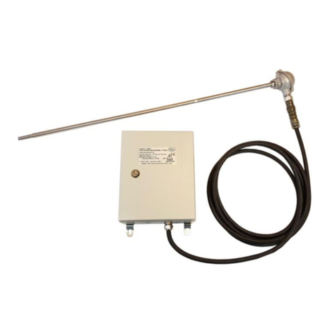
Oxygen trim control is another valuable option to achieve maximum efficiency and fuel savings. Fir-
eye’s zirconia oxygen probe has earned an international reputation for reliability and longevity. Oxy-
gen trim automatically and continuously compensates for all the variables that affect efficient
combustion. This option will give typical fuel savings of 2% and will ensure safe and efficient com-
bustion when firing fuels with varying calorific value.
Optional simultaneous firing software has been developed by Fireye which employs novel, dynamic
setpoint technology. It ensures that the correct fuel/air ratio is maintained across the firing range
when two fuels are being fired simultaneously and the ratio of one fuel to the other is maintained
correctly. A single 4 to 20mA signal varies the mix of the two fuels being fired. Oxygen trim is
needed for all simultaneous firing applications. Fuels or fuel combinations with differing and/or
varying calorific values can be accommodated. Switching between various fuel combinations
becomes a routine task.
“ComFire” communications software is an option available for the PPC 5000 electronic fuel/air ratio
controller. This powerful package gives connection to a local or remote personal computer via an
RS485 connection. Information such as setpoints, profiles and engineer’s data is displayed in tabular
and graphic form. A dynamic plant mimic shows the status of all burners on the site provided that
they have PPC 5000 controls. Burner utilization curves can be displayed as chart recorder images
and alarms with time and date stamp are also shown. “ComFire” provides non-safety critical ana-
logue and digital control of the burner from the PC. It is possible to select “burner on”, “trim on”,
“release to ignite”, “release to modulate”, “enable boiler sequencing”, lead boiler for sequencing
control and boiler setpoint. Modulation rate, boiler control setpoints and limits can also be varied
from the PC.
Sequencing software for up 10 boilers is also available allowing the operator to select any boiler as
the lead boiler. As the demand increases the burners progressively move to “high fire” leaving the
last two boilers brought “online” to “modulate”.
As the demand decreases boilers progressively move from “high fire to “modulating” and then from
“modulating to “off-line”. Three pass code levels ensure that unauthorized personnel cannot service
the burners nor change commissioning data. The unit has extensive self diagnostics with primary and
secondary level fault analysis.
PPC5000
Fuel / Air Ratio
Controller
PPC-5000
APRIL 18, 2013

2
Table of Contents
This bulletin describes the installation and commissioning of the PPC5000 fuel / air ratio controller. It may be used in conjunction with
the following other bulletins:
— Nexus NEX-1001 bulletin
— ComFire combustion analysis tool user bulletin
— Nexus / PPC5000 boiler sequencing bulletin
Description....................................................................................................................................1
Safety information.........................................................................................................................4
Installation.....................................................................................................................................5
Mounting the display.....................................................................................................................6
Circuit board removal....................................................................................................................7
Option link selection .....................................................................................................................8
Servo-motor Selection...................................................................................................................9
Wiring..........................................................................................................................................10
Operation in run mode.................................................................................................................16
Start-up sequence ........................................................................................................................19
Modulation..................................................................................................................................20
Safety shutdown (burner lockout)...............................................................................................20
The display..................................................................................................................................21
Motor adjustment ........................................................................................................................24
Feedback potentiometer ..............................................................................................................24
Control direction .........................................................................................................................24
Adjusting microswitch positions.................................................................................................24
Locking the servo-motor to the valve shaft.................................................................................25
Operation in commissioning mode .............................................................................................26
Commissioning data....................................................................................................................26
Option set mode ..........................................................................................................................27
Commission ratio mode ..............................................................................................................28
Adjust ratio mode........................................................................................................................29
Finding the software issue & unit configuration.........................................................................31
The oxygen trim option...............................................................................................................32
Oxygen probe description ...........................................................................................................32
Installation of oxygen probe........................................................................................................33
Wiring..........................................................................................................................................35
Interface to auxiliary equipment .................................................................................................37
Calibrating and servicing the oxygen probe................................................................................38
Removing the oxygen probe .......................................................................................................39
SOx, NOx, smoke, CO, AUX1, AUX2, O/P1, O/P2 ..................................................................40
Oxygen trim operation ................................................................................................................40
Commissioning oxygen trim.......................................................................................................40
Flow calculation table .................................................................................................................43

3
®
Troubleshooting.......................................................................................................................... 45
Inverter (variable speed) drives.................................................................................................. 47
System configuration.................................................................................................................. 47
Description of control method.................................................................................................... 48
Setting up the inverter for use with the 5000.............................................................................. 48
Setting up the 5000 for use with a inverter drive........................................................................ 49
Troubleshooting inverter problems............................................................................................. 50
Option parameters....................................................................................................................... 51
Option parameter selection of profiles and drives...................................................................... 72
Derivation of modulation rate..................................................................................................... 73
Faults and fault finding............................................................................................................... 74
Fault listing................................................................................................................................. 75
The engineer’s key...................................................................................................................... 79
Troubleshooting.......................................................................................................................... 84
Technical specification ............................................................................................................... 87
Oxygen probe kit ........................................................................................................................ 89
5000 Commissioning sheet......................................................................................................... 89
Option parameters....................................................................................................................... 90
Distribution board connections................................................................................................... 91
AH221250 (for use with 2 x IDB).............................................................................................. 91
AH221312 (for use with 1 x IDB & 1 x FMI)............................................................................ 92

4
SAFETY INFORMATION
WARNING: The equipment in this manual is capable of causing property damage, severe
injury or death. It is the responsibility of the owner or user to ensure that the equipment
describedhereinisinstalled,operatedandcommissionedincompliancewiththerequirements
of all national and local legislation which may prevail.
When this equipment is mounted on a burner/boiler, due regard must be given to the requirements of
that appliance.
Before attempting to install, commission or operate this equipment, all relevant sections of this
document must be read and fully understood. If in doubt about any requirements consult the
supplier. Installation, commissioning or adjusting of this product MUST be carried out by suit-
ably trained engineers or personnel qualified by training and experience.
The manufacturer of this equipment accepts no liability for any consequences resulting from the
inappropriate, negligent or incorrect installation, commissioning or adjustment of operating parame-
ters of the equipment.
This equipment MUST only be mounted on to burners as detailed in the contracted specification.
The supplier must approve any change in the specification in writing.
Control panels MUST NOT be left uncovered while power is on. If it is essential to do so while rec-
tifying faults, only personnel qualified by training and experience should be involved.
The time any covers are off must be kept to a minimum and warning notices MUST be posted.
Before attempting any work on this equipment, the electrical supplies MUST be isolated.
Safety interlocks MUST NOT be removed or over-ridden. Any faults detected MUST be corrected
before the unit is operated.
CAUTION: Some versions of this equipment contain a lithium battery.
Note: The manufacturer of this equipment has a policy of continual product improvement and
reserves the right to change the specifications of the equipment and the contents of this manual with-
out notice.
WARNING: Explosion of fire hazard can cause property damage, severe injury or death. To
prevent possible hazardous burner operation, verification of safety requirements and inter-
locks must be performed each time a control is installed on a burner.

5
®
INSTALLATION
BEFORE INSTALLING THE PPC5000 CONTROL
Wiring Base
Install the PPC5000 where the relative humidity never reaches the saturation point. The PPC5000
system is designed to operate in a maximum 80% relative humidity continuous, non-condensing
environment. Do not install the PPC5000 system where it can be subjected to vibration in excess of
0.5G continuous maximum vibration. The PPC5000 system is not a weather tight enclosure.
Wiring must comply with all applicable codes, ordinances and regulations.
1. Wiring must comply with NEC Class 1 (Line Voltage) wiring.
2. Limits and interlocks must be rated to simultaneously carry and break current to the ignition
transformer, pilot valve and main fuel valve(s).
3. Recommended wire routing of lead wires:
a. Do not run high voltage ignition transformer wires in the same conduit with any other
wires.
b. Do not route flame detector lead wires in conduit with line voltage circuits. Use separate
conduit where necessary.
4. Maximum wire lengths:
a. The maximum lead wire length is 200 ft. (61 meters) to terminal inputs (Operating limits,
interlocks, valves, etc.).
b. Modbus communications: The maximum cable length of wire is 3200 feet (1000 meters)
for RS-485.
FIGURE 1. Mounting the Control Unit
This section contains basic installation
information concerning the PPC5000 sys-
tem (controller and panel-mounted dis-
play), the servo-motors and the wiring.
The control unit is designed to be fitted
inside the burner control cabinet. The cabi-
net should have a minimum protection
level of NEMA 12 (IP40) for indoor use,
or NEMA 4 (IP54) for outdoor use.
The control unit should be mounted so that
the circuit boards within it are vertical, to
maximize cooling efficiency.
A clearance is required of a least 80mm
above and 20mm below and at the sides of
the controller enclosure.
The operating temperature range of the
equipment is 0 to 60°C.
CAUTION: Ensure that electric power is turned off. Refer to SN-100 for recommended
grounding techniques.
Be aware that power to some interlocks (operating controls, air flow switches, modulating
circuits, etc.) may be derived from sources other than what is controlling the PPC5000.
5.7” (144mm)
2.7” (70mm)
8.1”
(205
mm)
8.7”
(220
mm)
7.6”
(192
mm)
1/8” (M4) CLEAR
ALL DIMENSIONS IN INCHES (MILLIMETERS)
FRONT VIEW
UP

6
FIGURE 2. Mounting the Display
WIRING CONNECTIONS
DISPLAY CONTROLLER PPC5000
1 = 5v PA8
2 = KEY RETURN PA9
3 = DATA PA10
4 = CLOCK PA11
5 = STROBE PB3
6 = GROUND PA15
1 5/8” (40mm)
4 HOLES (M4 CLEAR)
PANEL CUT-OUT
3 7/16” (87mm)
4 1/4” (108mm)
3 26/32” (97mm)
4 1/8” (105mm)
4 27/32” (123mm so.)
PANEL FRONT
The display should be mounted on the
front of the burner cabinet, or similar
accessible location, as close to the con-
troller as is practical.
Refer to factory for cable recommenda-
tions if the display’s cable length needs to
be extended.
It extends for [40mm]/[1.6in] behind the
panel, and [5mm]/0.2in] in front of the
panel.
The maximum allowable panel thickness is
[7mm]/[0.3in].

7
®
Circuit Board Removal
Please refer to the exploded unit drawing below.
5. Disconnect the unit’s power supply.
6. Undo the four screws and remove the grey plastic lid to expose the connectors.
7. Remove all the connectors.
8. Undo the four hexagonal pillars, and lift away the retainer frame.
9. Carefully remove the distribution board.
10. Each of the daughter boards can now be removed as required by pulling on the edge of the PCB
(do not pull the connector strips).

8
Option Link Selection
The unit has a number of option selection links, located on various boards. The function and settings
are marked along side each link. These links must be set to the correct position before power is
applied.
Power Supply Voltage
The 5000 control system must be set for the correct supply voltage.
The supply voltage is selected via a link arrangement on the power supply board. The possible sup-
ply voltages are tabulated below, together with the necessary fuse rating.
In order to set these links and fit the correct supply fuse, the power supply board must be removed
(see Circuit board removal).
Boiler Pressure and Temperature Sensor Type and Supply
If a boiler pressure/temperature sensor or modulation potentiometer is used, the links LK9 and LK10
on the power supply board must be set to suit the type of sensor. For example:
For a 4-20mA loop-power sensor, choose a +20V supply with current (I) input.
For a 0-5V modulation potentiometer, choose a +5V supply with voltage (V) input
Ensure that option parameter 3.2 is set to match this jumper position.
Potentiometer Supply Voltage
The 5000 can either supply +5v or +15v DC to the potentiometers.
If the potentiometer moves over its entire 270º range for 90º of servo-motor travel, select a +5v
supply.
If the potentiometer is a 340º type but only moves over 90º of its range for 90º of servo-motor travel,
select a +15v supply.
For the basic drive board, a single jumper link (LK1) is fitted which determines the supply voltage
for all four feedback potentiometers connected to the board. The position for each supply voltage is
printed on the circuit board adjacent to the jumper.
For the isolated drive board, two jumper links are fitted which determine the supply to each of the
two feedback potentiometers connected to the board. The positions for each supply voltage are
printed on the board next to the link. LK1 selects the supply voltage for feedback potentiometer 1.
In order to set the feedback potentiometer supply jumpers, the boards must be removed from the
enclosure. For details of how to do this, see Circuit board removal.
SUPPLY VOLTAGE (V) LINKS REQUIRED FUSE RATING (mA)
110 LK1 AND LK3 315 ANTI-SURGE
120 LK4 AND LK6 315 ANTI-SURGE
220 LK2 AND PARK 160 ANTI-SURGE
240 LK5 AND PARK 160 ANTI-SURGE
POTENTIOMETER TYPE SUPPLY VOLTAGE
MINIMUM
POTENTIOMETER VALUE
(Ohms)
MAXIMUM
POTENTIOMETER VALUE
(Ohms)
270° with full travel 5V 1K 5K
340° with 90° travel 15V 3K 15K

9
®
RS485 TERM (RS485 serial communications termination resistor)
The position of this link is important only
if the RS485 serial communications are to
be used. The two units at the end of the
communications bus should have this link
set to the IN position. All other units
should have the link set to the OUT posi-
tion. If only two units are on the communications bus, set the links on both units to the IN position.
This link is LK1 on the burner interface board.
SERVO-MOTOR SELECTION
Motor Requirements
Since the servo-motors are not always supplied as part of the 5000 system, a few guidelines are
useful when selecting suitable motors other than those supplied by Fireye.
• All servo-motors must be of the same operating voltage, not exceeding 250V rms / 50V rms
depending on board type.
• All motors must be AC
• The servo-motor current must not exceed 150mA rms / 750mA rms depending on board type.
• If the motor voltage is lower than the mains supply voltage then a suitable power supply (such
as a transformer) must be provided
• The motor supply to the 5000 must be protected with a suitable fuse for the motors being used.
The fuse must not exceed 3A to ensure that damage to the control unit does not occur
• The servo-motor time for 90° movement must not be less than 10 seconds or more than 60 sec-
onds
• All servo-motors must have internal limit switches fitted which are adjusted to prevent exces-
sive rotation
• All servo-motors must be able to drive the load imposed on them
• All servo-motors must have suitable protection for the burner environment (for example, IP65
for applications exposed to the weather).
If in any doubt about a particular servo-motor’s suitability, seek confirmation from your equip-
ment supplier, who have a list of suitable motors.
Potentiometer requirements
All servo-motor potentiometers should be good quality plastic film types, with high resolution.
Depending on the supply voltage, a minimum resistance is allowed for the feedback potentiometers
to prevent excessive current consumption. See section 1 - Potentiometer supply voltage on page 8 for
details.
The potentiometer must be securely fixed to the output shaft of the gearbox in such a way as to give
accurate indication of the shaft position under all conditions and at all times.
IN
OUT
RS485
TERM
IN
OUT
RS485
TERM
IN
OUT
RS485
TERM
PC

10
Wiring
WARNING: Wiring Installation must be carried outby acompetent electrician andis subject
to I.E.E. wiring regulations (BS 7671:1992) and/or local standards.
Hazardous voltages must be isolated before service work is carried out.
The clamping bar on the control unit performs only an earth function and does not provide strain
relief. Secure all cables carried in conduit at both ends using a suitable anchorage method in the cab-
inet.
If the mains power is known to be noisy or suffer from occasional brown-outs or black-outs then a
correctly rated (20w) un-interruptible power supply (UPS) should be used to ensure a clean continu-
ous mains power supply to the 5000 controller. This must be located as close as possible to the unit.
To comply with EMC requirements, wire the control unit using the specified cable sizes and shield
connections. Clamp all signal cable shields to ground using the clamping bar provided on the control
unit. Connect all cable shields to ground at the control unit end only, with the exception of the cables
that connect the display and pressure sensors. Use Belden 8735 or equivalent.
The unit case and PA6 must be connected to Ground.
Using the Cable Clamp
A clamping bar is provided on the control
unit for termination of cable screens
where necessary.
The cable should be prepared by cutting
around the outer sleeve, taking care not to
damage the screen (1).
Pull the sleeving apart to expose 1/3”
(8mm) of the screen (2).
Place the exposed length of screen under
the clamp bar and tighten the screws (3).
8mm
(1)
(2)
(3)

11
®
LIVE and NEUTRAL Supply
The LIVE and NEUTRAL supplies must be con-
nected using multi-strand single core PVC insu-
lated 16/0.2mm wire. The live connection should
be fused with a maximum rating of 3A.
The NEUTRAL connection for PC19 must be
wired to PA4. The NEUTRAL for PC19 must not
come from anywhere else.
Interface to Burner Controller Units
WARNING: Although the 5000 system has an optional software controlled postpurge this
MUST NOT be used to replace the pre-purge as dictated by the chosen burner controller.
Please note whatever burner controller is being used that the PPC 5000 must be wired so
that a safety shutdown will switch off the burner.
Since many different burner controller units can be
used with this system, it is only intended that guid-
ance on interconnection be given in this bulletin.
Specific information for interconnection to
approved "burner controllers" should be obtained
from the manufacturer. Alternatively specific infor-
mation should be obtained by reference to the sup-
plier of this equipment.
These connections must be wired using single con-
ductor TEW, AWM or MTW within the cabinet.
Conductors to be pulled through conduit should be
THHN or TFFN.
Maximum wiring size is 16 AWG.
Fuel, auto/man (H/A), up, down, aux 1 and aux 2 inputs
These inputs must be connected using multi-strand single core PVC insulated 16/0.2mm wire. Note
that these inputs expect high voltage mains signals with the same phase as the mains supply on PA1.
The three fuel selection inputs are used to determine which profile the unit selects. Each profile can
fire any combination of the three different fuels.
LIVE PA 1
NEUTRAL PA3
NEUTRAL PA4
LIVE
NEUTRAL
MAX 3A
NEUTRAL
TO PC19
PC19
PC17
PC16
PC15
PC14
PC13
ON / OFF PC12
HI / LO PC11
PC10
PC9
PC8
PURGE PC7
IGN PC6
COMM PC5
CONTROL TRIAC PC4
CONTROL TRIAC PC3
SAFETY RELAY PC2
SAFETY RELAY PC1
BURNER CONTROL SIGNALS

12
The two auxiliary inputs can be configured via option parameters to provide / override various status
inputs such as fault mute, burner on etc.
If the hand/auto (H/A) input is off, the UP and DN inputs will have no effect, and the unit will mod-
ulate automatically.
If the hand/auto (H/A) input is on, the UP input will cause the modulation rate to increase
if it is energized, and the DN input will cause the modulation rate to decrease if it is
energized.
Motor Up/Down Outputs and Feedback Potentiometer Inputs
The motor up/down out-
puts should be connected
using single conductor
TEW, AWM or MTW
within the cabinet. Conduc-
tors to be pulled through
conduit should be THHN
or TFFN. Maximum wiring
size is 16 AWG. The con-
nections to the motor
should be made via its
switched inputs, so that the
internal micro switches
prevent the motor being
damaged if it is driven to
either end of its travel.
Motor feedback potentiom-
eter cabling must be overall
shielded 3-conductor PVC
insulated Belden 8735 or
similar. Since this cable may be run in conduit with the motor drive wiring, its voltage rating must
exceed the maximum voltage carried by any other cable in the same conduit.
Connect the shield with the use of the clamping bar.
Make all connections at the servo-motor first. Incorrect connection may damage or destroy the
motor potentiometer.
PROFILE 1
INPUT
(PC13)
OFF
PROFILE 2
INPUT
(PC14)
OFF
PROFILE 4
INPUT
(PC17)
OFF
PROFILE
SELECTED
NONE
BURNER OFF
ON OFF OFF 1
OFF ON OFF 2
ON ON OFF 3
OFF OFF ON 4
ON OFF ON 5
OFF ON ON 6
ON ON ON 7
M
LINE/MOTOR
CABLE CLAMP
NEUTRAL/MOTOR
COMMON
SUPPLY
MOTOR COM PE 1
MOTOR UP PE 3/5/8/10
MOTOR DN PE 2/4/7/9
POT SUPPLY PD 4/10/13/18
FEEDBACK PD 3/9/12/17
POT GND PD 2/8/11/16

13
®
Pressure/Temperature Sensor Input
The pressure/temperature cabling
must be overall shielded 3-conduc-
tor Belden 8735 or similar. Since
this cable may be run in conduit
with high voltage wiring, its voltage
rating must exceed the maximum
voltage carried by any other cable
in the same conduit.
The input is suitable for use with 0-5V
or 4-20mA signals (externally or inter-
nally powered), the PXMS-XXX steam
pressure sensor, or a three wire resis-
tance thermometer.
Refer to the option links section for
details on setting the correct voltage
and input type.
Connect the cable shield to the controller with the use of the clamping bar.
Make all connections at the sensor/transmitter first.
SENSOR SUPPLY PA16
SENSOR IN PA17
SENSOR GND PA18
CABLE
CLAMP
Fireye PXMS-XXX
SENSOR
+ -
OR EXT. SELF-
POWERED
4-20mA /0-5V
5/20V
+
-
CABLE
CLAMP
SENSOR GND PA18
SENSE RTD PA19
RTD SUPPLY PA20
3 – WIRE
RESISTANCE
THERMOMETER

14
RS485 / RS232
The RS485 cabling must be overall shielded 3-conductor Belden 8735 or similar. Terminate the
shield at one unit only using the cable clamp provided.
For details on connecting NEXUS integrated burner controllers, PPC5000 fuel/air ratio controllers
and a PC onto the communications bus, refer to bulletin NEX-1501 (ComFire combustion analysis
tool) or NEX-SO (boiler sequencing).
Controlled Shutdown Triac and Safety Shutdown Relay
The controlled shutdown triac should be wired into the ”stat" circuit to switch the burner on/off as
the temperature/pressure reaches the limit condition.
The safety shutdown relay must be wired to ensure that the burner is immediately switched off if the
relay opens, to prevent any hazardous condition occurring. See recommended interface wiring for
details of how this is accomplished via connection to burner controllers.
PURGE and IGN Outputs
The PURGE (PC7) terminal will be connected to the COM (PC5) terminal when the 5000 is at purge
position.
The IGN (PC6) terminal will be connected to the COM (PC5) terminal when the 5000 is at the igni-
tion position.
See Appendix for details of how these terminals should be interfaced to burner controllers.
HI/LO Input
This input is active during start-up only.
When this terminal is connected to mains potential, the 5000 will move to purge position. When this
terminal is not connected to mains potential, the unit will move to ignition position.
See Interface to Burner Control Units section on page 11 for details of how these terminals should be
interfaced to burner controllers.
Alarm Relay
This is provided to add an external siren or
lamp for indication of a unit fault or flue
gas alarm limit. The alarm relay must not
be used to shutdown the burner. This
function is provided by the safety shut-
down relay.
RS485 COMMS
BUS
To PC /
modem (via
converter) or
Nexus /
PPC5000
+
GND
-
CLAMP
Rx
Tx
GND
CLAMP
RS232 to
local PC
or modem
+
GND
-
CLAMP
Rx
Tx
GND
CLAMP
+
GND
-
CLAMP
Rx
Tx
GND
CLAMP
CLOSED IN ALARM PB12
OPEN IN ALARM PB13
COMMON PB14
LIVE SUPPLY
Siren or
Lamp
NEUTRAL

15
®
Digital Outputs
The digital outputs are set-up via
option parameters 16.1, 16.2, & 16.3.
The outputs are intended to drive exter-
nal relays, as shown here for output 2.
Remote Setpoint
The remote setpoint input is available
as a 4-20mA current input. It con-
nects to terminal PQ2, labeled “AUX
MOD I/P”. For details relating to
zero and span adjustment see Option
Parameter section. See option 3.3.
Final Checks
Before applying power, make the following checks:
• The unit is set for the correct line supply voltage.
• All other link positions are correct.
• All fuses within the unit are intact and of the correct value.
• All wiring and connections have been made according to the specifications detailed in this sec-
tion.
• The Feedback Potentiometer is wired correctly. Terminal 6 on the servo-motor MUST be wired
to PD 3/9/12/17 depending on the motor mapping. See option 20.
TO
EXTERNAL
CIRCUITS
USE ONLY MANUFACTURER
APPROVED RELAYS
+12V PB7
DIGITAL OUTPUT 1 PB8
DIGITAL OUTPUT 2 PB9
DIGITAL OUTPUT 3 PB10
+20V PQ1
AUX MOD I/P PQ2
0V PQ6
CABLE
CLAMP
LOOP POWERED
4-20mA SENSOR
+ -
OR EXT. SELF-
POWERED
4-20mA
20V
+
-

16
Operation in Run Mode
Start-up Sequence
When a fuel selection is made, and the ‘burner select’ signal is given, the burner will start up. The
control unit will run through the sequence described below.
No Name Description
0, 1 INITIALIZE The unit has just been powered up. If there are no faults,
the unit will immediately proceed to status 3.
Otherwise, it jumps to status 2.
2 SAFETY SHUTDOWN There is a safety critical fault present which is preventing
the burner from being fired safely.
All drives (motors and inverters) are driven to their close
(P0) positions. The safety shutdown output (PC1-2) and
controlled shutdown output (PC3-4) are both open circuit.
See Faults and fault finding section.
3 BURNER OFF The safety shutdown output (PC1-2) is closed but the
controlled shutdown output (PC3-4) is open, preventing
the burner from firing.
The unit will proceed to status 4 if:
— Burner select input (PC12) is off (EK5 = 0)
— High/low initiate input (PC11) is off (EK4 = 0)
—þMeasured value below low control limit (EK14 = 1)
If the burner select input (PC12) is on for more than 3
seconds, the unit will go to status 2 with F56.
All drives (motors and inverters) are driven to their close
(P0) positions.
4 WAIT FOR PURGE The safety shutdown output (PC1-2), the controlled shut
down
output (PC3-4) and the ignition prove output are all closed.
The unit will proceed to status 5 if:
— A valid profile is selected using PC13, 14 and/or 17
— Burner select input (PC12) is on (EK5 = 1)
— High/low initiate input (PC11) is on (EK4 = 0)
— All drives (motors and inverters) are driven to their close
(P0) positions.
5 PROVE CLOSE The safety shutdown output (PC1-2), the controlled shut
down
(P0) POSITIONS output (PC3-4) and the ignition prove output are all closed.
All selected motors are driven fully down, and 4mA is output
to the inverters.
The unit will proceed to status 6 if:
— All drives have stopped moving and match their close
(P0) positions to within ±5° (or ±55 for inverters).
— Burner select input (PC12) is on (EK5 = 1)
— High/low initiate input (PC11) is on (EK4 = 1)
— The inverter stop time (option parameter 22.4) has expired
If the burner select (PC12) or high/low initiate (PC11) inputs
are turned off or the profile selection (PC13, 14 and/or 17) is
changed, the unit returns to status 3.

17
®
If any of the measured drive positions do not match P0,
the unit will change to status 2 with a drive positioning fault.
6 PROVE PURGE The safety shutdown output (PC1-2) and the controlled
(P1) POSITIONS shutdown output (PC3-4) are both closed.
All selected motors are driven fully up, and 20mA is
output to the inverters.
The unit will proceed to status 7 if:
— All drives have stopped moving and match their purge
(P1) positions to within ±5° (or ±55 for inverters).
— Burner select input (PC12) is on (EK5 = 1)
— High/low initiate input (PC11) is on (EK4 = 1)
If the burner select (PC12) or high/low initiate (PC11) inputs
are turned off or the profile selection (PC13, 14 and/or 17) is
changed, the unit returns to status 3 (or status 13 if a post
purge has been selected using option parameter 09.1).
If any of the measured drive positions do not match P1, the
unit will change to status 2 with a drive positioning fault.
7PRE-PURGE The safety shutdown output (PC1-2), the controlled
(CLOSING FUEL shutdown output (PC3-4) and the purge prove output (PC5-7)
DRIVES) are all closed.
All selected air and option drives are driven to their purge
(P1) positions.
All selected fuel drives are driven to their close (P0)
positions.
The unit will proceed to status 8 when all fuel drives have
stopped moving.
The high/low initiate input (PC11) is ignored.
If the burner select input (PC12) is turned off or the profile
selection (PC13, 14 and/or 17) is changed, the unit returns to
status 3 (or status 13 if a post purge has been selected using
option parameter 09.1).
If the measured air or option drive positions do not match P1,
the unit will change to status 2 with a drive positioning fault.
8PRE-PURGE The safety shutdown output (PC1-2), the controlled
shutdown output (PC3-4) and the purge prove output (PC5-7)
are all closed.
All selected air and option drives are driven to their purge
(P1) positions.
All selected fuel drives are driven to their close (P0)
positions.
The unit will proceed to status 9 when the high/low initiate
input (PC11) is turned off.
If the burner select input (PC12) is turned off or the profile
selection (PC13, 14 and/or 17) is changed, the unit returns to
status 3 (or status 13 if a post purge has been selected using
option parameter 09.1).
If the measured air or option drive positions do not match P1,
the unit will change to status 2 with a drive positioning fault.
9 MOVING TO THE The safety shutdown output (PC1-2) and the controlled
IGNITION shutdown output (PC3-4) are both closed.

18
POSITION All selected drives (motors and inverters) are driven to their
ignition (P2) positions.
The unit will proceed to status 10 if:
— The drives have stopped moving.
— If selected, a ‘release to ignite’ signal is received via serial
comms or an auxiliary input (see option parameters 15.1 and
15.2)
If the burner select input (PC12) is turned off, the profile
selection (PC13, 14 and/or 17) is changed or the high/low
initiate input (PC11) is on, the unit returns to status 3
(or status 13 if a post purge has been selected using option
parameter 09.1).
10 IGNITION The safety shutdown output (PC1-2), the controlled shutdown
output (PC3-4) and the ignition prove output (PC5-6) are
all closed.
All selected drives (motors and inverters) are driven to their
ignition (P2) positions.
The unit will proceed to status 11 when the ignition time has
expired (see option parameter 08.1)
If the burner select input (PC12) is turned off, the profile
selection (PC13, 14 and/or 17) is changed or the high/low
initiate input (PC11) is on, the unit returns to status 3
(or status 13 if a post purge has been selected using option
parameter 09.1).
If the measured drive positions do not match P2, the unit will
change to status 2 with a drive positioning fault.
11 MOVING TO THE The safety shutdown output (PC1-2) and the controlled
LOW FIRE shutdown output (PC3-4) are both closed.
POSITION All selected drives (motors and inverters) are driven to their
low fire (P3) positions.
The unit will proceed to status 12 if:
— The drives have stopped moving.
— The low fire hold time has expired (see option parameter
8.2)
— If selected, a ‘release to modulate’ signal is received via
serial comms or an auxiliary input (see option parameters
15.1 and 15.2)
If the burner select input (PC12) is turned off or the profile
selection (PC13, 14 and/or 17) is changed the unit returns to
status 3 (or status 13 if a post purge has been selected using
option parameter 09.1).
The high/low initiate input (PC11) is ignored.
If the drive positions are outside the ignition and low fire
positions, the unit will change to status 2 with a drive
positioning fault.
12 MODULATION The unit modulates all selected drives in ratio to the required
modulation rate. Trim will be applied after the transport
delay has expired (if selected). The modulation may be
limited by the oxygen trim function (see EK77 & EK78).
If the burner select input (PC12) is turned off, the profile
selection (PC13, 14 and/or 17) is changed or the measured

19
®
value exceeds the high control limit, the unit returns to status
3 (or status 13 if a post purge has been selected using option
parameter 09.1).
The high/low initiate input (PC11) is ignored.
If any selected drive deviates from its profile setpoint, the
unit will change to status 2 with a drive positioning fault.
13 MOVING TO POST The safety shutdown output (PC1-2) is closed but the
PURGE controlled shutdown output (PC3-4) is open, preventing
the burner from firing.
All selected air and option drives are driven to their purge
(P1) positions.
All fuel drives are driven to their close (P0) positions.
The unit will proceed to status 14 when the air and option
drives have stopped moving.
The burner select input (PC12), fuel select inputs (PC13, 14
and 17) and the high/low initiate input (PC11) are ignored.
14 POST PURGE The safety shutdown output (PC1-2) and the controlled
shutdown output (PC3-4) are both closed.
All selected air and option drives are driven to their purge
(P1) positions.
All fuel drives are driven to their close (P0) positions.
The unit will return to status 3 when the post purge time has
expired (see option parameter 09.1).
The burner select input (PC12), fuel select inputs (PC13, 14
and 17) and the high/low initiate input (PC11) are ignored.
If the measured air or option drive positions do not match P1,
the unit will change to status 2 with a drive positioning fault.
Startup sequence
Safety shutdown O/P (PC1-2)
Controlled shutdown O/P (PC 3-4)
Ignition prove output (PC 5-6)
Purge prove output (PC 5-7)
HI / LO initiateinput (PC 11)
Burner on input (PC 12)
Fuel drive(s)
A
ir and option drive(s)
- Energized\active - Don't care
0/1 2 3 4 5 6 7 8 9 10 11 12 13 14
Fuel select inputs (PC13, 14, 17)

20
Modulation
During stage 12 (modulation), the unit will position the fuel and air motors as programmed for the
profile selected.
In auto modulation mode, the system will modulate as necessary to either track the input or maintain
the pressure/temperature of the boiler at the entered setpoint (See Option parameters section). If
boiler sequencing is enabled and active, the unit will start, stop and modulate according to instruc-
tions issued from the unit controlling the lead boiler.
In manual modulation mode, the system will either modulate in response to the keyboard up/down
keys or the external up/down signals.
Safety Shutdown (Burner Lockout)
A safety shutdown will occur under the following conditions:
• In stages 5, 6, 7, 8, 10, 11, 12, or 14, if a drive is not in the correct position.
• During stage 6, a drive speed has been measured to be outside the allowable range.
• During modulation (stage 12), an oxygen trim limit has been reached, and this has been config-
ured to shut the burner down (see option parameter 39.0).
• In any stage, if an internal or external fault not previously mentioned occurs which may affect
the safe operation of the burner.
The display is a 2 line 20 character per line dot matrix vacuum fluorescent unit allowing the use of
plain text messages for most display parameters. The display must be fitted to allow commissioning
of the system but once commissioning has been completed, the display may be removed, providing
either the control unit lamps and external switches and/or lamps are fitted for fault indication and
reset.
Table of contents
Other Fireye Controllers manuals
Fireye
Fireye BurnerPRO BP110 User manual

Fireye
Fireye PPC6000 Series Operating instructions
Fireye
Fireye NEXUS NX6100 series User manual
Fireye
Fireye BurnerPRO BP110 User manual
Fireye
Fireye D10 Series User manual
Fireye
Fireye PPC6000 Series User manual
Fireye
Fireye FLAME-MONITOR E110 User manual
Fireye
Fireye MicroM Series User manual

Fireye
Fireye PPC6000 Series Manual
Fireye
Fireye PPC4000 SERIES User manual
