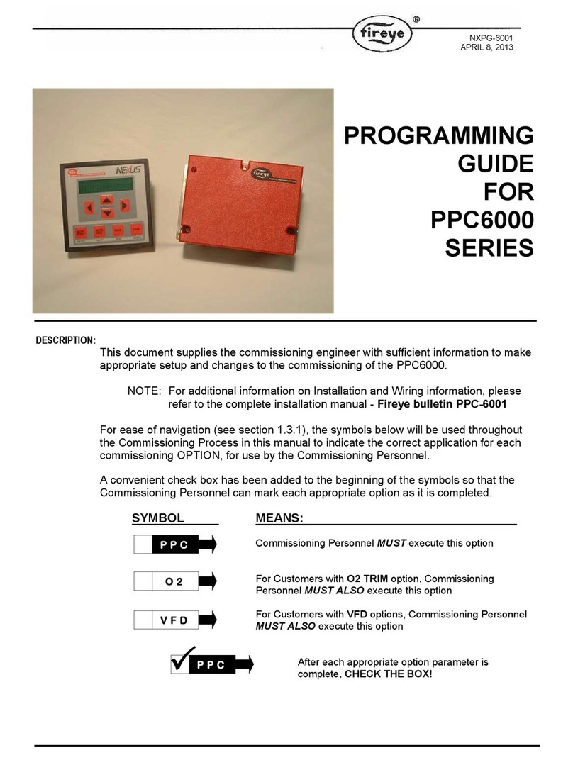
Fireye PPC6000 Series Manual

OPERATOR’S
GUIDE
FOR
PPC6000
SERIES
DESCRIPTION:
This document supplies the owner/operator with sufficient information to make
appropriate changes to operating parameters associated with normal boiler plant
needs. Items such as system setpoint adjustments e.g. temperature, pressure, PID
adjustments and alarm corrective action and adjustments.
The following items are covered in this manual:
1 Introduction _____________________________________________________2
2 General _________________________________________________________2
3 Password _______________________________________________________2
4 Adjusting Cut IN and Cut OUT_____________________________________3
5 Manual Modulation ______________________________________________4
6 Resetting the Control _____________________________________________4
7 Fault and Fault Finding __________________________________________11
8 Fault subsets ___________________________________________________11
9 Fault listing ____________________________________________________12
10 PID Tutorial____________________________________________________18
11 The Startup / Shutdown Stages ____________________________________19
NXOG-6001
MARCH 9, 2007

2
1 Introduction
As an operator there are generally only a few items of interest as far as operating the Nexus PPC6000. They
are:
xSetting the system’s operating pressure or temperature.
xAdjusting the cut in or cut out value.
xManually modulating the boiler.
xResetting the control after a safety shut down.
xFinding the Fault that caused the shut down.
All of the other options and adjustments should be done by the combustion technician, as changes to certain parameters could result in an
unsafe operating mode.
2 General
The Nexus display and keypad allows the operator (or combustion technician) access to all set points and
option parameters for commissioning and operating the Nexus PPC6000. The keys are labeled with their
primary function on the key, their secondary function under the key. E.g.: COM/ENTER.
Several levels of passwords protect the integrity of the control. These passwords are numbers entered by
using the up/down arrow keys after pressing the COM (commissioning) key. To enter the password start by
pressing the COM (commissioning) key. You will have 30 seconds to reach the password value and press the
ENTER (COM) key.
3 Password
The only password an operator should require is the “site Passcode.” This can be set as a number from 0-
999. The factory default number is 154. The site Passcode can be changed if desired, however, this requires
the use of a higher-level Passcode.
Warning: Should the Passcode be changed and forgotten, the PPC6000 will have to be reprogrammed
by using the higher-level Passcode. Until then, no adjustments are possible.
Operating Pressure – PID (set point) 1 or (2)*
* NOTE: ( ) Parentheses indicate set point 2 option parameter. E.g. Day/night.
To set or adjust the boiler’s operating pressure follow steps 1 thru 7:
1. Press the COM key.
2. Use the UP key to raise the value to 154 (or new Site Passcode, if changed).
3. Press the ENTER key. This is the same key as COM.
4. If the display shows the angular positions of the servomotors, press the MODE key to change to
option parameters. Using the up or down key move to OPTION 21.1 (22.1). This is the control
value the Nexus will modulate the burner to maintain.
5. Use the left or right arrow key to move the cursor to the lower portion of the display, then using the
up/down arrow key change the setting.
6. Press the ENTER key to accept the new set point.
7. To exit and return to the normal run mode, press the RUN key followed by the ENTER key.

3
Note: The next time you enter the site password you will return to the last option selected.
4 Adjusting Cut IN and Cut OUT
Follow steps 1 through 3 above.
4. If the display shows the angular positions of the servomotors, press the MODE key to change to
option parameters. Using the up or down key, move to OPTION 21.6 (22.6) for Cut In or 21.7
(22.7) for Cut Out. This is the control value the Nexus will start/stop the burner after reaching the
cut in/out value. This value is a differential value when option parameter 21.5 (22.5) is set at 2.
That is, it is subtracted/added from/to the operating set point. Once set, this value will follow any
change in the set point programmed in option 21.1 (22.1). These values are actual values if 21.5
(22.5) are set to 1. (see table below)
Option parameter
21.5 (22.5) value
Meaning
0No limits. The burner will run until another method is used to switch
it off.
1Absolute limit. The values entered in option parameters 21.6
(22.6) and 21.7 (22.7) are the actual limit values.
2Deviation limit. The values entered in option parameters 21.6
(22.6) and 21.7 (22.7) represent a deviation (i.e. offset) from the
setpoint 1 control value. This means that if the setpoint control
value is changed, the limits are automatically changed
correspondingly.
5. Use the left or right arrow key to move the cursor to the lower portion of the display then - using
the up/down arrow key, change the setting.
6. Press the ENTER key to accept the new set point.
7. To exit and return to the normal run mode press the RUN key followed by the ENTER key. See
two examples below:
Deviation Example:
Opt 21.1 (22.1)* ...............set to............... 100 psi
Opt 21.5 ...........................set to................... 2
Opt 21.6 (22.6)* ...............set to................. 10
Opt 21.7 (22.7)* ...............set to................. 10
Cut Out ..................................................... 110 psi
Set Point ................................................... 100 psi
Cut In .......................................................... 90 psi
New Set Point 60 psi
Cut Out ....................................................... 70 psi
Set Point ..................................................... 60 psi
Cut In .......................................................... 50 psi

4
Absolute Example:
Opt 21.1 (22.1)* .............. set to ............... 100 psi
Opt 21.5 .......................... set to ................... 1
Opt 21.6 (22.6)* .............. set to ............... 110
Opt 21.7 (22.7)* .............. set to ................. 90
Cut Out............................. ........................ 110 psi
Set Point........................... ........................ 100 psi
Cut In................................ .......................... 90 psi
New Set Point 60 psi
Cut Out............................. ........................ 110 psi
Set Point........................... .......................... 60 psi
Cut In................................ .......................... 90 psi
NOTE: NEW Cut In and Cut Out values may need
to be entered to achieve desired results.
5 Manual Modulation
Pressing AUTO/MAN key toggles the burner in and out of manual or automatic modulation. To place the
boiler in manual from automatic no password is required.
1. Press the AUTO/MAN key
2. Use the up/down arrow keys to set the firing rate.
3. Press the AUTO/MAN key again to place in automatic
Note: The firing rate will be shown on the display. This function can be disabled via option
parameter 1.1. To do so requires the suppliers (highest) passcode.
6 Resetting the Control
To reset the Nexus, the MUTE/RESET key will have to be pressed and held for three seconds to first silence
(mute) the alarm and then a second press for three seconds to clear the fault. A prolonged key press will do
both.
If for some reason the Nexus detects a fault, the cause of the fault will be displayed if still present. If not
displayed, pressing the ENGINEERS key once will reveal the fault, a second press will reveal the fault and
subset in the upper right hand corner. The ENGINEERS key is hidden behind the Fireyelogo on the display.
Pressing the logo will show the EK # to the right of which will be the fault # and any subset. Using the
up/down arrow keys scrolls through the EK #’s to view other information.

5
Engineer’s key parameter list
No. Name Description
EK1 Low Voltage Digital Input 1 (PA5–PA11) Shows the state of each input.
EK2 Low Voltage Digital Input 2 (PA6–PA11) Where :
EK3 Low Voltage Digital Input 3 (PA7–PA11) 0 = OFF (Open circuit)
EK4 Low Voltage Digital Input 4 (PA8–PA11) 1 = ON
EK5 Low Voltage ‘HIGH’ input (PA9–PA11)
EK6 Low Voltage ‘AUTO input (P10–PA11)
EK11 Profile 1 Select – Line Voltage (PE9)
EK12 Profile 2 Select – Line Voltage (PE10)
EK13 Profile 3 Select – Line Voltage (PE11)
EK14 Profile 4 Select – Line Voltage (PE12)
EK16 Warming limit 0 - Measured value above warming limit, burner
free to modulate.
1 - Measured value below warming limit, burner
held at low fire if the control is in auto or
sequencing mode.
EK18 Boiler status 0 - Burner will not fire because the temperature /
pressure measured value has exceeded the high
control value.
1 - Burner will fire because the temperature /
pressure measured value has fallen below the
low control value.
EK19 Confirm to adjust 0 - Control not in commission mode or control is
in commission mode and drives moving to
setpoints.
1 - Control in commission mode and drives may
be adjusted using the UP/DOWN keys.
EK20 Drive moved 0 - Control not in commission mode or control is
in commission mode and drives have not been
moved using the UP/DOWN keys.
1 - Control in commission mode and drives have
been moved using the UP/DOWN keys.

6
No. Name Description
EK21 Positions proved 0 - Drives have stopped moving, ready for
position prove test.
1 - Ready for position prove test but drives still
moving.
EK22 Fault alarm 0 – No un-muted alarms (faults) present.
+1 - Un-muted fault alarm present (prefix : F)
+2 - Un-muted limit alarm present (prefix : L)
+4 – Un-muted flue-monitoring alarm present
(faults 50 to 59).
EK23 Oxygen Trim Enable 0 – Oxygen trim off or not working.
1 – Oxygen trim on and working.
EK25 CAN_TX Failures A count of the number of times the can bus
controller has failed to send a message since
power-up. This should be zero unless there has
been a problem.
EK26 Commission status Current commissioning mode, where :
0 - Normal run mode.
1 - Adjust ratio mode.
2 - Commission ratio mode.
EK27 Commission setpoint The current setpoint being commissioned.
0 - Closed setpoint.
1 - Purge setpoint.
2 - Ignition setpoint.
3 - Low fire setpoint.
4 - 24 - profile setpoints
EK28 Commission Setpoints entered The number of setpoints that have been
successfully entered during this commission ratio
session.
EK29 Modulation rate (%) The current modulation rate of the burner.
0 = Low Fire
100 = High fire
EK30 Burner Status Status of the start-up sequence. See section 4.2
of Fireye Bulletin PPC-6001
EK31 Fuel Profile Selected The currently selected fuel profile.

7
No. Name Description
EK32 Number of commission setpoints The number of setpoints entered in the current
commission ratio session :
0 - No setpoints entered.
1 - Close setpoint only.
2 - Close and purge setpoints.
3 - Close, purge and ignition.
4 - 24 - profile setpoints.
EK33 Modulation mode The current modulation mode :
0 - Auto mode.
1 - Manual from external input.
2 - Manual from keyboard.
3 - Boiler sequencing control.
4 - Low fire hold.
EK36 Nearest setpoint The number of the profile setpoint which is
nearest to the current modulation position.
EK37 Voltage reference error (V) The error between the measured voltage
reference and the calibrated value.
0.12 is the limit. The displayed value shows volts
NOTE: If value goes to 0.13, F19 will be
generated.
EK38 Boiler Sequencing Status Currently unused.
EK39 Fuel Swap Status Currently unused.
EK40 Shutdown setpoint The nearest setpoint (EK36) when the burner
last locked out.
EK42 Adjust ratio counter The number of times adjust ratio mode has been
used.
EK43 Commission ratio counter The number of times commission ratio mode has
been used.
EK44 Oxygen measured value The current flue oxygen value as measured by
the FIREYE probe (if fitted).

8
No. Name Description
EK45 Oxygen probe status +1 - Internal fault.
+2 - Internal fault.
+4 - Heater fault. Causes F50.
+8 - Cell temperature out of range.
+16 - Cell millivolts out of range.
+32 - CANbus error.
+64 - Probe calibrating in reference gas. See
option parameter 30.6.
+128 - Probe calibrating in air. See option
parameter 30.6.
EK46 Oxygen trim status 0 - O2trim working, or
+1 – no oxygen interface connected.
+2 – no oxygen probe serial number entered,
or option 30.5 not 1, or option 30.8 not 0
or trim not selected via aux input
or trim not selected via serial comms
+4 – O2setpoints or flow values incorrect
+8 - Option 30.6 not 0
+16- Not modulating
+32- In commission mode
+64- Probe faulty (see EK45)
EK47 Oxygen setpoint (%) Current oxygen setpoint. This is only available if
trim is enabled and working.
EK48 Excess air (%) Excess combustion air at the current firing
position.
EK49 Oxygen error (%) Error between O2measured value and O2
setpoint.
EK50 Trim deviation (% flow) Deviation in air flow imposed by trim (-25 to
+25%)
EK55 Main PCB issue The issue number of the main circuit board.
EK57 CPU serial number (low 3 digits)
EK58 CPU serial number (low 3 digits)
The 6 digit CPU board serial number. The serial
number is displayed in 2 blocks of 3 digits.

9
No. Name Description
EK59 Digital (relay) outputs on. Represents which drives are currently at their
setpoints, where:
0 – All drives are at their setpoints and are not
moving.
Non- zero – One or more drives are not at their
setpoint.
EK60 Spare The combination of digital outputs currently
switched on.
+1 : Digital Output 1 ON. Display, PR6(COM),
PR7(NO), PR8(NC). Low voltage or line voltage.
+2 : Digital Output 2 ON. Display, PR6(COM),
PR4(NO), PR5(NC). Low voltage or line voltage.
+4 : Digital Output 3 ON. Display, PR1(COM),
PR2(NO), PR3(NC). Low voltage or line voltage.
+8 : Digital Output 4 ON. Main Unit, PE4 (line
voltage out).
+16 : Digital Output 5 ON. Not implemented.
+32 : Digital Output 6 ON. Not implemented.
+64 : Digital Output 7 ON. Daughterboard, PZ15
– PZ16. LOW VOLTAGE AND CURRENT
ONLY.
+128 : Digital Output 8 ON. Daughterboard,
PZ17 – PZ17. LOW VOLTAGE AND CURRENT
ONLY.
EK61 Analog Input 1.
Main Unit Terminal PB9 (also boiler
measured value).
The raw ADC counts from analog input 1.
0 to 1023 for 0 to 5.00 volts.
EK62 Analog Input 2.
Main Unit Terminal PA12 (also remote
setpoint).
The raw ADC counts from analog input 2.
0 to 1023 for 0 to 5.00 volts.
EK67 Analog input 7.
Daughterboard terminal PZ12(-)
PZ13(+). Also VFD1.
The raw ADC counts from analog input 7.
0 to 1023 for 0 to 5.00 volts.
EK68 Analog input 8.
Daughterboard terminal PZ13(-)
PZ14(+). Also VFD2.
The raw ADC counts from analog input 8.
0 to 1023 for 0 to 5.00 volts.
EK69 Daughter board Frequency input 1
(PZ7). 0 to 12 volts.
Gives the measured frequency in Hz on this
input. If the input is not changing, this value will
be 0 for OFF (open circuit) and 1 for ON.

10
No. Name Description
EK70 Daughter board Frequency input 2
(PZ9). 0 to 12 volts.
Gives the measured frequency in Hz on this
input. If the input is not changing, this value will
be 0 for OFF (open circuit) and 1 for ON.
EK71 Daughter board Frequency input 3
(PZ11). 0 to 12 volts.
Gives the measured frequency in Hz on this
input. If the input is not changing, this value will
be 0 for OFF (open circuit) and 1 for ON.
EK72 Oxygen probe cell temperature. The temperature of the zirconia cell inside the
FIREYE oxygen probe, if fitted. This value should
be very close to 650ºC for accurate operation.
EK73 Ambient temperature. The temperature measured by the inlet
temperature sensor, if fitted. Units are ºC/ºF per
Option 30.4.
EK74 CPU utilisation. The percentage utilisation of the CPU. Should be
less than 95% at all times.
EK75 Longest task time. The current longest internal software task time.
This is provided for manufacturers diagnostics
only and may be removed in future versions.
EK76 Longest task number. The current longest internal software task
number. This is provided for manufacturers
diagnostics only and may be removed in future
versions.
EK77 Last program byte address. This is the length of the currently running user /
manufacturers program. If a user program is
selected, this should match the program length
given by the ‘abacus’ software.
EK78 Software issue. The current revision of the main product
firmware.
EK79 EEPROM writes counter. The number of writes to (any) EEPROM since
the unit powered up. This is provided for
manufacturers diagnostics only and may be
removed in future versions.
EK80
to
EK89
Drive Error values for drives 0 to 9. The current error value for drives 0 to 9. These
values will freeze when the control performs a
safety shutdown, so it may be possible to look at
these values after a lockout to help determine
the cause.

11
7 Fault and Fault Finding
Should the Nexus determine a fault has occurred that required the burner be shut down, the bottom portion of
the display will indicate the cause. Pressing the ENGINEERS key will display more information, which will be
found in the upper right of the display. See Section 6.0 of Fireye Bulletin PPC-6001 for more details. Using the
ENGINEERS key the last 33 faults or limits can be reviewed. The fault history begins with the most recent
which can be found after EK200 and will be date and time stamped. There are three aspects to each record;
when it was reset, when it changed from a fault to a cleared fault and when the fault occurred. The portion of
the record at the “Fxx” will also include the subset if any. See Fault Subsets.
Many of the faults detected and displayed by the unit will cause a safety shutdown of the burner. Other faults
will be displayed as a warning, but operation of the burner will not be affected.
All fault numbers are prefixed by a letter. This letter describes the status of the fault:
F - This means that a fault (e.g. PSU calibration fault) has occurred and is still present. The fault
may be internal or external to the unit.
L - This means that an alarm limit fault (e.g. smoke level exceeding the high limit) has occurred
and is still present.
C - This means that a fault or alarm limit did occur but has been cleared.
For example:
F60 - Means fault 60 has occurred and still exists.
L75 - Means alarm limit 75 has been exceeded and is still being exceeded
C73 - Means fault or alarm limit 73 has occurred but has subsequently been cleared.
When the unit is in a safety shutdown state both the controlled shutdown triac and safety shutdown relay will
be turned off, to prevent the burner from firing.
8 Fault subsets
As an aid to fault finding, most faults have a fault subset that gives additional information about the type of fault
or what the burner was doing when the fault occurred. Where applicable, the subsets are given in the fault
listing in section 6 - Faults and Fault Finding, of Fireye Bulletin PPC6001. For details of how to view a subset,
refer to Section 6.0 of this bulletin or Fireye Bulletin PPC6001.

12
9 Fault listing
Fault
Number
Cause Description
F01
F02
F03
F04
External Alarm
Fault 1
External Alarm
Fault 2
External Alarm
Fault 3
External Alarm
Fault 4
See Option parameters 19.1 to 19.4.
Subset : burner status.
F18 Not enough
setpoints entered
A fuel/air ratio profile has been selected which does not have at
least four setpoints commissioned.
xUse commission ratio mode to enter more setpoints.
Subset : fuel code
F19 Circuit board
voltage reference
fault
The circuit board has an incorrect on-board reference level.
xEnsure ALL analog inputs (4-20mA, 0 – 5v) are in the
range 0 to 5.0 volts. It is critical that none of the inputs
are higher than 5.0 volts.
xIf the problem persists even when all analog inputs are
disconnected, check EK37 and contact supplier.
Subset : +1 out of range, +2 zero check failed, +4 span check
failed.

13
Fault
Number
Cause Description
F20
F21
F22
F23
F24
F25
F26
F27
F28
F29
Drive 0 position
fault
Drive 1 position
fault
Drive 2 position
fault
Drive 3 position
fault
Drive 4 position
fault
Drive 5 position
fault
Drive 6 position
fault
Drive 7 position
fault
Drive 8 position
fault
Drive 9 position
fault
A drive-positioning fault has occurred, which will cause a non-
volatile lockout of the burner. This fault has occurred for one of
the following reasons:
1. During close position prove, when a drive stops at a position
that is outside the close set position by more than five
degrees.
2. During purge position prove, when a drive stops at a position
that is outside the purge set position by more than five
degrees.
3. During pre-purge, ignition or post-purge, when a drive moves
from its setpoint.
4. During modulation, when a drive is not at its correct setpoint
as defined by the commissioned fuel/air ratio for the selected
profile.
A drive is defined as having moved from its setpoint if its
positional error is more than 1° for 15s, or more than 5° for 1s.
For positional errors between 1° and 5°, the detection time is
variable between 15s and 1s.
Note : Only the selected drives are checked. The other drives
are ignored.
Subset : burner status.
F32 Safety input fault One or more of the fail-safe low voltage inputs is registering a
fault.
Subset : Combination of failed inputs.
F33 Burner input fault One or more of the high voltage (profile select) inputs is
registering a fault.
Subset : Failure mode.
F34 Primary relay fault One or more of the internal relays is not responding correctly.
Subset : Failed Relay.

14
Fault
Number
Cause Description
F35 ADC fault One of the internal checks on the analog to digital converter has
failed.
Subset : Failure mode.
F37 RAM test fault The main memory in the control has malfunctioned.
xInterrupt power to the control.
xThis could be due to high levels of electrical interference
getting into the product. Check all cables are correctly
screened, and screens are terminated correctly. Ensure the
mains supply is not excessively noisy.
xIf this fault persists, the control must be returned to the
supplier.
Subset : Failed Page.
F38 Program memory
CRC fault
The program memory in the control has been corrupted.
xInterrupt power to the control.
xThis could be due to high levels of electrical interference
getting into the product. Check all cables are correctly
screened, and screens are terminated correctly. Ensure the
mains supply is not excessively noisy.
xIf this fault persists, the control must be returned to the
supplier.
Subset : Failed Page.
F39 Profile table CRC
fault
The profile table memory in the control has been corrupted.
xInterrupt power to the control.
xErase the system using option parameter 45.1 = 5 and re
commission (or restore with option parameter 45.2).
xThis could be due to high levels of electrical interference
getting into the product. Check all cables are correctly
screened, and screens are terminated correctly. Ensure the
mains supply is not excessively noisy.
xIf this fault persists, the control must be returned to the
supplier.
Subset : Failed Page.

15
Fault
Number
Cause Description
F41 Boiler safety limit
exceeded
The boiler’s measured value has exceeded the
pressure/temperature safety limit.
Subset : 4 - safety limit exceeded
F44 Burner not OFF. This fault will lock the burner out if the AUTO input (PA10 –
PA11) is made when the control thinks the burner should not be
firing. It will also occur if the AUTO input stays ON for three
seconds after this control has opened the ‘controlled shutdown
relay’ – i.e. tried to turn the burner off.
Subset : burner status.
F46 EEPROM memory
CRC fault
The EEPROM memory in the control has been corrupted. This
memory is used to store the option parameters,
xInterrupt power to the control.
xErase the system using option parameter 45.1 = 5 and
re commission (or restore with option parameter 45.2).
xThis could be due to high levels of electrical interference
getting into the product. Check all cables are correctly
screened, and screens are terminated correctly. Ensure
the mains supply is not excessively noisy.
xIf this fault persists, the control must be returned to the
supplier.
Subset : Failed Page.
F50 Oxygen probe
heater fault
The probe heater has failed to heat to the correct temperature
after 30 minutes of system power up.
xIs the probe heater wiring correct?
xIs the probe cell thermocouple wiring correct?
Once the fault is rectified, it will be necessary to interrupt the
power to the oxygen probe interface to make it attempt to heat
the probe once more.
Subset: O2 probe status.
L52 Oxygen low limit
alarm
The oxygen level measured value is below the oxygen setpoint
low alarm value for the current profile.
Subset: 0 = Limit violation, 1 = Probe Failed.

16
Fault
Number
Cause Description
L53 Oxygen high limit
alarm
The oxygen level measured value has exceeded the oxygen
setpoint high alarm value for the current profile.
Subset: 0 = Limit violation, 1 = Probe Failed.
L55 Trim limit alarm The trim drive has reached the allowed maximum deviation limit.
xChange trim limit.
xRe-commission fuel / air ratio.
Subset : Not applicable.
F57 Auto trim
commissioning fault
The measured oxygen level exceeded 15.0% during auto trim
commissioning. The burner is shutdown.
Subset : Last auto trim commission setpoint (+32 if adding air).
L58 Flue temperature
low alarm value
exceeded
The measured flue temperature is below the low alarm value for
the current profile, or the flue thermocouple is faulty.
Subset : Not applicable.
L59 Flue temperature
high alarm value
exceeded
The measured flue temperature has exceeded the high alarm
value for the current profile.
Subset : Not applicable.
F60 – F69 User Faults These fault numbers are generated by the user programmable
section of the control and will vary with the application.

17
Fault
Number
Cause Description
F74 Profile Invalid This fault means that the control can’t fire the currently selected
profile because it isn’t sure it still matches the burner / site
configuration. It could lead to a hazardous situation.
There are three possible causes to this fault :
1 – A drive has been commissioned in this profile but has now
been deselected. If a profile is commissioned with two air
dampers but then the second air damper is de-selected with
option parameter 4.0 to 4.9, obviously the profile is no longer
valid.
Subset : Drive number (0 to 9)
2 – Servo / Drive changed. If the system is commissioned then
later one of the servos is changed for a new one (i.e. different
serial number), any profiles that use that servo are now
considered invalid. This is to force the engineer to ensure the
new servo is mechanically fixed the same way as the original
one.
Subset : Invalid profile + 100 (101 to 104).
3 – The selected profile has been uploaded from a PC, but has
not been verified on this burner.
Subset : Invalid profile + 100 (101 to 104).
In all cases the F74 can be cleared by switching to another
(good) profile, or by re-commissioning the profile in ‘commission
ratio’ mode, making sure all points up to and including high fire
are acknowledged using the ‘NEXT’ key (or ‘ENTER’ if the points
are adjusted).
F75 Power-up Lockout The control has locked out on power-up. This will normally be
because option parameter 1.0 is set to 1.
Subset :
0 – See option parameter 1.0.
254 – Serial EEPROM write failure.
255 – NV Lockout verification failed.
F77 Secondary relay
fault
A secondary fault has occurred with the main 1, main 2, pilot,
vent or non-volatile lockout relays. If the fault persists for 23
hours, the burner will shutdown.
xContact supplier
Subset : Failed relay number.

18
Fault
Number
Cause Description
F78 Secondary program
memory checksum
fault
A fault has occurred with the program memory in the control. If
the fault persists for 11 consecutive tests then the burner will
shutdown.
xContact supplier
Subset : Not applicable.
F79 Secondary
watchdog fault
A fault has occurred with the CPU watchdog. If the fault persists
for 11 consecutive tests then the burner will shutdown.
xContact supplier
Subset :
1 = Late test failed.
2 = Early test failed.
10 PID Tutorial
PID Adjustment
The PPC6000 utilizes and advanced algorithm in order to maintain set point over a variety of load conditions.
This three term PID can be infinitely adjusted to suit almost any application. The operator should have a basic
understanding of the relationship between the three terms; proportional, integral and derivative.
Proportional
Typical older modulating systems employ only proportional control. This would be similar to the slide wire type
found on most steam boilers. When using only a proportional control the system rarely achieves set point as
the burner firing rate is lowered as the pressure comes up. At some point the input meets the actual demand
and the pressure no longer raises or lowers, thus an offset between desired set point and actual operating
pressure occurs. The only time the pressure and set point are the same is if the actual load equals the lowest
firing rate of the burner, this is rare. An example of proportional only set up might be; Set point is 100 PSI,
proportional range is 10 PSI. That is low fire is at 100 PSI, high fire is at 90 PSI with a 1:1 relationship in
between, e.g.: 95PSI equals 50% rate.
Integral
If the integral term is turned on, the control compares the actual pressure against set point at an adjustable
interval. If there is an offset, the firing rate is increased by a small percentage until the next interval. This will
continue until the pressure equals the set point. The same routine occurs as the pressure rises above the set
point. Too much or too little integral will cause over and undershoot of the set point. Integral is set in second
per repeat in the PPC6000.

19
Derivative
Enabling the derivative has the effect of sensing the rate of change in the process variable (pressure or
temperature) and increasing or holding up the firing rate output despite the integral term. This in effect
amplifies the output to anticipate the effect of a sudden change in load demand. Derivative acts inversely when
the set point is exceeded. Derivative is set in seconds on the PPC6000.
A rule of thumb is; start with a P value of about 10% of set point, an I value of 10 seconds and a D value of 5
seconds. After observing the operation through normal load swings adjusting each value, usually one at a
time, and observing the results. When making a change it is recommended the value be doubled or halved to
determine which direction you need to go. Bear in mind, the burner should not continuously hunt or swing to
maintain the desired set point. It is normal for a slight over and undershoots of set point during serious load
changes.
The values for the PID’s are found at option parameters 21.2, 21.3 and 21.4 for set point 1 (PID1), and 22.2,
22.3 and 22.4 for set point 2 (PID2). These values are adjustable using the Site Passcode 154.
11 The Startup / Shutdown Stages
The startup / shutdown stages are as follows:
Stage
no.
Stage name Description
0. Non-volatile
lockout / safety
shutdown
The burner is held in this state until all faults are removed.
The ‘safety shutdown’ output (PE5 – PE6) will be open. The
‘controlled shutdown’ output on PE3 will also be OFF during this time,
however if the burner was running when the fault occurred, the ‘safety
shutdown’ output will have opened first.
1. Burner off
(EK18)
The burner is checked to make sure that it has switched off
completely. The fuel/profile select inputs must all go OFF when the
burner is switched off (or at the end of post-purge). This provides a
feedback to confirm that the burner is off, and ensures that this control
is always synchronised with the burner controller.
The ‘controlled shutdown’ output on PE3 will be OFF during this time,
however the ‘safety shutdown’ output PE5 – PE6 will be closed during
this time.
The control will advance to status 2 when :
-All fuel/profile select inputs are OFF
-The ‘boiler status’ is equal to 1 (call for heat). See engineers key
18.
-The ‘AUTO’ input (PA10 – PA11) is OFF (open).

20
Stage
no.
Stage name Description
2. Wait for purge
(EK5)
(EK11-14)
(EK31)
The ‘controlled shutdown’ output on PE3 will be switched on, to tell
the burner controller there is a call for heat.
This control waits for a fuel/profile select signal on one of the (line
voltage) terminals PE9, PE10, PE11 or PE12 and a purge request
(HIGH input, PA9 - PA11 closed. This input is low voltage). This
would normally come from the burner controller.
If the fuel/profile select input is removed (PE9, 10, 11 or 12), the
control will immediately move to status 1.
3. & 4. N/A Not Applicable to PPC6000
Note : Statuses 3 and 4 are reserved for a gas valve proving system
and are not implemented on this control. This control will advance
directly to status 5 once the conditions above have been met.
5. Prove closed
positions
(EK80-89)
The fuel and air motors are moved down until they are stopped by the
‘closed position’ micro-switches in the servos. The final positions are
compared with the closed positions stored in memory, and must be
within r5º of the stored values otherwise the control will lockout.
Variable frequency drives must read zero. (4 mA)
When all drives have stopped moving, the control will advance to
status 7. The ‘HIGH’ input (PA9 to PA11)still must be made during
this time.
If the fuel/profile select input is removed (PE9, 10, 11 or 12), the
control will immediately move to status 1.
6. N/A Not Applicable to PPC6000
Note : Status 6 is reserved for air pressure detection, and is not
implemented in this control. This function must be provided by the
burner controller.
7. Moving to Purge The selected motors are moved up towards the purge position. When
the drives have all stopped, the control moves to status 8.
If the fuel/profile select input is removed (PE9, 10, 11 or 12), the
control will immediately move to status 1.
Other manuals for PPC6000 Series
2
Table of contents
Other Fireye Controllers manuals
Fireye
Fireye FX Series User manual

Fireye
Fireye SB Series User manual
Fireye
Fireye NEXUS NX6100 series User manual
Fireye
Fireye PPC5000 User manual
Fireye
Fireye MicroM Series User manual
Fireye
Fireye PPC6000 Series User manual
Fireye
Fireye NEXUS NX6100 series User manual
Fireye
Fireye BurnerPRO BP110 User manual
Fireye
Fireye BurnerPRO BP110 User manual
Fireye
Fireye PPC4000 SERIES User manual
