manuals.online logo
Brands
  1. Home
  2. •
  3. Brands
  4. •
  5. ETI
  6. •
  7. Controllers
  8. •
  9. ETI Tracon FPT-130 User manual

ETI Tracon FPT-130 User manual

South Bend, Indiana USA | networketi.com FPT-130 INSTALLATION MANUAL | PART NO. 25165 REV F
TABLE OF CONTENTS
FPT 130 Overview.................................................................................... 2
Installation ................................................................................................ 3
Power Source and Load Connections................................................... 4
Temperature Sensor................................................................................ 5
External Alarm.......................................................................................... 5
Dip Switches............................................................................................. 6
Operation ................................................................................................. 7
6SHFLƓFDWLRQV ........................................................................................... 9
Pilot Duty
The FPT 130 General Purpose Thermostat with GFEP cannot be used
for Pilot Duty applications.
Devoir du pilote
Le thermostat à usage général FPT 130 avec GFEP ne peut pas être
utilisé pour les applications Pilot Duty
Resistive Load Usage Only
This product is not for use with Inductive loads. Inductive loads may
create nuisance tripping of the Ground–Fault Equipment Protection
circuit.
Utilisation de charge résistive uniquement
Ce produit n’est pas destiné à être utilisé avec des charges inductives.
Les charges inductives peuvent créer un déclenchement intempestif
du circuit de protection de l’équipement contre les défauts à la terre.
Abnormal Odor or Smoke
In the event of smoke or a burning or abnormal odor, immediately
interrupt power to the unit by turning off the circuit breaker protecting
the unit.
MODEL FPT-130TRACON
®
SINGLE–POINT FREEZE PROTECTION HEAT–TRACE CONTROL
Heat Tracin
g
Sales Mt. Air
y
, MD
(
410
)
795-2223 www.heattracin
g
sales.com
Heat Tracin
g
Sales Mt. Air
y
, MD
(
410
)
795-2223 www.heattracin
g
sales.com
South Bend, Indiana USA | networketi.com FPT-130 INSTALLATION MANUAL | PART NO. 25165 REV F
2
Odeur ou fumée anormale
En cas de fumée ou de brûlure ou d’odeur anormale,
coupez immédiatement l’alimentation de l’unité en
fermant le disjoncteur protégeant l’unité.
Electrical Shock / Fire Hazard
Any installation involving electric heater wiring must
EH JURXQGHG WR HDUWK WR SURWHFW DJDLQVW VKRFN DQG ƓUH
hazard. Suitable ground fault detection and interrupting
V\VWHPVPXVWDOZD\VEHLQXVHWRUHGXFHVKRFNDQGƓUH
hazard and to protect equipment.
Electric wiring to heating elements must be installed
in accordance with National Electrical Code (NEC)/
Canadian Electrical Code requirements, as well as all
other local and applicable electrical codes and any third-
party standards. This product is intended for commercial
and industrial applications. Follow the installation
instructions contained in this manual and those provided
by the heater manufacturer. Size the circuit breaker
appropriately for the expected load and inrush current.
The maximum rated current for the FPT 130 is 30 amps
with resistive load.
Heater loads and their controls should not share a circuit
branch with other types of equipment. A shared circuit
may result in electromagnetic interference that can affect
system operation. Make certain that the heater shield is
properly grounded. Failure to do so may result in damage
WRWKHHTXLSPHQWRUƓUH
Following installation and prior to beginning system
operation, refer to and perform the Post-Installation Test
described in this manual.
Risque de choc électrique / d’incendie
Toute installation impliquant un câblage de chauffage
électrique doit être mise à la terre pour se protéger
contre les chocs et les risques d’incendie. Des systèmes
appropriés de détection et d’interruption des défauts à la
terre doivent toujours être utilisés pour réduire les risques
de choc et d’incendie et protéger l’équipement.
Le câblage électrique des éléments chauffants doit être
installé conformément aux exigences du Code national
de l’électricité (NEC) / du Code canadien de l’électricité,
ainsi qu’à tous les autres codes électriques locaux et
applicables et à toute norme tierce. Ce produit est
destiné aux applications commerciales et industrielles.
Suivez les instructions d’installation contenues dans ce
manuel et celles fournies par le fabricant de l’appareil
de chauffage. Dimensionnez le disjoncteur en fonction
de la charge et du courant d’appel attendus. Le courant
nominal maximum pour le FPT 130 est de 30 ampères
avec une charge résistive.
Les charges de chauffage et leurs commandes ne doivent
pas partager une branche de circuit avec d’autres types
d’équipement. Un circuit partagé peut entraîner des
interférences électromagnétiques qui peuvent affecter
opération Système. Assurez-vous que le blindage du
radiateur est correctement mis à la terre. Ne pas le
faire peut endommager l’équipement ou provoquer un
incendie.
Après l’installation et avant de commencer le
fonctionnement du système, reportez-vous et effectuez le
test de post-installation décrit dans ce manuel.
ITEMS INCLUDED
QTY. P/N DESCRIPTION
1 25169 TRACON MODEL FPT 130 Single-Point
Freeze Protection Heat–Trace Control
1 25076 Temperature Sensor
1 25298 FPT 130 Installation Sheet
- 25165 TRACON MODEL FPT-130 Installation
& Operation Manual (this document)
Available online at:
networketi.com/product-manuals
OVERVIEW
The TRACON FPT-130 Heat–Trace Control is a
microprocessor–based heat–trace control thermostat.
Ideal uses include freeze protection, and other
temperature monitoring and control applications.
The FPT-130 and its heater load can be powered with
an available line voltage source of 100 – 277 V ac. The
Heat Tracin
g
Sales Mt. Air
y
, MD
(
410
)
795-2223 www.heattracin
g
sales.com
Heat Tracin
g
Sales Mt. Air
y
, MD
(
410
)
795-2223 www.heattracin
g
sales.com
South Bend, Indiana USA | networketi.com FPT-130 INSTALLATION MANUAL | PART NO. 25165 REV F
3
controller and heater load are powered from the same
supply connection. The internal load contactor are rated
to switch up to 30 A resistive. The GFEP function provides
additional safety and compliance with national and local
electrical codes. The unit’s housing is a NEMA 4X IP66
weather–resistant enclosure for enhanced durability.
FEATURES AND BENEFITS
• Adjustable temperature set point of 30 °F, 38 °F, 45 °F,
RUr)ŧr&r&r&RUr&IRUYDULRXV
freeze protection applications
• Can use an NEC Class 2 temperature sensor with up to
2,000 ft. cable for enhanced installation options
• Thermistor temperature sensor with 20 ft.cable included
IRUDSSOLFDWLRQVRIŧr)WRr)ŧr&WRr&
• Ground–Fault Equipment Protection with manual and
automatic test function
• Alarms for excess ground fault current, low load current,
and temperature
• Alarms indicated with panel LED lights and relay contact
for remote signaling
• A Fault Mode setting which can be set to energize or
de-energize the heaters during a sensor failure
• Fire Protection Mode maintains heater operation for
XVHLQFULWLFDOƓUHSURWHFWLRQV\VWHPV
• Durable weather–resistant NEMA 4X IP66 enclosure
permits indoor or outdoor installation
The FPT 130 is permanently connected equipment and
does not have an internal disconnect device. The installer
must provide an accessible disconnect device, with
short circuit and overcurrent protection (these are not
supplied by Environmental Technology Inc). When power
is applied, the system will start.
Heat Tracin
g
Sales Mt. Air
y
, MD
(
410
)
795-2223 www.heattracin
g
sales.com
Heat Tracin
g
Sales Mt. Air
y
, MD
(
410
)
795-2223 www.heattracin
g
sales.com
South Bend, Indiana USA | networketi.com FPT-130 INSTALLATION MANUAL | PART NO. 25165 REV F
4
INSTALLATION
The FPT 130 Automatic Heat–Trace Control should be
LQVWDOOHG E\ D TXDOLƓHG OLFHQVHG HOHFWULFLDQ ,QVWDOODWLRQ
must conform to all applicable local and national electrical
codes and laws. The unit’s NEMA 4X IP66 enclosure allows
for indoor or outdoor applications.
The FPT 130 controller has an ambient operating
WHPSHUDWXUHUDQJHRIŧr)WRr)ŧr&WRr&
To avoid potential internal condensation mount the unit
out of direct sunlight.
,QVWDOOWKH)37RQDƓ[HGŴDWYHUWLFDOVXUIDFHXVLQJWKHXQLWōV
PRXQWLQJ ŴDQJHV 7KH PRXQWLQJ ŴDQJHV DFFRPPRGDWH
1/4” or 6.3 mm fasteners.
The FPT 130’s nonmetallic enclosure has one 1.046”
hole for conduit entry; this can hold both power and
load wiring.
Use only Listed Type 4X IP66 liquid–tight conduit hubs
or cable glands. Connect the hub to the conduit system
before connecting the hub to the enclosure.
The unit comes with two installed liquid–tight cable
JODQGV2QHRIWKHVHƓWWLQJVLVIRUWKHWHPSHUDWXUHVHQVRU
cable, and the other is for the alarm relay cable.
The cable glands can accommodate cable diameters
0.08” to 0.24” (2 mm to 6 mm). The temperature sensor
may be located up to 2,000’ (610m) from the FPT.
There is a removable electrical insulation divider that
must be in place when there is power applied to the unit.
All leads should be terminated; no unsecured leads
should be left inside the wiring compartment.
JP1
JP2
FPT130
Thermistor
Fault FPT130
Set
Point
GPT
Heat On
Fire Prot Lock
Heat Off
1
01
1
0
0
1
0
0
1
50F
45F
30F
38F
TEMPERATURE SENSOR
ALARM RELAY
Figure 1
Thermistor
The FPT 130 wiring layout
INPUT POWER
Line:
Neutral:
Ground:
BLACK / Line 1
WHITE / Line 2
GREEN
HEATER CABLE
Line:
Neutral:
Ground:
BLACK / Line 1
WHITE / Line 2
GREEN
Heat Tracin
g
Sales Mt. Air
y
, MD
(
410
)
795-2223 www.heattracin
g
sales.com
Heat Tracin
g
Sales Mt. Air
y
, MD
(
410
)
795-2223 www.heattracin
g
sales.com
South Bend, Indiana USA | networketi.com FPT-130 INSTALLATION MANUAL | PART NO. 25165 REV F
5
POWER SOURCE AND CONTACTOR CONNECTIONS
Supply Voltage
The FPT 130 operates from 100 – 277 V ac at 50/60
Hz. This control and its heater load should not share a
circuit branch and circuit breaker with other types of
equipment.A shared circuit may result in electromagnetic
interference that can affect system operation. For line
supply and load connections, use 10 AWG wires rated
for at least 194 °F (90 °C). The connections are shown in
Figure 3 and Figure 4.
Contactor Ratings
The heater contactor provides dual Form A (DPST)
contacts rated for heater loads up to 30 amps and 277
volts ac. The dual contacts on the contactor are used to
control both legs of the input power (Line and Neutral).
Manual Load Test
To manually energize the load, hold Test/Reset
SXVKEXWWRQIRUƓYHVHFRQGV7KHRXWSXWZLOOVZLWFKRQDQG
VWD\RQIRUƓYHPLQXWHVRUXQWLO7HVW5HVHWSXVKEXWWRQLV
pressed again. A manual load test is recommended upon
installation to verify the heater function and load current.
FIGURE 3. Contractor Connections
FIGURE 2. Mounting
dimensions
COVER SCREWS
Max Torque = 4 In-Lbs
POWER HEAT LOW TEMP ALARM
TEST / RESET
FPT 130
HEAT TRACE CONTROL
Heat Tracin
g
Sales Mt. Air
y
, MD
(
410
)
795-2223 www.heattracin
g
sales.com
Heat Tracin
g
Sales Mt. Air
y
, MD
(
410
)
795-2223 www.heattracin
g
sales.com
South Bend, Indiana USA | networketi.com FPT-130 INSTALLATION MANUAL | PART NO. 25165 REV F
6
FIGURE 6. External alarm connection
TEMPERATURE SENSOR
Thermistor (25076)
The FPT 130 comes with a thermistor temperature sensor
with a 20 ft. jacketed cable that has an operating range
RIŧr)WRr)ŧņ&WRņ&6HH)LJXUHIRU
proper wiring for the thermistor sensor.
EXTERNAL ALARM
Alarm Connections
An alarm or power–off condition can be communicated
by either opening or closing a relay contact. It is important
to make the proper alarm relay connections to achieve
the desired result. The middle terminal labeled COM
&RPPRQLVXVHGLQERWKZLULQJFRQƓJXUDWLRQV&RQQHFW
one alarm relay lead to the COM terminal.
If the system needs a contact to close to signal an alarm or
power–off condition, connect the other alarm relay lead
to the NC (Normally Closed) terminal. See Figure 6.
If the system needs a contact to open to signal an alarm or
power–off condition, then connect the other alarm relay
lead to the NO (Normally Open) terminal.
If the unit has power, and there are no alarm conditions
then the NO and COM terminals will be connected. If the
unit loses power or an alarm condition occurs then the
NC and COM terminals will be connected.
Note: The “Normally” condition of the relay is the alarm
condition for the unit.
FIGURE 4.
Connection
Schematic
FIGURE 5. Thermistor sensor connection
Wiring to
Normally Closed
alarm contact
Heat Tracin
g
Sales Mt. Air
y
, MD
(
410
)
795-2223 www.heattracin
g
sales.com
Heat Tracin
g
Sales Mt. Air
y
, MD
(
410
)
795-2223 www.heattracin
g
sales.com
South Bend, Indiana USA | networketi.com FPT-130 INSTALLATION MANUAL | PART NO. 25165 REV F
7
DIP SWITCH SETTINGS
FIGURE 7. FPT 130
',3VZLWFKLGHQWLƓFDWLRQ
Note: The DIP switches are read
at power-up. If any DIP switch
is changed while the unit is
on, then the power needs to be
turned off and on again for the
new setting to take effect.
FPT130
Thermistor
Fault FPT130
Set
Point
GPT
Heat On
Fire Prot Lock
Heat Off
1
01
1
0
0
1
0
0
1
50F
45F
30F
38F
Heat Tracin
g
Sales Mt. Air
y
, MD
(
410
)
795-2223 www.heattracin
g
sales.com
Heat Tracin
g
Sales Mt. Air
y
, MD
(
410
)
795-2223 www.heattracin
g
sales.com
South Bend, Indiana USA | networketi.com FPT-130 INSTALLATION MANUAL | PART NO. 25165 REV F
8
OPERATION
The FPT 130 can maintain temperatures at setpoints of
 r)  r)  r) RU  r) ŧ r&  r&  r& RU
10 °C). The heater will energize when the temperature
drops below the designated setpoint. The heater will de-
energize when the temperature reaches 2 °F (1 °C) above
the setpoint.
The FPT 130 features ETI’s patented self–testing GFEP,
which switches the system off when it detects excessive
ground current leakage (unless Fire Protection Mode is
on). The GFEP eliminates the extra expenses associated
with having to provide external GFEP.
The FTP 130 also features a Low Current Alarm, which
switches the system off when it detects a load current
below 0.1 amps (unless Fire Protection Mode is on). The
load current is checked during each ground fault test,
and whenever the load is on. Note: the low-current alarm
WDNHVƓYHVHFRQGVRIORZFXUUHQWWRDFWLYDWH
FPT 130 Front Panel
Indicator Lights (See Figure 8.)
• POWER indicator – This green LED lit solid indicates that
the FPT 130 is receiving power.
– Blinking indicates a calibration error.
• HEAT indicator – This yellow LED lit solid indicates when
the heater is energized.
– Blinking asymmetric (1/2 sec off × 1–1/2 sec on) – Low
Current Alarm, heater relay closed.
– Blinking asymmetric (1/2 sec on × 1–1/2 sec off) – Low
Current Alarm, heater relay open.
– Blinking fast – Stuck relay.
• LOW TEMP indicator – This blue LED lit solid indicates
when the temperature falls to 32 °F (0 °C) for all
setpoints except the 30 °F (-1.1 °C) setpoint. For the 30
°F (-1.1 °C) setpoint the LOW TEMP alarm will indicate
when the temperature drops to 28 °F (-2.2 °C).
– Blinking indicates sensor fault.
– Blinking fast – indicates High Temperature alarm.
• ALARM indicator – This red LED lit solid indicates when
there is a high ground fault current.
– Blinking indicates a GFEP circuit failure (this light will
also blink while system is preforming a self–test).
Pushbuttons
• TEST/RESET pushbutton – This red pushbutton has the
following functions:
– To test the ground fault detector circuit itself AND
to test for a ground fault when the heat load is not
energized (the heater will energize during the test).
Note: whenever the heat is on, the unit is continuously
checking for a ground fault.
– To reset the system after a ground fault. If the ground
fault no longer exists, then normal operation will resume.
– To reset the low-current alarm. If the load current is
 VWLOOEHORZ DPSVWKHQ WKHDODUPZLOOUHFXULQƓYH
 VHFRQGV 1RWH WKH ORZFXUUHQW DODUP WDNHV ƓYH
seconds of low current to activate.
– Energizes heater for system testing or troubleshooting.
 3UHVVLQJWKLVSXVKEXWWRQIRUƓYHVHFRQGVZLOOHQHUJL]H
 WKH KHDWHU IRU ƓYH PLQXWHV 3UHVVLQJ WKH SXVK
button again will de-energize the heater and resume
normal operation.
Note: Because the unit has no ON/OFF power switch,
power runs to the unit as soon as facility power is
connected to it. When the unit has power, the green
POWER indicator will be lit.
FIGURE 8. FPT 130 front panel
POWER HEAT LOW TEMP ALARM
TEST / RESET
FPT 130
HEAT TRACE CONTROL
Heat Tracin
g
Sales Mt. Air
y
, MD
(
410
)
795-2223 www.heattracin
g
sales.com
Heat Tracin
g
Sales Mt. Air
y
, MD
(
410
)
795-2223 www.heattracin
g
sales.com
South Bend, Indiana USA | networketi.com FPT-130 INSTALLATION MANUAL | PART NO. 25165 REV F
9
DISABLING THE LOW TEMP ALARM LED
The blue LOW TEMP alarm LED indicates the presence of
Low Temperature, High Temperature, or a bad thermistor.
When disabled this blue LED will only indicate for the
presence of a bad thermistor.
How To Disable The Low Temp Alarm LED
• Hold down the red TEST/RESET pushbutton for
approximately ten seconds.
 Ŋ$IWHUWKHƓUVWƓYHVHFRQGVWKHXQLWZLOOJRLQWR0DQXDO
Mode, energizing the heater cable if it is not all ready
energized.
 Ŋ$IWHUWKHVHFRQGƓYHVHFRQGV WKHXQLW ZLOOHQWHU WKH
LOW TEMP blue LED edit mode. This is indicated by
 WKH EOXH /(' ŴDVKLQJ UDSLGO\ 5HOHDVH WKH EXWWRQ DW
this point. (The unit will exit Manual Mode.)
Note:7KHEOXH/('PD\ŴDVKIRUDFRXSOHRIVHFRQGV
after releasing the red TEST/RESET pushbutton.
• The blue LED will indicate whether the LOW TEMP
Alarm is currently disabled or not.
– If the blue LED remains on the LOW TEMP Alarm is
currently enabled.
– If the blue LED goes off the LOW TEMP Alarm is
currently disabled.
 Ŋ7RNHHSWKHVHWWLQJDVLWLVZDLWƓYHVHFRQGVDQGWKH
unit will resume normal operation.
– To change this setting press the red TEST/RESET
 SXVKEXWWRQ ZLWKLQ ƓYH VHFRQGV 7KH QHZ VWDWXV RI
this setting will show for three seconds before the unit
resumes normal operation.
Note: 7KH EOXH /(' ZLOO ŴDVK UDSLGO\ EHIRUH H[LWLQJ
the LOW TEMP blue LED editing mode and resuming
normal operation.
Heat Tracin
g
Sales Mt. Air
y
, MD
(
410
)
795-2223 www.heattracin
g
sales.com
Heat Tracin
g
Sales Mt. Air
y
, MD
(
410
)
795-2223 www.heattracin
g
sales.com
South Bend, Indiana USA | networketi.com FPT-130 INSTALLATION MANUAL | PART NO. 25165 REV F
10
SPECIFICATIONS
General
&HUWLƓFDWLRQV UL 60730–1, UL 1053,
CSA E60730–1:13
Environmental
Area of use Nonhazardous locations
Operating temperature range ŧr)WRr)ŧr&WRr&
Enclosure
Dimensions 8 1/8” (W) x 5 1/5” (H) x 4 3/8” (D)
207 mm (W) x 140 mm (H) x
112 mm (D)
Ingress protection NEMA 4X, IP66
Cover attachment Polycarbonate cover, plastite screws
Cable entries Two liquid–tight cable glands installed
for sensor and alarm leads, cable
diameter 0.08” to 0.24” (2 mm to 6
mm) One 1.046” hole to accommodate
DŐFRQGXLWƓWWLQJIRUSRZHUZLULQJ
connection
Material Polycarbonate
Weight 2.7 lb. (1.22 kg)
Mounting :DOOPRXQWZLWKŴDQJHV
Wiring Terminal Ratings
Power Barrier Strip Terminals for Line, Neutral,
and Ground; use 10 AWG wires rated
for at least 194 °F (90 °C)
Sensors Terminal Block, rising cage clamp,
12–28 AWG leads
Alarm relay Terminal Block, rising cage clamp,
12–28 AWG leads
Parameter Settings
Temperature setpoints 30 °F, 38 °F, 45 °F, or 50 °F
ŧr&r&r&RUr&
Low–temperature threshold 32 °F (0 °C) for 38 °F, 45 °F, or 50 °F
(3.3 °C, 7.2 °C, or 10 °C) setpoints
28 °F (-2.2 °C) for 30 °F (-1.1 °C)
setpoint
High-temperature threshold 90º F above setpoint
Low–current alarm delay 5 s
Ground fault limit current 30 mA
Self–Test Interval 24 h
User Interfaces
Pushbuttons Test/Reset
DIP switches Temperature setpoint
Thermistor fault mode
Fire protection mode
Remote Interface
Alarm relay Isolated SPDT 1 AMP Class 2
contact
Indicators
Status indicator Power to the unit (Green solid)
Calibration error (Green blinking)
Call for heat (Yellow solid)
Low current alarm (Yellow blinking)
Stuck relay (Yellow blinking fast)
Low temperature (Blue solid)
High temperature (Blue Blinking-
FAST)
Sensor fault (Blue blinking)
Ground fault (Red solid)
GFEP circuit failure (Red blinking)
Summary alarm relay reporting Low load current
High ground fault current
Sensor fault
Internal fault
Control Ratings
Temperature accuracy ŧr)r&
Temperature Sensors
Temperature inputs (Included) Thermistor,
NRKPVDWr&UDQJHŧr)
WRr)ŧr&WRr&
20ft Lead (25076)
GFEP (Ground–Fault
Equipment Protection)
Threshold 30 mA
Automatic self–test range 9HULƓHV*)(3IXQFWLRQDOLW\HYHU\
24 hr. and whenever the load is
turned on
Power
Supply voltage 100 – 277 V ac 50/60 Hz
Controller power consumption 5 W maximum, 2 W idle
Load rating 30 A, 100 – 277 V ac resistive
6SHFLƓFDWLRQVDUHDWr)r&XQOHVVRWKHUZLVHVWDWHGDQGDUHVXEMHFWWRFKDQJHZLWKRXWQRWLFH
Heat Tracin
g
Sales Mt. Air
y
, MD
(
410
)
795-2223 www.heattracin
g
sales.com
Heat Tracin
g
Sales Mt. Air
y
, MD
(
410
)
795-2223 www.heattracin
g
sales.com
South Bend, Indiana USA | networketi.com FPT-130 INSTALLATION MANUAL | PART NO. 25165 REV F
11
CONTACTING CUSTOMER SERVICE
)RUDVVLVWDQFHFRQWDFW&XVWRPHU6HUYLFH2IƓFHKRXUVDUH
from 8:00 AM until 5:00 PM ET.
Email: [email protected]
Web: networketi.com
Mail: ETI
1850 North Sheridan Street
South Bend, IN 46628
RETURNS AND REPLACEMENT PART PURCHASES
Equipment cannot be returned for credit once it has
been installed. ETI will repair or replace faulty equip-
ment under warranty. Prior to removal of equipment for
warranty return, please contact ETI Technical Support for
troubleshooting assistance.
Before returning a unit to ETI, obtain a Return Merchandise
Authorization from our Customer Service Department,
available between 8:00 a.m. and 5:00 p.m. Eastern Time. If
possible, use the original container and packing materials
when packing the unit for shipment. It is important to
mark the Return Merchandise Authorization clearly
on the outside of the shipping container so that it may
be correctly processed upon receipt at Environmental
Technology. For more information about replacement
parts or for a replacement Data Sheet or Manual, please
visit www.networketi.com.
LIMITED WARRANTY
ETI’s two year limited warranty covering defects in
workmanship and materials applies. Contact Customer
Service for complete warranty information.
DISCLAIMER
ETI makes no representations or warranties, either
expressed or implied, with respect to the contents
of this publication or the products that it describes,
DQG VSHFLƓFDOO\ GLVFODLPV DQ\ LPSOLHG ZDUUDQWLHV RI
PHUFKDQWDELOLW\RUƓWQHVVIRUDQ\SDUWLFXODUSXUSRVH(7,
reserves the right to revise this publication, and to make
changes and improvements to the products described
in this publication, without the obligation of ETI to notify
any person or organization of such revisions, changes or
improvements.
Copyright © 2019 ETI,
®
All rights reserved.
Heat Tracing Sales Mt. Airy, MD (410) 795-2223 www.heattracingsales.com

Other manuals for Tracon FPT-130

3

Other ETI Controllers manuals

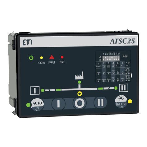
ETI ATSC25 User manual

ETI

ETI ATSC25 User manual

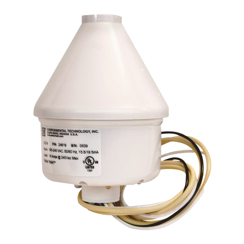
ETI SNOW SWITCH LCD-8 User manual

ETI

ETI SNOW SWITCH LCD-8 User manual

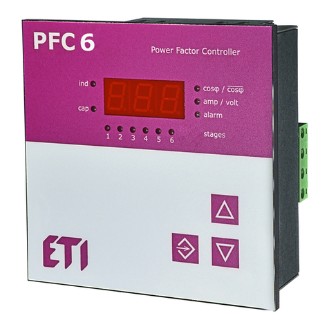
ETI PFC 6 RS Troubleshooting guide

ETI

ETI PFC 6 RS Troubleshooting guide

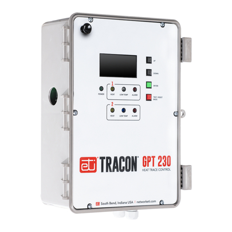
ETI Tracon GPT 230 User manual

ETI

ETI Tracon GPT 230 User manual

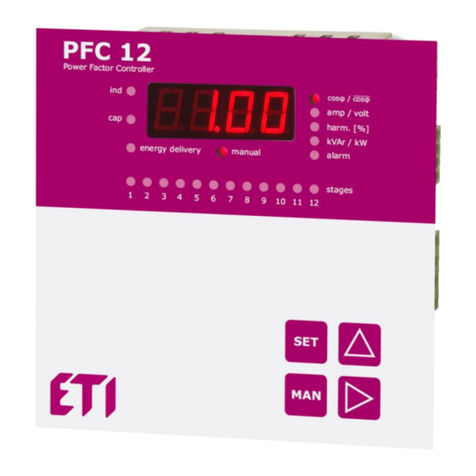
ETI PFC 12 RS Troubleshooting guide

ETI

ETI PFC 12 RS Troubleshooting guide

ETI SOLID GSX User manual

ETI

ETI SOLID GSX User manual

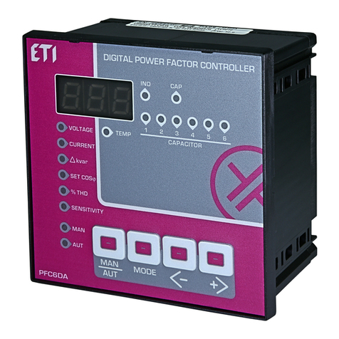
ETI PFC6DA User manual

ETI

ETI PFC6DA User manual

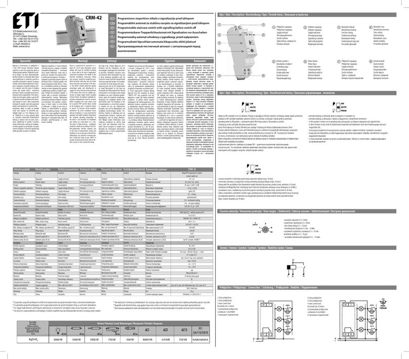
ETI CRM-42 User manual

ETI

ETI CRM-42 User manual

ETI Tracon FPT-130 User manual

ETI

ETI Tracon FPT-130 User manual

Popular Controllers manuals by other brands

Mitsubishi Electric NZ2MFB2-16A user manual

Mitsubishi Electric

Mitsubishi Electric NZ2MFB2-16A user manual

THORLABS BSC202 user guide

THORLABS

THORLABS BSC202 user guide

Global Fire Equipment GFE-PA-VOX-A quick start guide

Global Fire Equipment

Global Fire Equipment GFE-PA-VOX-A quick start guide

Omron SYSMAC CS Series Operation manual

Omron

Omron SYSMAC CS Series Operation manual

Festo DMES Series operating instructions

Festo

Festo DMES Series operating instructions

Zamel RTD-02 Manual instruction

Zamel

Zamel RTD-02 Manual instruction

Demco ACTUATOR DA20 Operator's manual

Demco

Demco ACTUATOR DA20 Operator's manual

Nachi EZ-CFDL Series instruction manual

Nachi

Nachi EZ-CFDL Series instruction manual

Promation Engineering P7-24PN4-DC Installation & operation manual

Promation Engineering

Promation Engineering P7-24PN4-DC Installation & operation manual

Yamato V instruction manual

Yamato

Yamato V instruction manual

iNels DA3-22M instruction manual

iNels

iNels DA3-22M instruction manual

Syntec S08-SMD-33B Series installation instructions

Syntec

Syntec S08-SMD-33B Series installation instructions

Danfoss CCR3+ operating guide

Danfoss

Danfoss CCR3+ operating guide

ECD OvenRIDER NL2+ Quick reference guide

ECD

ECD OvenRIDER NL2+ Quick reference guide

Linak BusLink LA14 user manual

Linak

Linak BusLink LA14 user manual

Bosch D2212B Operation and installation guide

Bosch

Bosch D2212B Operation and installation guide

Siemens Flowrite 599 Series installation instructions

Siemens

Siemens Flowrite 599 Series installation instructions

Victor VLINK V440 Startup guide

Victor

Victor VLINK V440 Startup guide

manuals.online logo
manuals.online logoBrands
  • About & Mission
  • Contact us
  • Privacy Policy
  • Terms and Conditions

Copyright 2025 Manuals.Online. All Rights Reserved.