Fireye NEXUS NX6100 series User manual

1of 27
Type2 Oxygen probe system for Nexus
NX6100 and PPC6000
Supplement to NEX6101 & PPC6001
NXPK2244
July 24, 2019

2of 27
1. Introduction
This supplement is intended to be additional information to that contained in the standard Nexus
Installation and Commissioning Bulletin. This document details the wiring configurations for the
Type2 Oxygen probe system. The Type2 component system will replace the original system by
March 31st, 2017.
The Type2 probe system employs a probe controller and trim interface, model NXO2TRIM, with
probe models NX6083-1, NX6083-2 and NX6083-3.
CAUTION
Unlike the NXO2INT, which is Line voltage supplied, the
NXO2TRIM only requires CANbus power 24V.
Connection of Line voltages to the NXO2TRIM will damage the
product beyond repair.
The interconnection system between the NXO2TRIM and the
NXPK224455-56-57probes is considerably different to the wiring
system between the NXO2INT and the NXO2PK-x probe
Installation and Wiring.
1.1 Installation.
1.1.1 Oxygen probe.
The NXPK224455-56-57 oxygen probe is available in the same sample tube lengths as the NXO2PK
probes and is designed for use with the existing mounting flange system.
1.1.2 Oxygen probe interface.
The NXO2TRIM oxygen trim interface enclosure has different dimensions and mounting points,
compared to the original design. The following drawing gives the dimensional information and the
details required to fix the interface to a wall or panel surface.

3of 27

4of 27

5of 27
1.2 Wiring
CAUTION
WIRING INSTALLATION MUST BE CARRIED OUT BY A COMPETENT ELECTRICIAN AND IS
SUBJECT TO I.E.E. WIRING REGULATIONS (BS 7671:1992) AND/OR LOCAL STANDARDS,
WHICH MAY PREVAIL.
HAZARDOUS VOLTAGES MUST BE ISOLATED BEFORE SERVICE WORK IS CARRIED OUT.
The main controller MUST be mounted within a ‘burner cabinet’ or similar panel and MUST be
earthed to the overall enclosure to ensure safe and reliable operation using the largest cross-
sectional area green/yellow earth wire available. Do not use a green/yellow conductor for any
purpose other than earth. The metal body of all other component parts MUST be connected to
earth using a green/yellow conductor.
To comply with EMC requirements, the controller and any optional units must be wired using the
specified cable sizes, and screen connections, observing any maximum cable length limitations.
Cabinet designers MUST ensure that Line voltage and Extra Low Voltage (ELV) cables are
segregated within the burner cabinet, distribution panels and conduits.
The manufacturer of this equipment recommends the use of bootlace ferules on all wire ends,
as a “best practice”.
Bootlace
Ferrules
All cabling that is required to operate at above 50V must be multi-strand single core, PVC insulated,
at least 0.5 mm2(20 AWG) and should meet the requirements of I.E.C. 227 or I.E.C. 225.
Read this document in conjunction with the product bulletin
NEX-6101 & PPC6000
Disconnect the power supply before beginning installation to
prevent electrical shock, equipment and/or control damage. More
than one power supply disconnect may be involved.
Wiring must comply with all applicable codes, ordinances and
regulations.
Ensure the maximum total load on the CANbus cabling (servo-
motors, display etc) is within the specifications for the cable being
used.
This equipment MUST NOT be directly connected to any part of a
SELV circuit.

6of 27
Secure all cables carried in conduit at both ends using a suitable anchorage method in the cabinet.
Connect all signal cable ‘braid’ screens to earth using the screen termination clamps provided on the
controller. Connect all cable screens to earth at the controller only, unless stated otherwise in this
section.
The equipment described in this manual has been tested for compliance to the CE directives listed in
the section headed ‘Approvals’. However, once connected to a burner and other associated control
devices, it is the responsibility of the installer to ensure the complete installation meets the
requirements of the CE or other local codes/directives relevant to the particular installation.
1.3 NXO2TRIM terminal designation and wiring requirements
1.3.1 Wire specification and interconnection.
The electrical connection between the Nexus series controller must be to the CANbus 4-core screen
cable specification in the main product manual, NEX-6101 or PPC-6001. Connect the CAN cable
‘braid’ screen at the controller, using the screen termination clamps provided at the controller.
Terminate the ‘braid’ screen for all other connections in the NXO2TRIM enclosure at ring terminal
point.
Incorrect connection or application of excess voltage will damage or destroy the devices
being connected.
The electrical cable specification for connections between the NXO2TRIM and NX6083-X probe
must be as follows:
Cable function Specification
Cell heater and O2
measurement.
Max Voltage in use 14V d.c.
6-core cable with each core 16/0.2mm (20 AWG) and with
overall braded screen. Cable covered in PVC sheath.
Resistance per core 40 milliohms/metre.
Maximum working voltage 440V rms.
Maximum length between the probe and controller is 10m
(33ft).
Flue gas temperature
measurement.
Max Voltage in use 5V d.c.
Type ‘K’ compensating cable.
2-core PVC insulated cable with 7/0.2mm (24awg) conductors,
covered in overall PVC sheath.

7of 27
1.3.2 Terminal connections and layout.
Terminal No. Module Function Voltage Rating
PG1 O2 Trim Interface CAN 24Vac Supply 24 – 32Vac
PG2 O2 Trim Interface CAN 24Vac Supply 24 – 32Vac
PG3 O2 Trim Interface CAN + (High) 0-5V
PG4 O2 Trim Interface CAN – (Low) 0-5V
PG5 O2 Trim Interface GND (4-20mA Input 0V) 0V
PG6 O2 Trim Interface 4-20mA Input 1 0-5V
PG7 O2 Trim Interface 4-20mA Input 2 0-5V
PG8 O2 Trim Interface 4-20mA Input 3 0-5V
PG9 O2 Trim Interface GND (4-20mA Input 0V) 0V
PH1 O2 Trim Interface Probe 1 (Black) 0-14V
PH2 O2 Trim Interface Probe 2 (Red) 0-14V
PH3 O2 Trim Interface Probe 3 (Yellow) 0-14V
PH4 O2 Trim Interface Probe 4 (Green) 0-14V
PH5 O2 Trim Interface Probe 5 (Blue) 0-14V
PH6 O2 Trim Interface Probe 6 (White) 0-14V
PH7 O2 Trim Interface Flue gas thermocouple White 0-5V
PH8 O2 Trim Interface Flue gas thermocouple Green 0-5V
The connection scheme between the NXO2TRIM and NX6083-X is by direct connection,
terminal1 to 1, 2 to 2 and so on up to terminal 8. See the reference to PH above.
(CO Signal +)
(O2 Signal +)
(N/A)

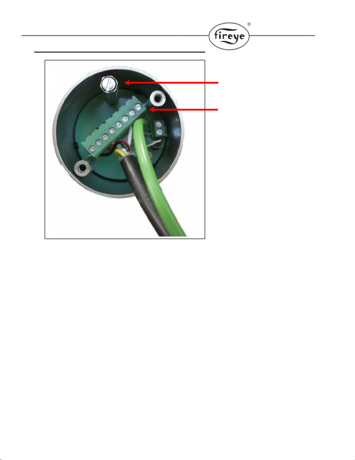
8of 27
Cable entries on this face
Probe connection terminals.
PH1 to PH8
CAN and 4-20mA connection
terminals PG1 to PG8
Ring terminal point for screen
termination.
Internal view of NXO2TRIM.
Do not Connect 120Vac NXO2TRIM is 24Vac supplied
9of 27
Calibration port.
Removable terminal block
NOTE: There is no screen
termination point. The screen in
the 6-way cable must be cut
short to the PVC outer cover.
View of NXPK224455-56-57 oxygen probe terminals.

10 of 27
2. Commissioning and Calibration process.
There are no changes to the Commissioning and Calibration process when using the Type2 Oxygen
probe system. A card with Calibration data will be provided with every new probe in a similar way to
that for NXO2PK probe.
Refer to bulletin NEX-6101 or PPC6001 for all processes.
Commissioning Oxygen Trim
In order for the oxygen trim system to function correctly, the following information must be entered:
1. Enter the appropriate option parameters from 30.0 to 42.6 as required.
With the burner off, enter commission mode (See section 5 of the PPC-6001 and NEX-6101
bulletins). To get the trim operational it is only necessary to address all option parameters
with the
Refer to options 30.0 thru 42.6 inclusive for details of parameters that may be entered.
2. Flow values and O2 set points. The flow and O2 values may be entered manually by the
engineer (option 34.5), or the system can automatically calculate the values and enter them
itself by using automatic trim commissioning (option 30.9).
If the automatic trim commissioning is performed, the engineer MUST CHECK THAT THE
VALUES ENTERED ARE VALID AND SAFE AFTER COMPLETION. Additionally, the
oxygen probe calibration should be checked before and after the procedure since the results
depend highly upon measurements taken using the probe.
Before proceeding to enter the oxygen set points for each profile, a few points relating to the oxygen trim
option should be considered.
No trim is applied which would require a drive to move above its high fire position or below its low
fire position.
The flow for each profile position must be entered to ensure correct operation. The flow can either
be measured for each profile position or calculated as a percentage with respect to the flow at
high fire.
O 2
WARNING
Use extreme care when entering flow values and oxygen set points.
Incorrect setting of either could cause a hazardous situation to occur,
and serious injury or death could result.
If the flow values and oxygen set points have been up-loaded it is
essential that the combustion is verified at each firing position.
If using automatic oxygen trim commissioning it is the sole
responsibility of the commissioning engineer to ensure the values
calculated by the system are correct and will not cause a hazardous
condition to occur.
Once the oxygen trim is commissioned the trim flow limit must be set
to ensure a fault in the oxygen trim will not cause a hazardous
condition to occur.
symbol

11 of 27
Using adjust ratio mode to modify and existing oxygen profile manually, follow steps 1 -12
listed below.
To adjust an oxygen set point or enter an air flow value in the firing range, use the following procedure.
The manual calculation of the values to be entered here is covered in the next section.
1. Enter adjust ratio mode (See section 5.6).
2. Ensure oxygen trim is set to monitor only 30.5 = 0.
3. Use the scroll keys to select the desired set point and move up and/or down (A4 for
example). The system will modulate to the selected set point and the number displayed will
flash to indicate that the drives are modulating.
4. Wait for the number in the display to be illuminated steadily. This means that the drives have
arrived at the selected set point.
5. The display will allow scrolling sideways to show flow and ‘O2’ in addition to the servo-motor
positions to indicate that the system is expecting a flow value and an oxygen set point to be
entered for the current profile set point. To check the current oxygen measured value use
the engineer’s key EK44.
6. Once the oxygen value is shown on the display use the scroll keys to position the ‘>’ pointing
to the ‘O2’ value use the UP/DOWN keys to adjust the oxygen setpoint as necessary. The
display will start flashing to indicate that a change has been made.
7. If the new oxygen set point value is wanted, press the ENTER key. The value will be stored in
memory.
8. If the new oxygen set point value is not wanted or an adjustment is not required, press the
NEXT key to return to the value stored in memory.
9. Once the flow value is shown on the display use the scroll keys to position the’>’ pointing to
the ‘FLO’ value use the UP/DOWN keys to adjust the flow value as necessary. The display
will show the air flow value, represented as a percentage of the air flow when the drives are
at the HIGH FIRE position. The display will start flashing to indicate that a change has been
made.
10. If the new flow value is not wanted or an adjustment is not required, press the NEXT key to
return to the value stored in memory.
11. If it is necessary to adjust another set point in the firing range, repeat the above procedure
from step 3.
CAUTION
When using the adjust ratio mode, it is not possible for the unit to check drive
positions at all times. It is the responsibility of the engineer to check that motors
and valves are responding correctly.
12 of 27
12. After modifying an existing O2 trim profile, use Option 30.8 to reset the feed forward function.
See option 30.8 for details.
Option 30.0 – Oxygen probe interface serial number LV3
Each CANbus device connected to the system has a unique serial number allocated to it during
production testing. This number cannot be changed and is used to uniquely identify each device.
When the system is in commissioning mode the serial number of all the connected devices is read by the
NX6100 and displayed as a ‘list’ to allow the selection of the relevant serial number unit to be made.
Scrolling the list in an upward direction will scroll through all oxygen probe interface options available until
‘0, nothing’ is displayed. Enter this value to disconnect the specified device from any hardware.
Scrolling the list in a downward direction will stop when the currently selected item is displayed, and the
value will stop flashing.
The display will show type information for each device present (such as ‘O2 probe’), but the
commissioning engineer should be aware of which serial number device is being used for which function.
Option 30.1 - Oxygen probe calibration offset value (0 – 999) LV3
This option parameter is only available if option 30.0 is non-zero.
This option parameter must be set to the calibration offset value that is specified with the Fireye probe
supplied.
When using another manufacturer’s O2probe with a 4-20mA signal for O2value, enter the O2 value for
4.0mA in this option parameter. Example 0% O2 = 000.
Option 30.2 - Oxygen probe calibration gain value (0 – 999) LV3
This option parameter is only available if option 30.0 is non-zero.
This option parameter must be set to the calibration gain value that is specified with the Fireye probe
supplied.
When using another manufacturer’s O2probe with a 4-20mA signal for the O2value, enter the O2 value
for 20.0mA in this option parameter. Example 21% O2 = 210.
NOTE: If the value of 30.1 and 30.2 are both below 300, the NX6100 will utilize the analog input on
the NXO2TRIM terminals PG6(+)PG5(-)to determine the O2 signal.
Option 30.3 - Oxygen probe calibration gas concentration (0.00 – 9.99%) LV3
This option parameter is only available if option 30.0 is non-zero.
This option parameter must be set to the percentage oxygen concentration of the calibration gas used if
the probe is to be calibrated using a reference gas (see option parameter 30.6). The range of this
parameter is 0.00 - 9.99%.
O 2
O 2
O 2

13 of 27
Option 30.4 – Flue and inlet sensor temperature units (0 – 1) LV3
This option parameter is only available if option 30.0 is non zero.
This option parameter must be set to select the units for display of both temperatures on either C or F.
Option parameter
30.4 value Meaning
0C. The temperature value will be displayed in C.
1F. The temperature value will be displayed in F.
Please note that temperature limits MUST be set in the correct units.
If a 4-20mA input is used for O2signal, a NXIATS is required to calculate efficiency in conjunction with a
K type thermocouple measuring flue temperature, connected to the appropriate inputs in the NX02TRIM .
Option 30.5 - Oxygen input function (0/1) LV3
This option parameter can only be set above 1 if option 30.0 is non zero.
Using this option parameter, it is possible to configure the oxygen input for a monitoring function or trim
function. The two functions are explained below:
Option parameter 30.5
value
Meaning
0
Monitor only. The oxygen value is only used to provide a display of the
measured oxygen level.
1
Closed loop trim. The oxygen value is used to provide both a display of
the measured oxygen level and a feedback signal for closed loop trim
control function of the NX6100 series control.
Option 30.6 - Oxygen probe calibrate enable (0 – 2) LV3
This option parameter is only available if option 30.0 is non-zero.
This option parameter must be used when calibrating the oxygen probe.
There are three possible values:
Option parameter 30.6
value
Meaning
0
No calibrate. This is the normal operating condition, where the probe is
used to measure the oxygen concentration in the flue.
1
Calibrate in air. The probe will be calibrated for 'offset' at the normal
atmospheric oxygen concentration.
2
Calibrate in reference gas. The probe will be calibrated for 'gain' in a
reference gas with a nominal oxygen concentration the level specified in
option parameter 30.3 (typically 3.0%).
Once this calibration has been successfully completed the values in 30.1 and 30.2 will be automatically
updated.
O 2
O 2

14 of 27
Option 30.7 - Boiler transport delay (5 – 60 seconds) LV3
Boiler transport delay is the time taken for 'gas' to travel from the burner to the oxygen probe. This delay
varies with burner fire rate.
In order for the oxygen trim control loop to be stable, this parameter must be set accurately to the
transport delay of the boiler when at low fire. This option may be set between 5and 60 seconds
inclusive.
To measure the transport delay, ignite the burner and enter adjust ratio mode. Select the low fire set
point and allow time for the flue oxygen reading to settle. Once the oxygen reading is steady, make a
step change to the fuel/air ratio and start a timer. As soon as the measured oxygen reading begins
to change, stop the timer. Set the option parameter to the recorded timer value in seconds.
Automatic trim commissioning (option 30.9) will attempt to set this automatically. However the value
must be checked by the engineer.
Option 30.8 - Reset oxygen trim profile (0/1) LV3
During full automatic operation, the O2 trim system will learn and store the percentage of trim applied to
various firing rates. This provides a “feed forward” aspect to O2 trim. If any changes to target O2 values
are made after the system has been in operation, the trim profile must be reset so as to not apply
previous trim feed forward. A new trim profile will be learned as the burner modulates. Only the trim
profile is affected. The Oxygen set points and flow values are not changed.
This option parameter allows the learned trim profile to be reset. If the option is set to 1 any learned
profile currently held in memory will be reset and the trim drives will return to their commissioned positions
for the corresponding modulation position. Once the profile has been reset this option parameter will
automatically be reset to 0.
Option 30.9 – Automatic trim commissioning (0 / 1) LV3
The unit is able to automate the manual calculation procedures (option parameter 34.5), automatically
calculating and entering flow values, oxygen trim set points, and boiler transport delay. The automatic
commissioning procedure will only work if the following conditions are met:
Option parameter 30.9 (automatic trim commissioning) is set to 1
An oxygen probe is fitted and fully operational
The unit is in adjust ratio with the burner firing a single fuel only
A hydrocarbon ratio has been entered for the current fuel (see option parameters 35.1 — 35.4).
The auto commissioning procedure will usually take between 10 and 30 minutes (depending on number
of set points), and is performed by the unit as follows:
1. Beginning with high fire, the unit moves the drives to each point in the firing range. The
display will show O2.
2. When the measured oxygen reading settles, the unit stores the measured oxygen reading as
the new oxygen set point.
3. The drives are moved to the next position directly below high fire (Ph-1) and wait for the
oxygen to stabilize.
O 2

15 of 27
4. The unit moves the air drives up to the point above the current set point, leaving the fuel drive
in the same position. The display will show ‘Flow calc An + 1’.
5. When the new oxygen reading settles, the unit calculates and stores the new flow value. If
the oxygen reading exceeds 15.0% during this stage, the unit shuts the burner down with
F77.
6. When the unit has completed the low fire point, the measured boiler transport delay (at low
fire) is stored in option parameter 30.7. Option parameter 30.5 (oxygen trim enable) is set to
zero.
7. You must use “adjust ratio” mode to confirm each position from P3 (low fire) to Ph (high fire).
If the flow values appear reasonable (about 4 to 6% change at each position) once you have
finished, setting option 30.5 to 1 will enable O2 trim. There is a one-minute delay after exiting
commissioning mode before trim will enable. If the flow values are unreasonable, they may
be adjusted manually by placing the cursor to the “FLO” position and using the up/down
arrows set the desired flow value. Using EK44 verify the O2 levels at each position and adjust
to match if required. EK46 will help troubleshoot O2 trim issues.
BEFORE ENABLING TRIM, USE ADJUSTS RATIO MODE TO MANUALLY CHECK THE
CALCULATED FLOW VALUES, OXYGEN SETPOINTS AND TRANSPORT DELAY. THE LOW FIRE
PERCENTAGE FLOW VALUE SHOULD CONFORM APPROXIMATELY TO THE TURN-DOWN RATIO
OF THE BURNER.
SUMMARY
To perform automatic trim commissioning, follow the procedure below:
1. If the probe is new, enter the offset and gain values in option parameters 30.1 and 30.2 which
are supplied with the probe. To re-calibrate the probe referto section 8.
2. Enter adjust ratio mode (See section 5).
3. Enable automatic trim commissioning by setting option parameter 30.9 to 1.
4. Wait for procedure to finish.
5. Check that the 02, flow and transport delay values are sensible. Use EK44 for O2 value.
6. Check calibration of the oxygen probe.
7. Confirm setup using “adjust ratio” mode.
NOTE: If the boiler shuts off for any reason during automatic commissioning, the sequence will continue
when the boiler re-starts.
Option parameter
30.9 value
Meaning
0
Not selected.
1
Perform automatic trim characterization. The control will attempt to
characterize the burner profile by calculating flow values and selecting oxygen
set points to match the currently commissioned points.
Automatic trim commissioning will be performed under the following
conditions:
An oxygen probe is fitted and fully operational
The control is in adjust ratio mode.
A hydrocarbon ratio has been entered for the current fuel (see option
parameters 35.1 – 35.4).

16 of 27
Option 31.0 - Limit Modulation Range (0 to 1) LV3
By default, the control modulates the burner between the set-points P3(low fire) and Ph(high fire), where
Phis the last set-point entered in commission ratio mode. If oxygen trim is fitted, it is not possible for any
drive position to be trimmed lower than point P3(low fire) or higher than point Ph(high fire). Basically, you
can’t take fuel or air off at low fire, and you can’t add fuel or air at high fire.
This option parameter allows the engineer to overcome this limitation in one of two ways. First the
modulation range of the burner can be limited so that the burner may only modulate between points P4
(one set-point above low fire) and Ph-1 (one set-point below high fire). Since oxygen trim is not affected by
this limitation, each drive may be trimmed between the points P3and Ph. This means that it is not possible
to over-fire or under-fire the burner but a degree of trim may still be achieved at high and low fire. Note
that this option may reduce the turn down of the boiler.
Another option, allows the control to adaptively adjust the modulation rate so that the required amount of
trim can be applied. The turn down of the boiler will not normally be limited because the high and low fire
positions of the trimmed drives will still be attained.
Option parameter
31.0 value
Meaning
0
Modulation not limited. Burner modulates from P3to Ph.
Oxygen trim works over full range from P3to Ph, but may not be able to apply
trim at high fire, or low fire – depending on trim direction.
The burner always modulates to the desired modulation rate, which may limit
the system’s ability to maintain the desired oxygen value.
1
Normal modulation range limited to P4to Ph-1 always.
Oxygen trim works over full range from P3to Ph, and can apply extra trim at
low and high fire – limited by P3and Ph.
This setting is useful when there is extra capacity (usually air flow) available
for the burner, but otherwise it will reduce the turn-down ratio of the boiler.
Options 31.1 to 31.4 - Trim Type for profiles 1 to 4 (0 to 2) LV3
These option parameters determine which drive will be trimmed (Air or Fuel) in profiles 1 to 4. These
parameters are used together with the parameters entered in option parameters 2.0 to 2.9 to determine
which drives are trimmed, and in which direction.
Parameter Meaning
31.1 Trim Type for profile 1
31.2 Trim Type for profile 2
31.3 Trim Type for profile 3
31.4 Trim Type for profile 4
Parameter value in
31.X
Meaning
0
No Trim. Do not apply oxygen trim when running on this profile.
1
Air Trim. Trim ‘Air’ drives when running on this profile (see option parameters
2.0 to 2.9.)
2
Fuel Trim. Trim ‘Fuel’ drives when running on this profile (see option
parameters 2.0 to 2.9.)
O 2

17 of 27
Option 32.0 - Trim limit default (0/1) LV3
0 = Default Trim Limit of 5%
1 = Enables options 32.1 to 32.4
Options 32.1 to 32.4 - Trim limits (0.0 – 25.0) LV3
Option 32.0 is only available if option 30.5 (oxygen input function) has been set for closed loop oxygen
trim.
It is possible for the system to trim the air or fuel drives up to a maximum deviation of ±25.0% of the total
air or fuel flow for the chosen trim drives.
If option 32.0 is set to 0, the default trim limit will be ± 5.0% for all profile selections. Option parameters
32.1 to 32.4 will not be available.
If option 32.0 is set to 1, it is possible to individually adjust the trim limit for each profile selection using
option parameters 32.1 to 32.4. The trim limit may be adjusted from 0.0% (no trim) up to a maximum of ±
25.0% (maximum allowable trim).
It is the responsibility of the commissioning engineer to ensure the trim limit set will not allow a
hazardous combustion condition to occur in the event of an oxygen probe failure. Where oxygen
is to be considered safety critical, option parameters 31.X should be used to setup a second
oxygen monitor. When a second oxygen monitoring system is used, the oxygen can be
considered fail-safe, and the trim limits can be set up to 50% instead of 25%.
Options 33.1 to 33.4 - Trim integral gain (Default 10%) LV3
Options 33.1 to 33.4 are only available if option 30.5 (oxygen input function) has been set for closed loop
oxygen trim.
In order for the oxygen trim control loop to be stable, the integral gain must be set correctly. Options 33.1
to 33.4 allow the integral gain to be set individually for each profile combination to any value between 0.0
and 99.9%. As a general recommendation, the integral gain should be initially set to 10.0%. This value
must be set above 0.0 for the system to apply trim.
If the burner is firing, it is only possible to make an adjustment to the option parameter that relates to the
selected profile. If the burner is not firing, the integral gain for any profile selection may be adjusted.
Option 34.0 - Trim proportional gain (0/1) LV3
Options 34.1 to 34.4 - Trim proportional gain (0.0 – 99.9%) LV3
Options 34.0 to 34.4 are only available if option 30.5 (oxygen input function) has been set for closed loop
oxygen trim.
If oxygen trim proportional gain is not required for any profile selection, set option parameter 34.0 to 0.
If oxygen trim proportional gain is required, set option parameter 34.0 to 1. Option parameters 34.1 to
34.4 will then become available. Options 34.1 to 34.4 allow the loop gain to be set individually for each
profile selection to any value between 0.0 and 99.9%.
Oxygen trim proportional gain is not normally required.
O 2
O 2
O 2

18 of 27
Option 34.5 - Calculating and entering the flow values manually LV3
If the flow values are to be calculated manually, the procedure below must be followed.
Enter Adjust Ratio Mode with oxygen trim disabled as outlined above.
1. Select the high fire position. This will cause the display to show A(n), where n is the number of the
high fire profile point.
2. Wait until the oxygen reading has stabilized, the value can be viewed using the engineer’s key.
3. Record the excess air value at location x in the table. For single fuel profiles, this value may be found
using the Engineer’s Key parameter EK48 (provided the hydrocarbon ratio has been entered into the
appropriate option parameter (35.1 - 35.4) for this fuel). For multiple fuel profiles, Refer to NOTE
under section Options 35.1 to 35.4.
4. Select the profile position immediately below high fire. This will cause the display to show A(n -1).
5. Wait until the oxygen reading has stabilized and record the excess air value at location a1in the table
6. Move air dampers 1 and 2 (if fitted) up until they stop, so that they are at the set point immediately
above the current position. Do not press enter.
7. Wait until the oxygen reading has stabilized, then record the excess air value at location b1in the
table, relating to the current profile position
8. Repeat the above for all other profile positions including low fire (profile position A3), recording each
time the values at locations a and b in the table. When extra air is added at P3, the time taken before
the flue oxygen reading starts to increase should be measured and entered into option parameter
30.7.
9. After completing the table for all Excess Air values a and b, complete the Excess Air + 100 column, by
adding 100 (i.e. y = x + 100, c = a + 100 and d = b + 100.
10.Complete the Ratio column by dividing c by d (i.e. e = c/d).
11.Complete the Airflow column by multiplying e by the previous value of f (i.e. fx= exfx-1).
12.If the system will be applying trim to the fuel, the fuel flow column must be completed. This is
achieved by multiplying the airflow at each point by the ratio of excess air + 100 at high fire divided by
the excess air + 100 at the actual point (i.e. gx= fx(y/cx)).
Example of table completed for A10 (high fire) to A8. In practice, the table must be filled out down to A3
(low fire).
Profile
position
Excess Air
Ex. Air + 100
y = x + 100
c = a + 100
d = b + 100
Ratio
Airflow
Fuel flow
High fire
= A10
x
10
y
110
----------------
99.9%
99.9%
1 = A9
a1
b1
8
33
c1
d1
108
133
e1= c1/d1
0.812
f1= e1(99.9)
81.1%
g1= f1(y/c1)
82.6%

19 of 27
Profile
position
Excess Air
Ex. Air + 100
y = x + 100
c = a + 100
d = b + 100
Ratio
Airflow
Fuel flow
2 = A8
a2
b2
9
20
c2
d2
109
120
e2= c2/d2
0.908
f2= e2(f1)
73.7%
g2= f2(y/c2)
74.4%
Table: Flow calculation table
Profile
position
Excess Air
Ex. Air + 100
y = x + 100
c = a + 100
d = b + 100
Ratio
Airflow
Fuel flow
High fire
= A
x
y
1 = A
a1
b1
c1
d1
e1= c1/d1
f1= e1(99.9)
g1= f1(y/c1)
2 = A
a2
b2
c2
d2
e2= c2/d2
f2= e2(f1)
g2= f2(y/c2)
3 = A
a3
b3
c3
d3
e3= c3/d3
f3= e3(f2)
g3= f3(y/c3)
4 = A
a4
b4
c4
d4
e4= c4/d4
f4= e4(f3)
g4= f4(y/c4)
5 = A
a5
b5
c5
d5
e5= c5/d5
f5= e5(f4)
g5= f5(y/c5)
6 = A
a6
b6
c6
d6
e6= c6/d6
f6= e6(f5)
g6= f6(y/c6)
7 = A
a7
b7
c7
d7
e7= c7/d7
f7= e7(f6)
g7= f7(y/c7)
8 = A
a8
b8
c8
d8
e8= c8/d8
f8= e8(f7)
g8= f8(y/c8)
9 = A
a9
b9
c9
d9
e9= c9/d9
f9= e9(f8)
g9= f9(y/c9)
10 = A
a10
b10
c10
d10
e10 = c10/d10
f10 = e10 (f9)
g10 = f10 (y/c10)
11 = A
a11
b11
c11
d11
e11 = c11/d11
f11 = e11 (f10)
g11 = f11 (y/c11)
12 = A
a12
b12
c12
d12
e12 = c12/d12
f12 = e12 (f11)
g12 = f12 (y/c12)
13 = A
a13
b13
c13
d13
e13 = c13/d13
f13 = e13 (f12)
g13 = f13 (y/c13)
14 = A
a14
b14
c14
d14
e14 = c14/d14
f14 = e14 (f13)
g14 = f14 (y/c14)

20 of 27
Profile
position
Excess Air
Ex. Air + 100
y = x + 100
c = a + 100
d = b + 100
Ratio
Airflow
Fuel flow
15 = A
a15
b15
c15
d15
e15 = c15/d15
f15 = e15 (f14)15
g15 = f15 (y/c15)
16 = A
a16
b16
c16
d16
e16 = c16/d16
f16 = e16 (f15)
g16 = f16 (y/c16)
17 = A
a17
b17
c17
d17
e17 = c17/d17
f17 = e17 (f16)
g17 = f17 (y/c17)
18 = A
a18
b18
c18
d18
e18 = c18/d18
f18 = e18 (f17)
g18 = f18 (y/c18)
19 = A
a19
b19
c19
d19
e19 = c19/d19
f19 = e19 (f18)
g19 = f19 (y/c19)
20 = A
a20
b20
c20
d20
E20 = c20/d20
f20 = e20 (f19)
g20 = f20 (y/c20)
Option 35.0 – Inlet temperature sensor serial number LV3
Each CANbus device connected to the system has a unique serial number allocated to it during
production testing. This number cannot be changed and is used to uniquely identify each device.
When the system is in commissioning mode the serial number of all the connected devices is read by the
NX6100 or PPC6000 and displayed as a ‘list’ to allow the selection of the relevant serial number unit to
be made.
Scrolling the list in an upward direction will scroll through all temperature sensor options available until ‘0,
nothing’ is displayed. Enter this value to disconnect the specified device from any hardware.
Scrolling the list in a downward direction will stop when the currently selected item is displayed, and the
value will stop flashing.
The display will show type information for each device present (such as ‘air temp’), but the commissioning
engineer should be aware of which serial number device is being used for which function.
Options 35.1 to 35.4-Hydrocarbon ratios of each fuel respectively (0.00 – 9.99)
LV3
If a display of calculated burner efficiency, or ‘automatic trim commissioning’ is required, the hydrocarbon
ratios for the required fuels must be entered. These may be set between 0.0 and 9.99 inclusive, where
the value entered is the hydrocarbon ratio x 10. For example, for a hydrocarbon ratio of 0.157, a value of
1.57 should be entered.
Note: When firing multiple fuels, the mixture between the fuels fired may vary across the firing range of
the burner. When this happens, the effective hydrocarbon ratio and calorific value of the fuel combination
O 2
O 2
Other manuals for NEXUS NX6100 series
3
This manual suits for next models
1
Table of contents
Other Fireye Industrial Equipment manuals


