Fireye BurnerPRO Operating instructions

BURNERPRO
TROUBLESHOOTING
August2020
Proprietary and Confidential
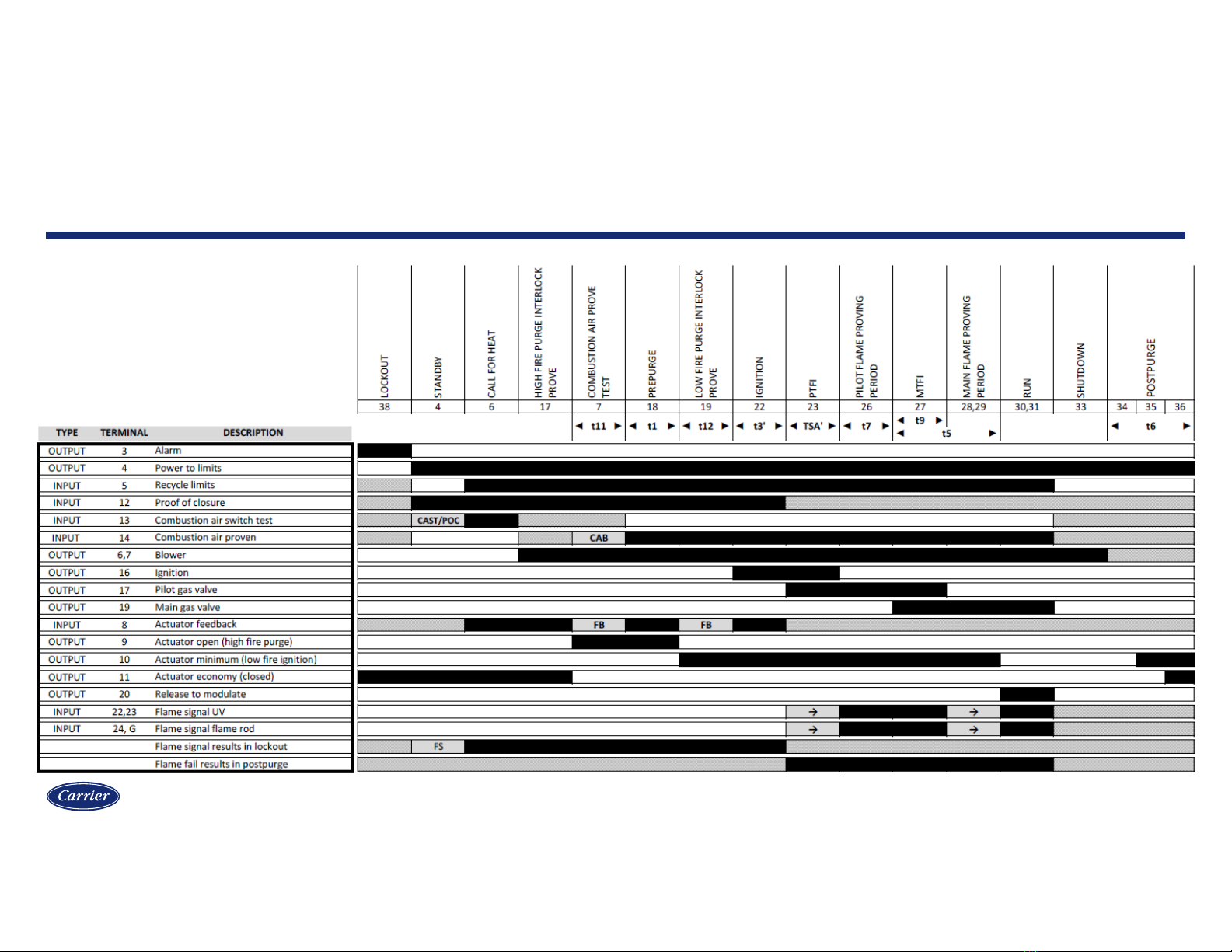
Sequence diagram
2
Without valve proving
Interrupted pilot

Proprietary and Confidential
Sequence diagram
3
With valve proving
Proprietary and Confidential
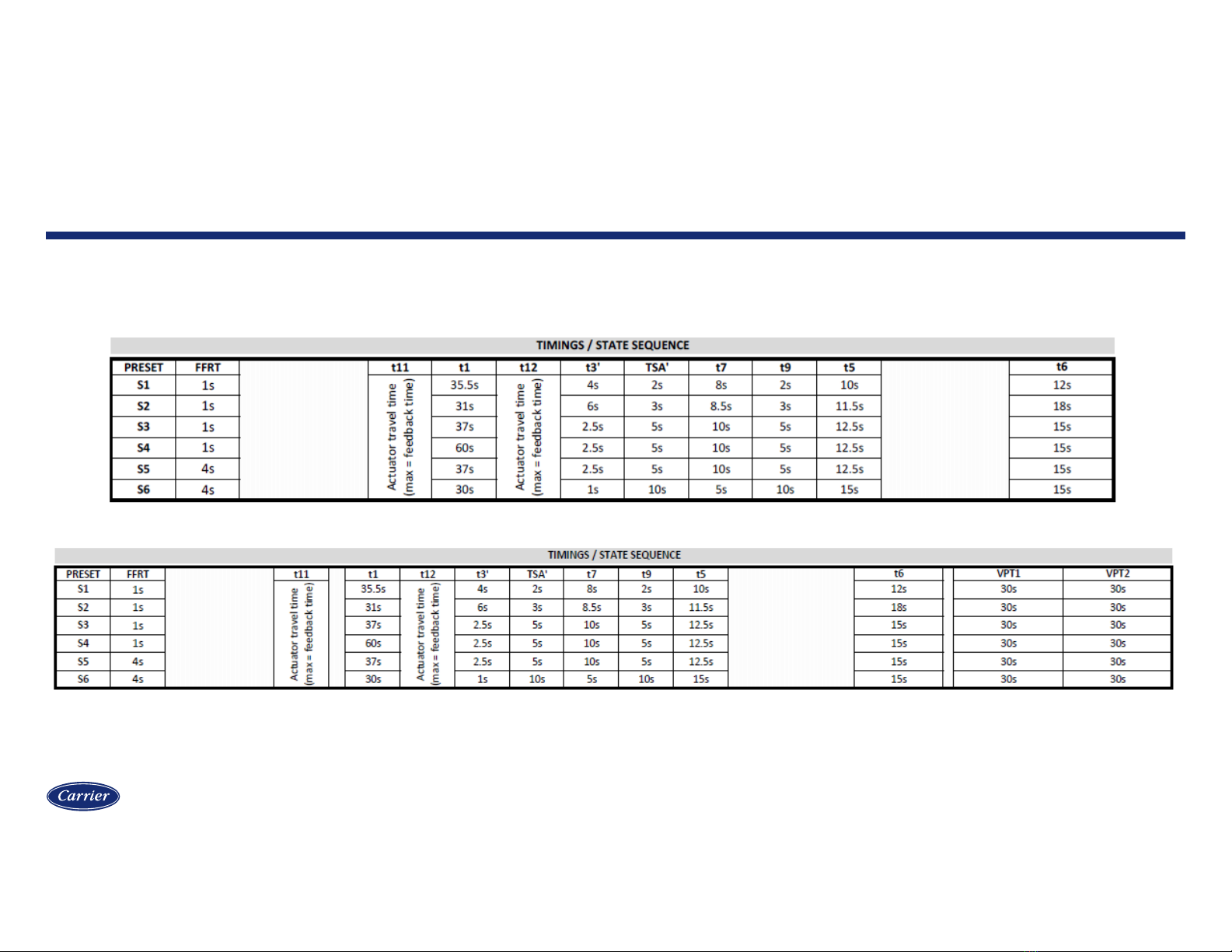
Standard timings S1-S6
Without valve proving:
With valve proving:
Sequence timings
4

Proprietary and Confidential
Terminal designations
5
Without valve proving

Proprietary and Confidential
Terminal designations
6
With valve proving

Proprietary and Confidential
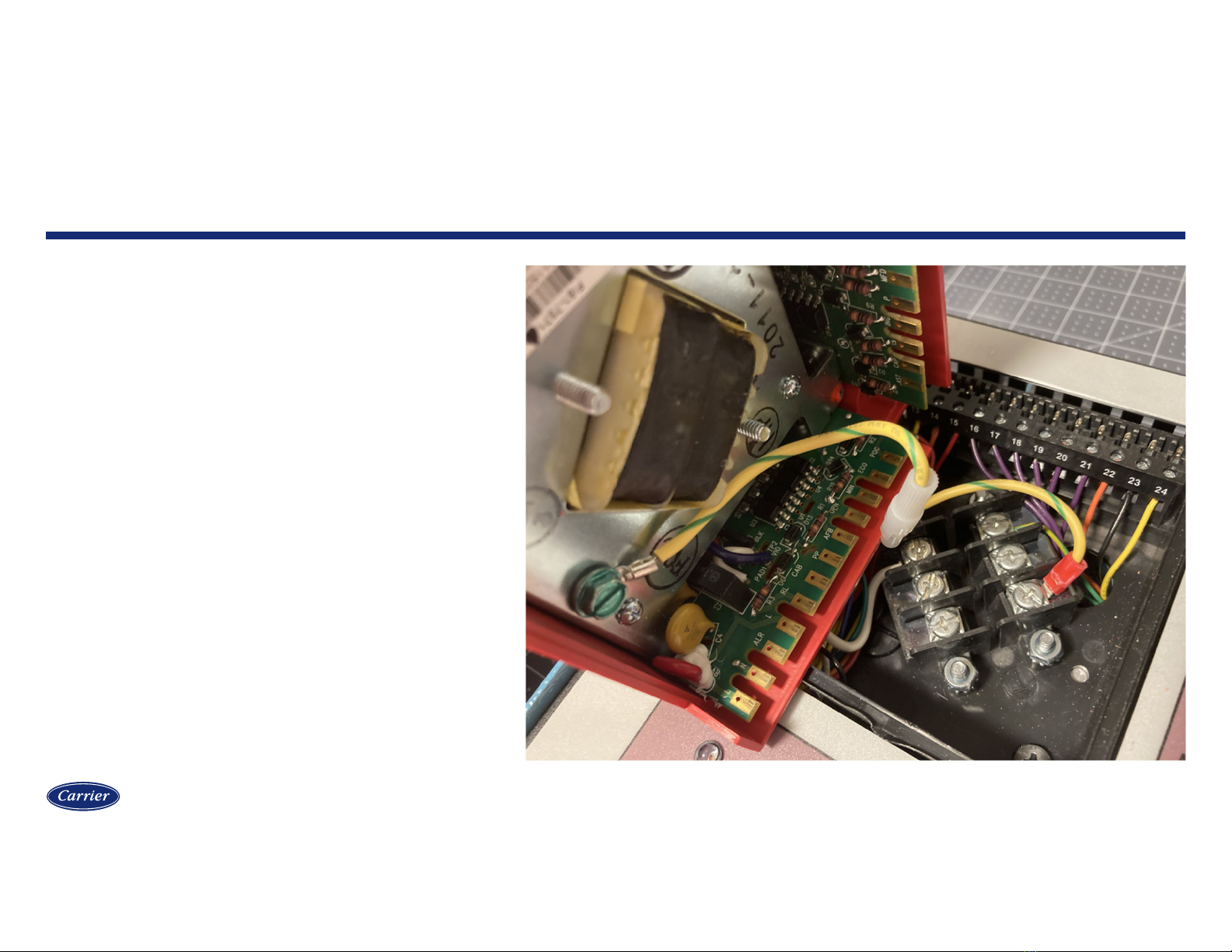
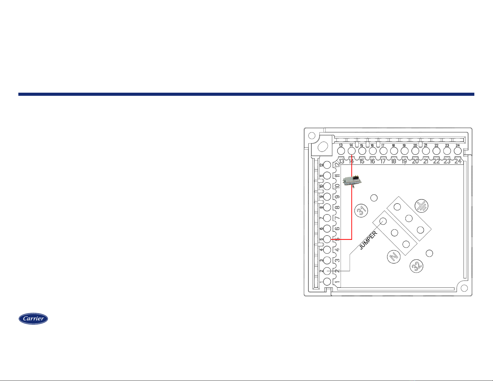
Wiring base
7
Common to Siemens LFL
The wiring base is common with the Siemens LFL
and the BurnerPRO is listed to function as a drop-in
replacement for the LFL.
Three common neutral and three common
grounding terminals are provided for use in
connecting external devices.
Proprietary and Confidential
Wiring base
8
Grounding leash
The BurnerPRO is grounded using a
quick-disconnect plug on a wired
grounding leash. This provides a more
positive ground over a copper spring,
which can lose contact over time.

Proprietary and Confidential
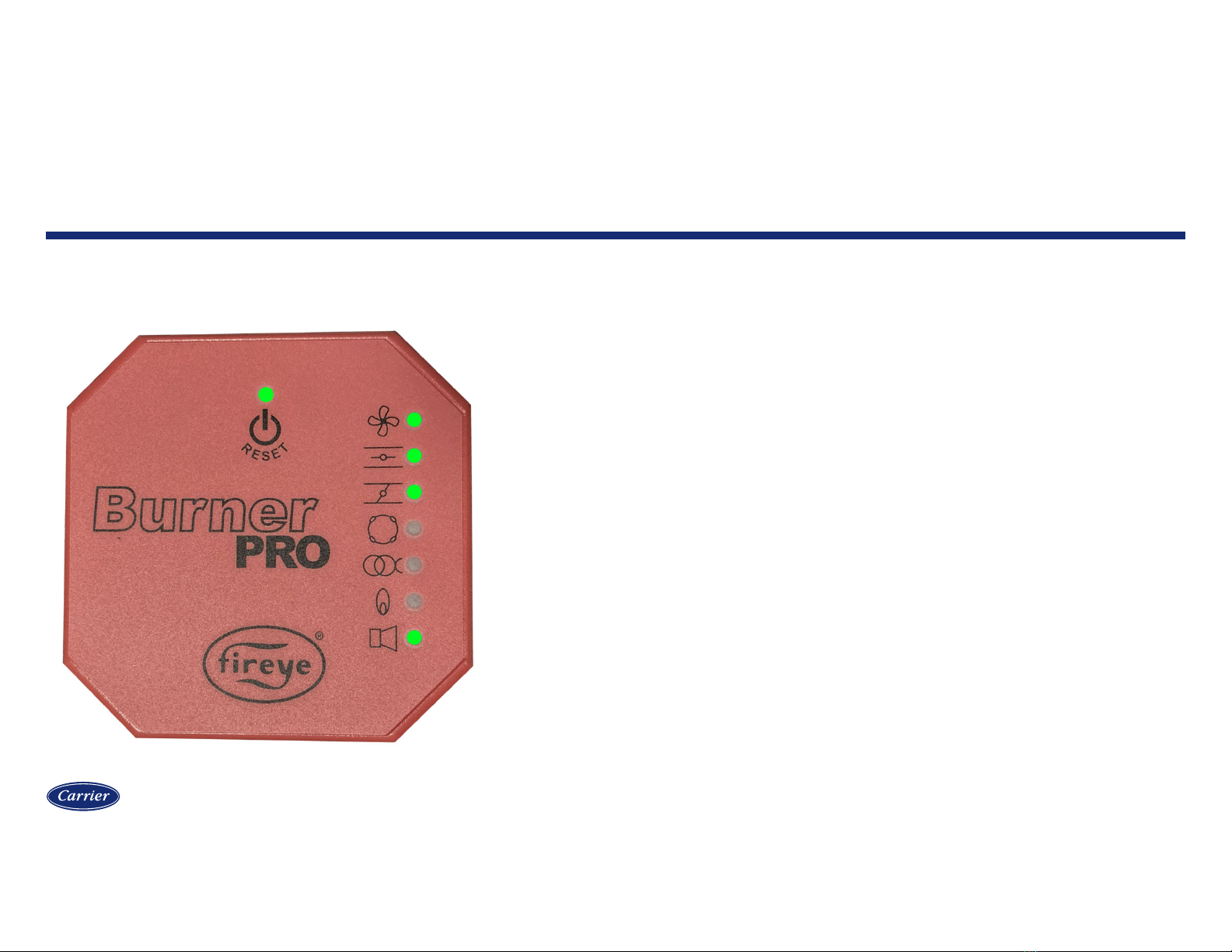
Smart LEDs
9
IGNITION
DAMPER OPEN
DAMPER CLOSED OR ECONOMY
AUTO MODE
STATUS
FLAME DETECTED
FAN
DEMAND
RESET BUTTON

Proprietary and Confidential
Sequence of operation
10
Standby
LED STATE The standby state is when there is not a call for heat.
Terminal 11 (ACTUATOR ECONOMY OUTPUT) is powered
with line voltage in this state.

Proprietary and Confidential
Sequence of operation
11
Lockout
LED STATE When in the lockout state, the combination of LEDs will
indicate the lockout code. These codes can be found in the
bulletin for the specific model. Shown is the lockout code for
STANDBY FALSE FLAME (flame detected while in standby
for more than 60 seconds).

Proprietary and Confidential
Sequence of operation
12
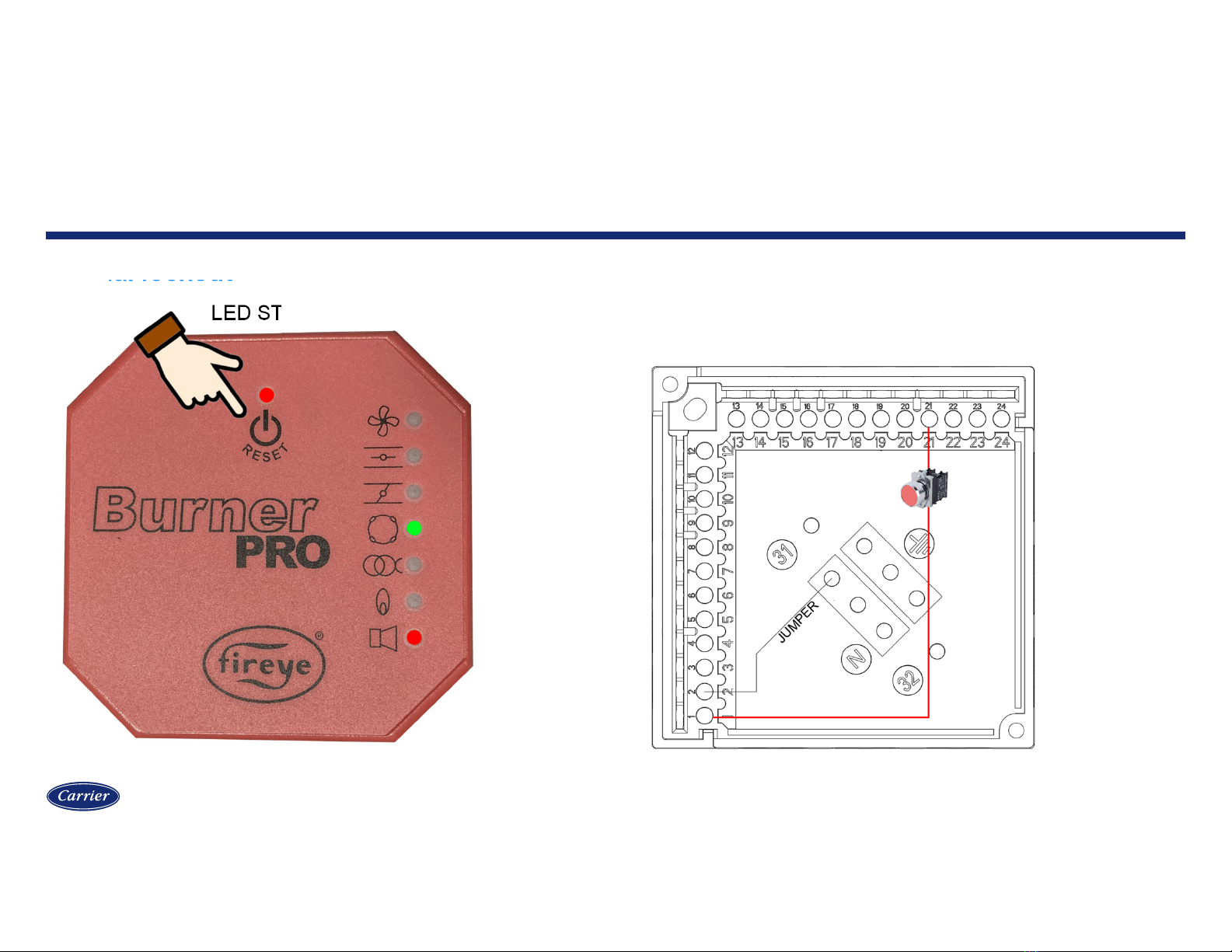
Lockout reset methods
LED STATE
A lockout condition can be reset by either pressing the reset button
on the control, or by applying line voltage to terminal 21 (REMOTE
RESET INPUT).
Proprietary and Confidential
Sequence of operation
13
Manual lockout
LED STATE
A lockout condition can be manually initiated by either pressing the reset
button on the control or by providing voltage to terminal 21. The lockout
code (shown here) indicated REMOTE RESET INPUT as the source of the
lockout. This can be used as a form of emergency shutdown.

Proprietary and Confidential
Sequence of operation
14
Call for heat input
Terminal 4 provides line voltage that is used to power the
operating limit string. After passing through all the limits in
series, line voltage is applied to terminal 5 to indicate that
the limits are complete and that there is a call for heat.

Proprietary and Confidential
Sequence of operation
15
Call for heat, checking air switch and POC
LED STATE When there is a call for heat, voltage must be detected on
both terminals 12 (PROOF OF CLOSURE INPUT) and
terminal 13 (AIR SWITCH NC INPUT) within 60 seconds.
Failure of either input to prove in time will result in a lockout.
For models with valve proving, both functions are wired in
series to terminal 13.
The air switch check is performed to verify that the air
switch is changing from closed to open (i.e., not jumpered
or stuck) between cycles.
Wire terminal 11 to terminals 12 and/or 13 to bypass
these checks. This works because terminal 11
(ACTUATOR ECONOMY OUTPUT) provides voltage
during this state.
BLINK
Proprietary and Confidential
Sequence of operation
16
Driving actuators to purge
LED STATE When the air switch check input and proof of closure input
prove, the sequence begins. Terminals 6 and 7 (FAN
OUTPUT) both energize. The LED above the reset button
lights green and the fan LED also lights green. The output
for terminal 11 (ACTUATOR ECONOMY OUTPUT) is no
longer powered. Instead, terminal 9 (ACTUATOR HIGH
FIRE OUTPUT) is powered instead as the BurnerPRO is
commanding the actuator to the purge position.
The LEDs for actuator open and actuator closed will
alternate as the control waits for feedback on terminal 8
(ACTUATOR FEEDBACK INPUT).
ALTERNATE
Proprietary and Confidential
Sequence of operation
17
Safety limits input
The safety limits must all be proven within the amount of
time specified for actuator travel time (timing t11). The count
begins when feedback is received to indicate that the
actuator is at the high fire position for purging.
The BurnerPRO will lockout if this input is not proven within
the specified duration.

Proprietary and Confidential
Sequence of operation
18
Purge
LED STATE When feedback is received to confirm that the actuator is at
the purge position, input must be received from the air
switch on terminal 14 (SAFETY LIMIT INPUT) within the
actuator travel time duration (timing t11). If the fan LED is
blinking, the control is waiting for this input. If the fan LED is
solid, this input has been received and the control is
counting the purge time (timing t1).

Proprietary and Confidential
Sequence of operation
19
CHECK MODE – purge
LED STATE Check mode can be applied to hold the burner in purge. To
do so, press and hold the reset button until the status LED
changes from green to amber. The fan LED will also blink
while in check mode.
Check mode in purge can be useful when a longer manual
purge is desired, or while checking other devices that
require the combustion air fan to run.
To exit check mode, simply press the reset button one time.
Check mode will automatically exit after 20 minutes.
Check mode will exit with a lockout (CHECK MODE
TIMEOUT).
BLINK

Proprietary and Confidential
Sequence of operation
20
Driving actuators to ignition
LED STATE After the purge timing is complete, the BurnerPRO will drive
the actuator to the ignition position. The output for terminal 9
(ACTUATOR HIGH FIRE OUTPUT) is no longer powered.
Instead, terminal 10 (ACTUATOR LOW FIRE OUTPUT) is
powered instead as the BurnerPRO is commanding the
actuator to the ignition position.
The LEDs for actuator open and actuator closed will
alternate as the control waits for feedback on terminal 8
(ACTUATOR FEEDBACK INPUT).
ALTERNATE
Other manuals for BurnerPRO
1
Table of contents


