ipf electronic OY32 Series User manual

Short-Manual •Subject to alteration! Stand: December 2022
ipf electronic gmbh
•Rosmarter Allee 14 •58762 Altena
│
Tel +49 2351 9365-0 •Fax +49 2351 9365-19
│
info@ipf-electronic.com •www.ipf-electronic.com 1
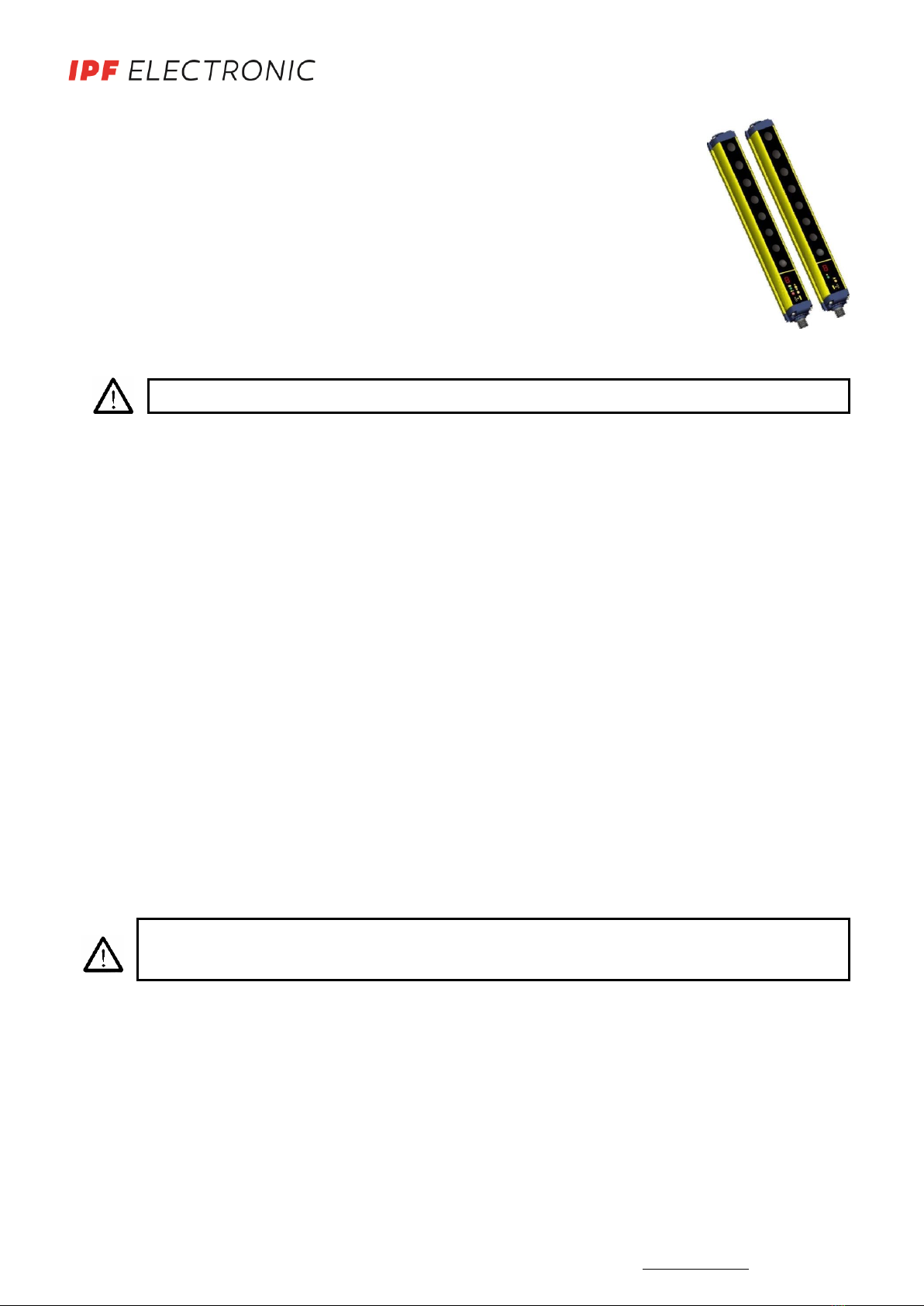
Quick Instruction Manual Safety Light Curtain OY32
Devices for finger- and handprotection
Safety Information
The following points must be observed for a correct and safe use of the OY32 safety device:
•The stopping system of the machine must be electrically controlled.
•This control system must be able to stop the dangerous movement of the machine within the
total machine stopping time T as per paragraph 1.3.3 of the manual included in the CD supplied
and during all working cycle phases.
•Mounting and connection of the safety light curtain must be carried out by qualified personnel
only, according to the indications included in the special sections (refer to sections 2; 3; 4; 5) and
in respect to the applicable standards.
•The safety light curtain must be securely placed in a particular position so that access to the
dangerous zone is not possible without the interruption of the beams.
•The personnel operating in the dangerous area must be well trained and must have adequate
knowledge of all the operating procedures of the safety light curtain.
•The TEST button must be located outside the protected area because the operator must check
the protected area during all Test operation.
•The RESET/RESTART button must be located outside the protected area because the operator
must check the protected area during all Reset/Restart operations.
•Please carefully read the instructions for the correct functioning before powering the light
curtain.
Precautions to be observed for the choice and installation
Make sure that the protection level assured by the OY32 device (Type 4) is compatible with the real
danger level of the machine to be controlled, according to EN 954-1 and EN 13849-1.
•The outputs (OSSD) of the ESPE must be used as machine stopping devices and not as command
devices. The machine must have its own START command.
•The dimension of the smallest object to be detected must be larger than the resolution level of
the device.
•The ESPE must be installed in a room complying with the technical characteristics indicated in
section 10 “Technical Data” of the manual include in the CD supplied.
•Do not install device near strong and/or flashing light sources or close to similar devices.

Short-Manual •Subject to alteration! Stand: December 2022
ipf electronic gmbh
•Rosmarter Allee 14 •58762 Altena
│
Tel +49 2351 9365-0 •Fax +49 2351 9365-19
│
info@ipf-electronic.com •www.ipf-electronic.com 2
•The presence of intense electromagnetic disturbances could jeopardise device functioning. This
condition shall be carefully assessed by seeking the advice of ipf electronic Technical service.
•The operating distance of the device can be reduced in presence of smog, fog or airborne dust.
•A sudden change in environment temperature, with very low minimum peaks, can generate a small
condensation layer on the lenses and so jeopardise functioning.
•Reflecting surfaces near the safety light curtain light beam (above, under or lateral) can cause passive
reflections that can jeopardize functioning.
•The safety device must be installed at a distance which is major or equal to the minimum safety
distance S to ensure that the operator can not reach the dangerous area until the moving dangerous
object has been blocked by the ESPE.
The failure to respect the safety distance reduces or cancels ESPE the protection function.
For more detailed information about calculation of safety distance, please refer to the complete
manual contained in the CD supplied or available for download on the homepage
www.ipf-electronic.com.
CONNECTIONS
RECEIVER (RX): EMITTER (TX):
1 = brown = +24V DC
2 = white = TEST
1 = white = RESET / RESTART (*) 3 = blue = 0V
2 = brown = +24V DC 4 = black = NOT USED
3 = green = EDM SELECTION
4 = yellow = EDM
5 = grey = OSSD 1
6 = pink = OSSD 2
7 = blue = 0V
8 = red = MANUAL / AUTOMATIC RESTART
(*) automatic RESTART →RESET-Function
manual RESTART →RESET/RESTART-Function

Short-Manual •Subject to alteration! Stand: December 2022
ipf electronic gmbh
•Rosmarter Allee 14 •58762 Altena
│
Tel +49 2351 9365-0 •Fax +49 2351 9365-19
│
info@ipf-electronic.com •www.ipf-electronic.com 3
Notes for the electrical connection
Function
Connection to
Status
TEST (Transmitter)
+ 24V DC
TEST ON
Not connected or 0V
TEST OFF
RESET (Receiver)
+ 24V DC
RESET ON
Not connected or 0V
RESET OFF
EDM (Receiver)
Normally closed
contact for a forceguided
relay
EDM is active
Not connected or 0V
EDM is not active
EDM SELECTION
(Receiver)
+ 24V DC
EDM OFF
Not connected or 0V
EDM ON
MAN/AUTO RESET
(Receiver)
OSSD1
AUTOMATIC RESET
OSSD2
MANUAL RESET

Short-Manual •Subject to alteration! Stand: December 2022
ipf electronic gmbh
•Rosmarter Allee 14 •58762 Altena
│
Tel +49 2351 9365-0 •Fax +49 2351 9365-19
│
info@ipf-electronic.com •www.ipf-electronic.com 4
ALIGNMENT PROCEDURE
The alignment between the emitting and the receiving units is necessary to obtain the correct functioning of
the light curtain.
A good alignment prevents output instability caused by dust or vibrations. The alignment is perfect if the
optical axes of the first and the last emitting unit beams coincide with the optical axes of the corresponding
elements of the receiving unit.
The beam used to synchronise the two units is the first after the connector. SYNC is the optics connected
with this beam and LAST is the optics connected to the last beam after the SYNC unit.
Receiver
Emitter
Signals are clearly identified through symbols allowing immediate reading, independent of bars directions.
A short description of the signalling LEDs is necessary to avoid misunderstandings.
Two yellow LEDs ( LAST, SYNC) on the receiver facilitate the alignment procedure.
Correct alignment procedure
The light curtain alignment can be effected only after having completed the mechanical installation and the
electrical connections. The following procedure has to be followed:
NOTE: The OY32 safety light curtain is equipped with a system which informs the user on the alignment
obtained.
The alignment function can be activated when powering the device, by keeping the normally open
RESET/RESTART contact closed for at least 0.5 seconds.
Last Optics (LAST)
First Optics =
Synchronisation Optics (SYNC)
LAST
SYNC
NORMAL
OP.
ON
NORMAL
OP.
SAFE(BREAK)

Short-Manual •Subject to alteration! Stand: December 2022
ipf electronic gmbh
•Rosmarter Allee 14 •58762 Altena
│
Tel +49 2351 9365-0 •Fax +49 2351 9365-19
│
info@ipf-electronic.com •www.ipf-electronic.com 5
Display
LED
NORMAL
OP.
LED
SAFE
(BREAK)
LED
Gelb
SYNC
LED
Gelb
LAST
Condition
Alignment
Status
OFF
ON
ON
ON
Sync: NOK
Last: NOK
Not aligned
OFF
Sync: NOK
Last: NOK
OFF
OFF
Sync: OK
Last: OK
Middle optics: NOK
ON
OFF
OFF
OFF
Each beam is over the min.
operating threshold and the
number of beam over the
threshold is included between 0
and 25%.
MINIMUM
alignment
ON
OFF
OFF
OFF
Each beam is over the min.
operating threshold and the
number of beam over the
threshold is included between
25 and 50%.
ON
OFF
OFF
OFF
Each beam is over the min.
operating threshold and the
number of beam over the
threshold is included between
50 and 75%.
ON
OFF
OFF
OFF
Each beam is over the min.
operating threshold and the
number of beam over the
threshold is included between
75 and 100%.
MAXIMUM
alignment
AKeep the receiver in a steady position and set the emitter until the yellow LED ( SYNC) is OFF. This
condition shows the alignment of the first synchronisation beam.
BRotate the emitter, pivoting on the lower optics axis, until the yellow LED ( LAST) is off.
NOTE: Ensure, that the green LED ( NORMAL OP) is steady on.
CDelimit the area in which the green LED ( ) is steady through some micro adjustments - for the first
and then fort he second unit - so to have the maximum alignment (4) and then place both units in the
centre of this area.
D Fix the two units firmly using brackets.
•Verify, that the green LED ( ) on the RX unit is ON and beams are not interrupted, then verify,
that the red LED SAFE (BREAK) ( ) on the TX unit turns ON if even one single beam is interrupted
(condition where an object has been detected).
•This verification shall be made with the special cylindrical test piece having a size suitable to the
resolution of the device used (refer section 2.2.6 “Controls after first installation”).

Short-Manual •Subject to alteration! Stand: December 2022
ipf electronic gmbh
•Rosmarter Allee 14 •58762 Altena
│
Tel +49 2351 9365-0 •Fax +49 2351 9365-19
│
info@ipf-electronic.com •www.ipf-electronic.com 6
E Switch OFF and ON the device in normal operating mode.
The alignment level is monitored also during device standard operating mode via display (see section 7.2
of the manual include in the CD supplied).
Once the curtain has been aligned and correctly fastened, the display signal is useful both to check the
alignment and show a change in the environmental conditions (occurrence of dust, light disturbance and
so on) via signal level monitoring.
DIAGNOSTICS FUNCTION
The operator can visualise the operating condition of the light curtains thanks to a one-digit display
positioned on both the RX and TX unit. OY32 also has four LEDs on the RX unit and two LEDs on the TX unit.
The figure below shows all signalling LEDs modes: OFF, ON and BLINKING.
The operator can evaluate the main causes of the system stopping or failure using the 7-segment display and
LEDs used to visualise the functions.

Short-Manual •Subject to alteration! Stand: December 2022
ipf electronic gmbh
•Rosmarter Allee 14 •58762 Altena
│
Tel +49 2351 9365-0 •Fax +49 2351 9365-19
│
info@ipf-electronic.com •www.ipf-electronic.com 7
For Receiver:
Function
Status
Meaning
LED
DIGIT
Normal
Operation
Alignment
See section 5
Test (red ON)
Light curtain being tested. OSSD
status shall be OFF
Emission
(OSSD ON)
(green ON)
Light curtain working in normal
operating conditions
Interruption
(OSSD OFF)
(red ON)
Light curtain working in safety
block conditions
Interlock,
Beams free
(red ON, yellow ON)
Light curtain in interlock, waiting
for restart. OSSD status must be
OFF
Interlock,
Beams interrupted
(red ON, yellow ON)
Light curtain in interlock, OSSD
status must be OFF
Signal level
Minimum (1 bar)
Medium (2 bars)
Maximum (3 bars)
EDM enabled
EDM function is selected

Short-Manual •Subject to alteration! Stand: December 2022
ipf electronic gmbh
•Rosmarter Allee 14 •58762 Altena
│
Tel +49 2351 9365-0 •Fax +49 2351 9365-19
│
info@ipf-electronic.com •www.ipf-electronic.com 8
Function
Type
Check and repair
LED
DIGIT
Error
status
OSSD error
(red ON)
Check OSSD connections. Make sure that
they are not in contact with one another or
with the supply cables, then Reset. If the
failure continues contact ipf electronic.
Internal error
(red ON)
Switch OFF and switch ON the power
supply circuit. If the failure continues
contact ipf electronic.
Optical error
(red ON)
Reset. If the failure continues contact ipf
electronic.
EDM error
(red ON)
Check EDM connections and lines. If the
failure continues contact ipf electronic.
Restart selection
error
(red ON)
Check the man/auto restart connection. If
the failure continues contact ipf electronic.
No power supply
(LEDs OFF)
Check connections and input voltage value.
If the failure continues contact ipf
electronic.

Short-Manual •Subject to alteration! Stand: December 2022
ipf electronic gmbh
•Rosmarter Allee 14 •58762 Altena
│
Tel +49 2351 9365-0 •Fax +49 2351 9365-19
│
info@ipf-electronic.com •www.ipf-electronic.com 9
For emitter:
Function
Status
Meaning
LED
DIGIT
Normal
operation
TEST
(green ON)
Light curtain being tested. OSSD
status on the receiver must be
OFF
Emission
(green ON, yellow ON)
Light curtain in normal operating
condition.
Function
Type
Check and repair
LED
DIGIT
Error
status
Internal error
(green ON)
Switch of and switch on the power
supply circuit. If the failure
continues contact ipf electronic.
Optical error
(red ON)
Switch of and switch on the power
supply circuit. If the failure
continues contact ipf electronic.
No power supply
(LEDs OFF)
Check connections and input
voltage value. If the failure
continues contact ipf electronic.
Other manuals for OY32 Series
2
Table of contents
Other ipf electronic Safety Equipment manuals
Popular Safety Equipment manuals by other brands

FALL SAFE
FALL SAFE FS090 instruction manual

CARLO GAVAZZI
CARLO GAVAZZI SM instruction manual

MSA
MSA Rail Slider SFPRS6000 User instructions

CT
CT ASCENDER KIT quick start guide

FTC
FTC SRT FOOTLOOP Use and maintenance instructions

Guardian Fall Protection
Guardian Fall Protection CB-18 Anchor instruction manual