ZANOLLI CITIZEN Series User manual

CITIZEN 6 - 9/MC
CITIZEN 6+6 - 9+9/MC
DIGITAL VERSION
Pizza and delicatessen ovens
Installation, use and maintenance manual
DR. ZANOLLI s.r.l.
Via Casa Quindici, 22
37066 Caselle di Sommacampagna (Verona) Italy
Tel +39 045 8581500 (r.a.)
Fax +39 045 8581455
Web: www.zanolli.it •e-mail: [email protected]

dr.Zanolli s.r.l.
via Casa Quindici 22
37066 Caselle di Sommacampagna VR
TEL. +39-0458581500 FAX +39-0458581455
VAT N.IT00213620230
Citizen 6 - 9/MC, Citizen 6+6 - 9+9/MC
Digital version
English manual
cod. CIT.M-B.E.D.UK.12
rev. 0.0 del 21/02/2012

_________________________________________________________________________INDEX
____________________________________________________________________________
3 CITIZEN 6 - 9/MC, CITIZEN 6+6 - 9+9/MC DIGITAL VERSION
INDEX
1. INTRODUCTION........................................................................5
2. HOW TO USE THIS MANUAL ..................................................6
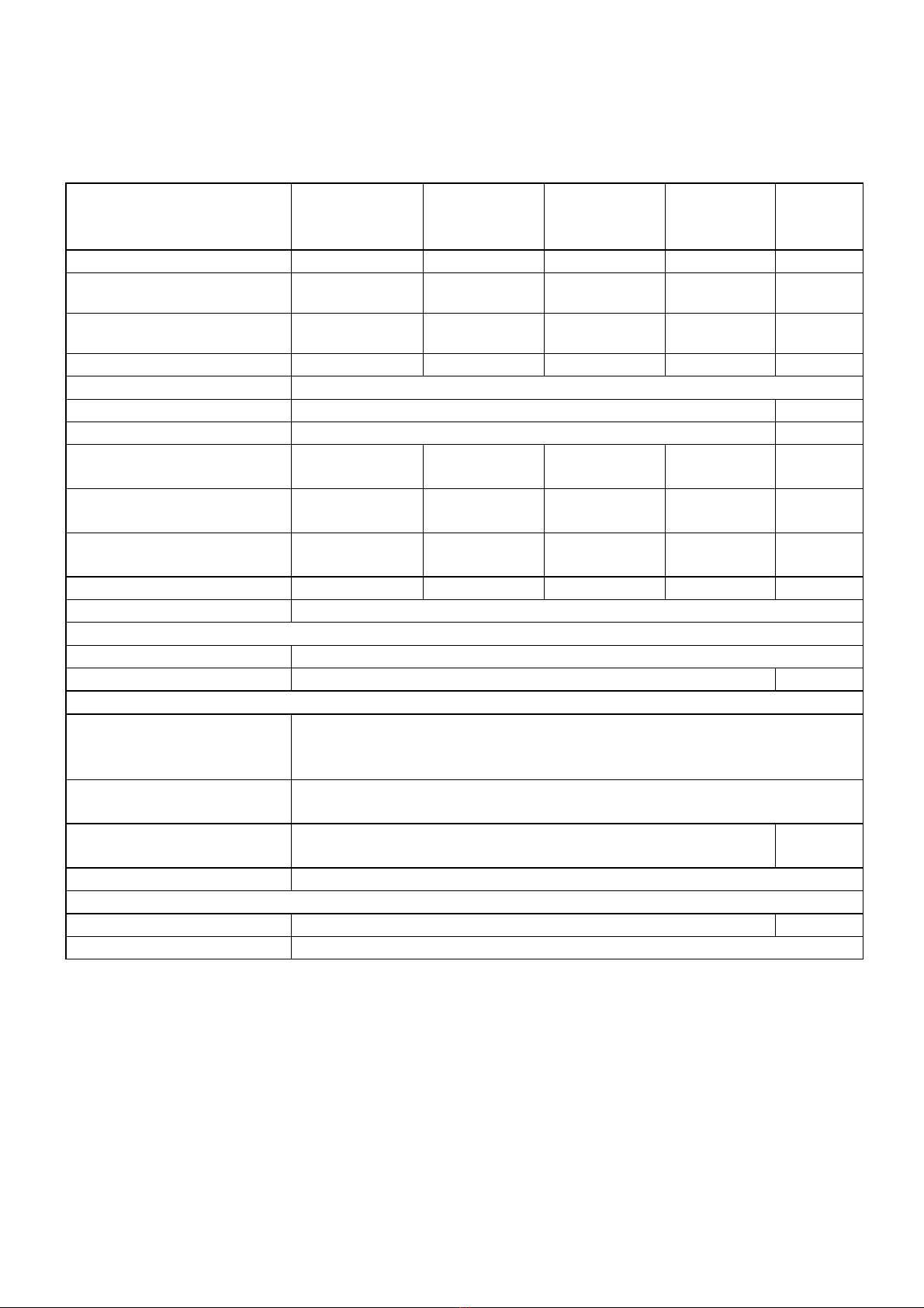
3. SPECIFICATIONS.....................................................................8
3.1 Product identification....................................................................... 8
3.2 Conformity to directives .................................................................. 8
3.3 Envisaged use................................................................................... 8
3.4 Technical specifications.................................................................. 9
4. INSTALLATION.......................................................................10
4.1 Checking on delivery...................................................................... 10
4.2 Choosing a place for installation .................................................. 11
4.3 Moving the unit............................................................................... 12
4.4 Mounting the module ..................................................................... 13
4.5 Electrical connection...................................................................... 13
4.6 Emissions from cooking appliance .............................................. 14
4.7 Checking before starting work...................................................... 15
5. WORKING ...............................................................................16
5.1 Description of controls .................................................................. 16
5.2 System functional states ............................................................... 17
5.2.1 Standby on/off button........................................................................17
5.3 Settings............................................................................................ 17
5.3.1 Set temperature setting ...............................................................17
5.3.2 Upper and lower element setting .....................................................17
5.3.3 Economy button ................................................................................18
5.3.4 Start/Stop button ...............................................................................18
5.3.5 Oven light button ...............................................................................18
5.3.6 Switch for suction hood ................................................................19
5.4 Programming .................................................................................. 19
5.4.1 Clock and day setting ................................................................................19
5.4.2 Baking cycle programming .......................................................................20
5.4.3 Auto switch-on programming ...................................................................21

_________________________________________________________________________INDEX
____________________________________________________________________________
4 CITIZEN 6 - 9/MC, CITIZEN 6+6 - 9+9/MC DIGITAL VERSION
5.4.4 Timer setting...............................................................................................22
5.5 Alarms ............................................................................................. 22
5.5.1 Overtemperature alarm..............................................................................22
6. THE USE OF THE OVEN ........................................................23
6.1 Preparation for use......................................................................... 23
6.2 Ignition of the control panel .......................................................... 23
6.3 Settings............................................................................................ 23
6.4 Baking start..................................................................................... 23
6.5 Loading the oven............................................................................ 23
6.6 General indications for good cooking.......................................... 24
6.7 Turning off....................................................................................... 24
7. CLEANING ..............................................................................26
7.1 Cleaning the exposed parts........................................................... 26
7.2 Cleaning the parts made from ceramic refractory material........ 26
7.3 Cleaning the oven's cooking chamber ......................................... 27
7.4 Cleaning external surfaces............................................................ 27
8. MAINTENANCE.......................................................................28
8.1 Ordinary maintenance work .......................................................... 28
8.1.1 Light replacement ......................................................................................28
8.2 Error displays.................................................................................. 28
8.3 Electrical diagram........................................................................... 29
8.4 Adjustment for different feed voltages......................................... 29
8.5 Exploded views and spare parts list............................................. 37
9. DECOMMISSIONING AND DEMOLITION..............................42
10. DECLARATION OF CONFORMITY......................................43

______________________________________________________________1. INTRODUCTION
____________________________________________________________________________
5 CITIZEN 6 - 9/MC, CITIZEN 6+6 - 9+9/MC DIGITAL VERSION
1. INTRODUCTION
The electrically fed baking modules of the "CITIZEN" oven series have been
designed mainly for the baking of pizzas and similar products in a traditional
way.
Of a high mechanical and electrical quality, the ovens of the "CITIZEN" series
are built with a single frame, in a version with one or two chambers and with
baking surfaces housing 6 or 9 pizzas having a 30 cm diameter.
As part of a modular series, these ovens can be combined with other
elements of the same range (hood, proofing chamber, base and base
modules), thus meeting each Customer's specific requests.
In particular the DIGITAL version, which we are referring to in this manual,
has been conceived to give our most demanding Customers a technological,
reliable, function-friendly oven, which are the features of an electronically
controlled oven.
The manufacturer wish to thank you for the preference you us by choosing
this product. We can assure you that you made a good choice, since for
decades our company has been committed to the manufacture of quality
products without compromises in the selection of the best materials.
For a better use of your new oven, we are asking you to follow the
instructions given in this manual.

____________________________________________________2. HOW TO USE THIS MANUAL
____________________________________________________________________________
6 CITIZEN 6 - 9/MC, CITIZEN 6+6 - 9+9/MC DIGITAL VERSION
2. HOW TO USE THIS MANUAL
The paragraphs with this symbol contain essential safety
information. They must all be read both by the installers and by the final
user and any of his staff who may use the equipment. The manufacturer
shall not be held liable for any damage which may occur as a result of
failure to observe the norms indicated in these paragraphs.
The paragraphs with this symbol contain important information
which can be used to avoid damage being caused to the equipment. It is
the user’s own interest also to read these paragraphs carefully.
This symbol applied to various points on the oven serves to warn
the user of danger: "ATTENTION HOT SURFACES!".
This symbol, applied to various points on the oven, serves to warn
the user of the presence of a non-insulated "high voltage hazard" inside
the oven's casing, there being enough power to constitute a fire risk or
to electrocute a person.
This manual should be kept near to the equipment itself so it can be
quickly and easily consulted. The manual must travel with the equipment if it
is moved to another owner as the latter may not be considered complete or
safe without it.
Please take note of the code and revision numbers which are behind the
back cover. If this copy should get mislaid or destroyed you can order
another one by referring to the codes.
This manual is divided up into a number of chapters. All of these should
be read by the installers, maintenance staff and the final user, both in
relation to its safe use and in order to obtain the best result from this product.
Despite this we also give below some useful indications on how to look things
up quickly in the various chapters.
Chapter 3 describes the field of use of the equipment and provides the
characteristics and figures which may be needed when choosing, installing
and using it. It should be used as a reference to check the use which is
intended to be made of the equipment corresponds to that for which it was
designed, and whenever it is necessary to know an exact size value relating
to the equipment.

____________________________________________________2. HOW TO USE THIS MANUAL
____________________________________________________________________________
7 CITIZEN 6 - 9/MC, CITIZEN 6+6 - 9+9/MC DIGITAL VERSION
Chapter 4 provides all the information necessary for the installation of the
equipment. The manual is primarily written for specialised staff but may be
read in advance also by the final user to prepare and set up the space and
plant necessary for the proper working of the equipment.
Chapter 5 is for reference whenever the user wishes to clarify specific
aspects of the equipment operation. It is not advisable to use these
chapters as a way to learn how to use the equipment.
Chapter 6 is useful for the user who has to learn to use the oven from
scratch. It guides the user through the essential operations for switching on,
use and switching off of the equipment in safety. To exploit all the possibilities
of the equipment the user should refer to chapter 5.
Chapter 7 provides all the information required for the cleaning of the
equipment i.e. all those operations which have to be carried out by the user in
order to ensure that the equipment continues to function safely (especially
from the point of view of hygiene) and generally obtains the best results at all
times.
Chapter 8 provides the information necessary for proper periodic and
extraordinary maintenance e.g. repairing or replacing of the equipment.
This chapter also has an exploded view of the equipment and list of spare
parts to make ordering and replacing any damaged parts easier.
These maintenance operations must be carried out by specialised staff.
Chapter 9 provides the information necessary for the decommissioning and
demolition.
Chapter 10 facsimile declaration of conformity.

_____________________________________________________________3. SPECIFICATIONS
____________________________________________________________________________
8 CITIZEN 6 - 9/MC, CITIZEN 6+6 - 9+9/MC DIGITAL VERSION
3. SPECIFICATIONS
3.1 Product identification
This manual refers to single chamber baking modules 6 - 9/MC and to double
chamber modules 6+6 - 9+9/MC of Citizen series, version with electronic
controls.
3.2 Conformity to directives
The above mentioned baking modules carry the following compulsory
marking:
which guarantees their conformity to the following European directives:
2004/108/CE electromagnetic compatibility;
2006/95/CE low voltage.
3.3 Envisaged use
The baking modules of the Citizen series have been designed to bake pizzas
and similar products and non fine pastry onto pans or directly on refractory
surfaces. Such modules are meant for a professional use only by qualified
personnel in the restaurant industry (restaurants, pizzerias, pastry shops,
etc.) and are exclusively intended to be used by qualified staff.
The operations envisaged in normal usage are the opening and closing of the
doors, the loading and unloading of the products from the bedplates of the
baking chamber, switching on, regulation, switching off and cleaning of the
equipment.

_____________________________________________________________3. SPECIFICATIONS
____________________________________________________________________________
9 CITIZEN 6 - 9/MC, CITIZEN 6+6 - 9+9/MC DIGITAL VERSION
3.4 Technical specifications
The following table shows the baking modules’ technical specifications.
Citizen
6/MC Citizen
6+6/MC Citizen
9/MC Citizen
9+9/MC
Units of
measure
ment
Weight 125 248 150 310 Kg
External dimensions 1370×960×
400 1370×960×
715 1370×1310×
400 1370×1310×
715 mm
Cooking chamber size 1050×700×
155 1050×700×
155 1050×1050×
155 1050×1050×
155 mm
Capacity (pizzas Ø30cm) 66+6 99+9 n°
Electrical feed three-phase or three-phase + neutral
Voltage 230 o 400 Vac
Frequency 50 o 60 Hz
Current at 400Vac
3-N 50/60Hz 13.9 26 16.55 33.1 A
Current at 230Vac
3 50/60Hz 24 48.2 28.6 57.2 A
Current at 230Vac
1-N 50/60Hz 38.3 76.5 48.7 97.4 A
Total electrical power 8.8 17.6 11.2 22.4 kW
Electrical connection plugless 4 or 5 lead cable
Cooking chamber light
Type halogen
Power 50 W
Cooking control
Temperature control
electromechanical
version electronic thermostat
Temperature control
electronic version electronic computerized
Maximum temperature
which can be set 400 °C
Power control separate for oven roof and bedplate
Ambient conditions
Temperature 0-40 °C
Maximum humidity 95% without condensation
Table 3.1.Technical specifications

_______________________________________________________________4. INSTALLATION
____________________________________________________________________________
10 CITIZEN 6 - 9/MC, CITIZEN 6+6 - 9+9/MC DIGITAL VERSION
4. INSTALLATION
ATTENTION: these installation instructions are for the
exclusive use of personnel qualified for the installation and
maintenance of electrical and gas equipment conceived for professional
use in the foodservice industry and community catering operations. An
installation carried out by unqualified persons could cause damage to
the oven, to people, animals or property.
ATTENTION: Proceed with the installation according to those
norms in force in the country where it is being carried out.
In addition, where it is necessary to carry out modifications or adaptations to
the electrical or gas systems of the building in which the oven will be
installed, whoever carries out such modifications must certify that the work
has been undertaken according to current “best practices”.
4.1 Checking on delivery
Unless otherwise agreed, the products are carefully packaged in a robust
structure in wood and with a sheet of nylon bubble wrap giving protection
against knocks and humidity during transport. These are consigned to the
freight operator in the best of condition.
We recommend, however, that you to check the packaging on arrival for
any signs of damage. If damage has occurred, have it noted on the receipt
which must be signed by the driver.
Once the equipment has been unpacked, check that it has not suffered
damage. Also check that all the dissembled parts are present.
In the event of damage to the equipment and/or missing parts, bear in mind
that the freight operator can only accept claims within 15 days of delivery and
that the manufacturer cannot be held responsible for damage incurred to its
products during their delivery. We are however, available to assist you in
presenting your claim.
In the event of damage do not try to use the equipment and
consult with professionally qualified personnel.

_______________________________________________________________4. INSTALLATION
____________________________________________________________________________
11 CITIZEN 6 - 9/MC, CITIZEN 6+6 - 9+9/MC DIGITAL VERSION
Figure 4.1.Cooling openings
4.2 Choosing a place for installation
An effective, safe and long lasting functioning of the appliance also
depends on the position in which it is installed. For this reason, it is advisable
to carefully consider where to install the equipment before it is delivered
Install the appliance in a dry and easily accessible place both to facilitate its
use and to carry out cleaning and maintenance. The area around the
equipment must be kept clear. It is particularly important to avoid obstructing
the cooling outlets located at the sides of the equipment.
The appliance must be installed
at least 20cm from the walls of the
room or from other equipment so that
the ventilation outlets located on the
sides of the oven are not obstructed.
Whilst in operation, cooking equipment
produces vapor and cooking smells that
compromise the integrity of a healthy
working environment
In the case of electric ovens, even if it is not obligatory, the installation
of an extraction fan and hood is recommended to improve conditions in the
working environment and to avoid damage to the ceiling of the area where it
is housed caused by hot, oily fumes.
A check must be made to ensure that the temperature and relative
humidity never exceed the maximum and minimum values indicted in the
specifications (see paragraph 3.4) even when the oven itself or other ovens
in the room are functioning.
Exceeding these values especially the temperature or the maximum
relative humidity can easily and unexpectedly damage electrical equipment
creating hazardous situations.
The manufacturer cannot answer for damage caused by ignoring
these abovementioned norms as well as the information in this manual.

_______________________________________________________________4. INSTALLATION
____________________________________________________________________________
12 CITIZEN 6 - 9/MC, CITIZEN 6+6 - 9+9/MC DIGITAL VERSION
Figure 4.2.Centre of gravity
4.3 Moving the unit
To offload and transport the unit, use a
pallet truck or a transpallet lifter with a
load capacity at least equal to that of the
unit, insert the forks into the space
provided in the lower part of the packing.
When moving the module which is not
packed insert the forks in the upper
chamber.
To avoid damage, place
protective material between the forks
and the unit.
In all situations, to avoid unpredictable movement, be aware of
the equipment’s centre of mass (Fig.4.2 e Tab.4.1).
Take care that children do not play with the packaging materials (
e.g., plastic sheeting and Styrofoam): suffocation danger!
a (mm) b (mm) c (mm)
Citizen 6/MC 685 455 200
Citizen 6+6/MC 685 455 357
Citizen 9/MC 685 630 200
Citizen 9+9/MC 685 630 357
Table 4.1.Centre of gravity

_______________________________________________________________4. INSTALLATION
____________________________________________________________________________
13 CITIZEN 6 - 9/MC, CITIZEN 6+6 - 9+9/MC DIGITAL VERSION
4.4 Mounting the module
Position the modules one above the other in the right order (prover or base,
baking module, hood) and fix by means of the accompanying hooks and
screws.
Figure 4.3.Position of electrical cable input, steam outlet and plate
4.5 Electrical connection
Before making any connection, check that the specifications of the
electrical supply to which the equipment must be connected, correspond to
the specifications of the power supply required by the apparatus itself (see
Tab. 3-1).
The appliances are supplied with an electric connection with
ground/earth cable for connecting the appliance to the power grid according
to the supply required (see cap. 3.4 Tab. 3.1).
In compliance with the safety norms in force. It is obligatory to connect the
ground/earth cable (yellow-green) to an earthing system with the same
a [mm] b [mm] c [mm] d [mm] w [mm]
Citizen 6/MC 740 630 733 400 1370
Citizen 6+6/MC 740 630 733 715 1370
Citizen 9/MC 740 630 1083 400 1370
Citizen 9+9/MC 740 630 1083 715 1370
steam outlet
electrical cable input

_______________________________________________________________4. INSTALLATION
____________________________________________________________________________
14 CITIZEN 6 - 9/MC, CITIZEN 6+6 - 9+9/MC DIGITAL VERSION
dispersion capacity as the appliance itself. The efficiency of this system
must be correctly verified according to the norms in force.
The power cable must terminate with a plug to connect to the electrical
switchgear having a corresponding differential magneto thermal switch.
The equipment is not supplied with a power plug.
The coupling between plug and socket must be such that the earth
conductor is connected first and disconnected last and must have the right
dimensions for the rated current (see Table 3-1). Plugs and sockets for
industrial use of the type CEE17 are suitable or those which satisfy European
norm EN 60309.
The thermal circuit breaker must be calibrated to the total rated current and
the magnetic circuit breaker calibrated to the rated current (In the case of
ovens this is only slightly higher than rated current), while the differential
mechanism must be calibrated to the 30 mA current (see Table 3-1).
The electrical socket must be easily accessible and must not require further
location after the installation of the equipment. The distance between the
equipment and the socket must be sufficient to avoid stretching the power
cable
The power cable must never be trapped under the feet or
wheels of the equipment
If the Power cable is damaged it must be substituted by
customer support or by a qualified service engineer so as to avoid
any risk.
The manufacturer does not accept responsibility for damage caused
by failure to observe the abovementioned norms.
For the position of the electrical power connections, see Fig. 4.3.
4.6 Emissions from cooking appliance
ATTENTION! Proceed with the installation of the oven according
to the norms defined by current legislation in the country concerning
the installation of this typology of oven so as to guarantee the
sustainability of a healthy working environment. For more information it
is recommended that specific norms be consulted.

_______________________________________________________________4. INSTALLATION
____________________________________________________________________________
15 CITIZEN 6 - 9/MC, CITIZEN 6+6 - 9+9/MC DIGITAL VERSION
The manufacturer cannot answer for damage caused by ignoring
these abovementioned norms as well as the information in this manual.
4.7 Checking before starting work
After completing installation of the unit a series of checks must be carried out,
listed as follows:
- check that the various disassembled parts have been assembled
- check the power cable
- check that the control panel is working
- If present, check that the ventilation hood is working
IMPORTANT - PRE-HEATING PHASE AT FIRST IGNITION
The components of the brand new oven (refractory stone bottom and metal
parts) need to be pre-heated before being used for the first baking.
When the oven is switched on the first time, it is necessary to HEAT IT
GRADUALLY IN ABOUT 5-6 HOURS (1°h=100°C - 2-3°h=150°C -
4°h=200°C - 5°h=250°C - 6°h=300°C). The max temperature has to be
reached at the end of this pre-heating phase.
This procedure is absolutely necessary to avoid damages to any part of the
oven.

_________________________________________________________________5. WORKING
____________________________________________________________________________
16 CITIZEN 6 - 9/MC, CITIZEN 6+6 - 9+9/MC DIGITAL VERSION
Fig. 6.1 Control panel
5. WORKING
5.1 Description of controls
Fig. 6.1 shows the control panel with all controls:
General system on/off button
Oven temperature and
time display
Set temperature display
Program setting increase
button
“Timer” - “Oven temperature”
– Clock setting” display button -
Program setting decrease
button
Upper element power setting
indicator
Upper element control display
Upper element power
sequential increase button
Lower element power setting
indicator
Lower element control display
Lower element power
sequential decrease button
Timer programming button
Baking cycle display
Baking cycle increase button
Oven light on/off
Baking start/stop button
Economy button
Light switch for suction hood

_________________________________________________________________5. WORKING
____________________________________________________________________________
17 CITIZEN 6 - 9/MC, CITIZEN 6+6 - 9+9/MC DIGITAL VERSION
5.2 System functional states
5.2.1 Standby on/off button
When on standby the panel is powered but no system function is enabled.
The general remote switch is disabled and the message OFF is displayed
on the set display on the control panel along with the current time
on the display with flashing seconds dot (between the second
and third figure, ½ second on, ½ second off).
All buttons on the panel are disabled except for the button (system on)
and the key, pressure on which will bring the system to clock setting
mode (see “programming” section).
Pressing the button, the system comes on, the last SET temperature
programmed is displayed on the set display , and the cycle used
prior to switching the oven off is displayed on the display.
5.3 Settings
5.3.1 Set temperature setting
To set the SET temperature use the and buttons until the desired
baking temperature appears on the display.
5.3.2 Upper and lower element setting
Pressing the buttons varies the time the oven heating elements remain
on. Each time the button is pressed increases this value by 1 unit, up to a
maximum of 9 units. Further pressure returns the value to 0.
NB. Each unit on the two displays corresponds to 5 seconds element on
time. For the remaining units the elements remain off. The total duration of
the cycle is 45 seconds.
The on time of the two elements can be varied at any time, even during the
baking cycle. The upper elements during the first part of the cycle while the
lower ones come on during the second.
For example, setting the upper elements to 6 and the lower ones to 5 gives
the following result:
5 10 15 20 25 30 35 40 45
Upper ON OFF
Lower OFF ON

_________________________________________________________________5. WORKING
____________________________________________________________________________
18 CITIZEN 6 - 9/MC, CITIZEN 6+6 - 9+9/MC DIGITAL VERSION
Note that with this setting, for the first 20 seconds only the upper elements
are on, so the oven uses half the total power. Over the next 10 seconds
both the upper and power elements are on, with the oven using full power.
In the remaining 15 seconds, on the lower elements are on, so the oven
once again uses half its available power.
5.3.3 Economy button
Pressing the economy button sets power values to pre-set levels
(upper 5 and lower 3) with the following result:
5 10 15 20 25 30 35 40 45
Upper ON OFF
Lower OFF ON
Note that with this setting, in the first 25 seconds only the upper elements
are on, with the oven using half power. Both elements are off for the
following 5 seconds. In the remaining 15 seconds only the lower elements
are on and so the oven once again uses only half power. This means that
throughout the cycle the oven never uses more than half power and for 5
seconds power consumption is zero.
A similar result can be obtained through manual power settings, if the sum
of upper and lower times is less than or at most equal to 9.
5.3.4 Start/Stop button
Pressing the start/stop button starts the baking cycle according to the
previous setting.
5.3.5 Oven light button
Pressing the oven light button switches on the light in the oven. Press
again to switch it off.

_________________________________________________________________5. WORKING
____________________________________________________________________________
19 CITIZEN 6 - 9/MC, CITIZEN 6+6 - 9+9/MC DIGITAL VERSION
5.3.6 Switch for suction hood
The switch for suction hood control
is placed on the side part of the control
panel, on the upper side (Pos.1 of Fig.
6.2).
Push this switch on position “I” to start one
of the two motors of the suction hood.
Push this switch on position “II” to start
both motors of the suction hood..
5.4 Programming
5.4.1 Clock and day setting
The time and day can only be set with the system on standby, that is to say
when the display “OFF”.
Pressing the key and holding it for 3 seconds displays the time on the
display with the two figures corresponding to the hour flashing.
The correct hour can be set using the and keys. To memorise the
new hour setting and pass on to setting minutes, press the key again.
The minutes start flashing and can be set in the same way as the hours.
Before pressing again, set the day of the week using the upper
element power sequence button . This displays the number
corresponding to the day on the upper element control display .
For example:
1=MONDAY
2=TUESDAY
3=WEDNESDAY
4=THURSDAY
5=FRIDAY
6=SATURDAY
7=SUNDAY
Pos.1
Fig 6.2

_________________________________________________________________5. WORKING
____________________________________________________________________________
20 CITIZEN 6 - 9/MC, CITIZEN 6+6 - 9+9/MC DIGITAL VERSION
Press again to memorise the new time and day. When set, the dot
between hours and minutes begins to flash and the day display disappears.
5.4.2 Baking cycle programming
To program the baking cycle the oven must be on. Press the general
system on/off button . The message “OFF” disappears from the
display and set temperature is displayed in its place.
In this condition, after selecting the desired cycle using the baking cycle
button and once the desired number for the cycle to memorise
appears on the display, press the timer programming button and
hold it for at least 3 seconds.
The displays show the following:
-Oven temperature and time display Prog
-Set temperature display Cic
-Upper element control display Off
-Lower element control display Off
-Baking cycle selection display No. of cycle
After 2 seconds, baking parameters can be modified according to needs.
The displays show the following:
- Oven temperature and time display Off
- Set temperature display Prev. set.
- Upper element control display Prev. set.
- Lower element control display Prev. set.
- Baking cycle selection display No. of cycle
Parameters that may be modified are:
1) Set temperature, by means of the and buttons;
2) Values corresponding to upper and lower power, by means of the
relative controls ,
3) The baking Timer; this parameter can be displayed on the
display by pressing the button, and subsequently modified by
means of the and buttons.
This manual suits for next models
4
Table of contents
Other ZANOLLI Kitchen Appliance manuals
Popular Kitchen Appliance manuals by other brands

Gastroback
Gastroback Design Tea & More Advanced operating instructions

Cuisinart
Cuisinart CSB-80 Instructions and recipes

CDA
CDA FWC152 Manual for installation, use and maintenance

Zanussi
Zanussi GC19 Instructions for the use & care

Scarlett
Scarlett SC-ET10D01 instruction manual

Tricity Bendix
Tricity Bendix SE500/1 user manual