manuals.online logo
Brands
  1. Home
  2. •
  3. Brands
  4. •
  5. Weslo
  6. •
  7. Elliptical Trainer
  8. •
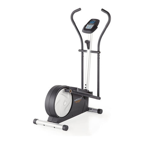
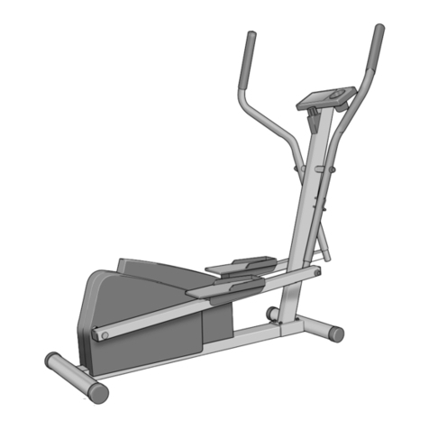
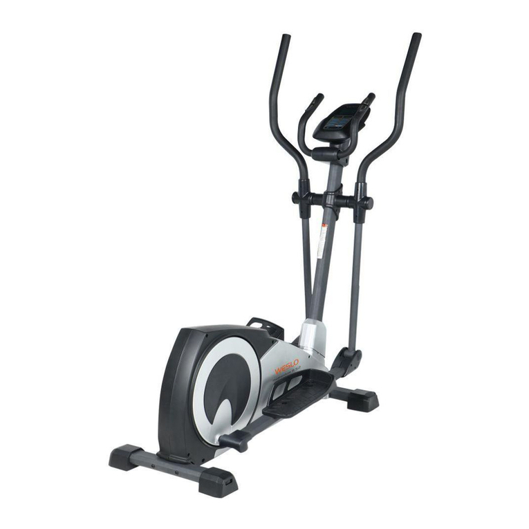
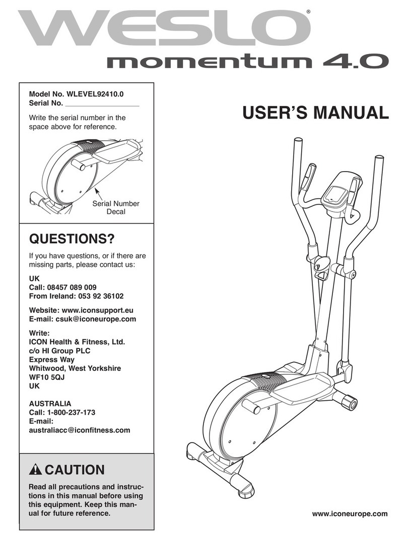
  9. Weslo Boomerang 850 Elliptical User manual

Weslo Boomerang 850 Elliptical User manual

This manual suits for next models

2

Other Weslo Elliptical Trainer manuals

Weslo WLEL32912.0 User manual

Weslo

Weslo WLEL32912.0 User manual

Weslo Momentum 615 Elliptical User guide

Weslo

Weslo Momentum 615 Elliptical User guide

Weslo Momentum 635 Elliptical User manual

Weslo

Weslo Momentum 635 Elliptical User manual

Weslo Momentum 750 Elliptical User manual

Weslo

Weslo Momentum 750 Elliptical User manual

Weslo Momentum 4.0 Elliptical Quick start guide

Weslo

Weslo Momentum 4.0 Elliptical Quick start guide

Weslo Momentum 620 Elliptical User manual

Weslo

Weslo Momentum 620 Elliptical User manual

Weslo Momentum 850 Elliptical User manual

Weslo

Weslo Momentum 850 Elliptical User manual

Weslo Momentum G 3.8 Elliptical User manual

Weslo

Weslo Momentum G 3.8 Elliptical User manual

Weslo Skier Plus WLUVSK10160 User manual

Weslo

Weslo Skier Plus WLUVSK10160 User manual

Weslo Momentum 4.0 Elliptical Setup guide

Weslo

Weslo Momentum 4.0 Elliptical Setup guide

Weslo Elliptical Glider 2.0 Operating and maintenance manual

Weslo

Weslo Elliptical Glider 2.0 Operating and maintenance manual

Weslo Momentum 7.0 Ex Elliptical User manual

Weslo

Weslo Momentum 7.0 Ex Elliptical User manual

Weslo Momentum 4.8 Elliptical User manual

Weslo

Weslo Momentum 4.8 Elliptical User manual

Weslo Momentum 4.0 Elliptical User manual

Weslo

Weslo Momentum 4.0 Elliptical User manual

Weslo Momentum 410 Elliptical User manual

Weslo

Weslo Momentum 410 Elliptical User manual

Weslo Body Shop 9 User manual

Weslo

Weslo Body Shop 9 User manual

Weslo EasyFit WLIVEL86172.0 User manual

Weslo

Weslo EasyFit WLIVEL86172.0 User manual

Weslo Momentum 410 Elliptical User manual

Weslo

Weslo Momentum 410 Elliptical User manual

Weslo Momentum 410 Elliptical Operating and maintenance manual

Weslo

Weslo Momentum 410 Elliptical Operating and maintenance manual

Weslo WLEVEL28010 User manual

Weslo

Weslo WLEVEL28010 User manual

Weslo Momentum G 3.2 Elliptical User manual

Weslo

Weslo Momentum G 3.2 Elliptical User manual

Weslo Momentum 220X WLEL2006.0 User manual

Weslo

Weslo Momentum 220X WLEL2006.0 User manual

Weslo EasyFit WLIVEL0063.1 User manual

Weslo

Weslo EasyFit WLIVEL0063.1 User manual

Weslo WLEL28020 User manual

Weslo

Weslo WLEL28020 User manual

Popular Elliptical Trainer manuals by other brands

NordicTrack AudioStrider 990 PRO NTEL09811.2 user manual

NordicTrack

NordicTrack AudioStrider 990 PRO NTEL09811.2 user manual

Progear Fitness Air elliptical pro 1307 owner's manual

Progear Fitness

Progear Fitness Air elliptical pro 1307 owner's manual

Torque Fitness XPLLP owner's manual

Torque Fitness

Torque Fitness XPLLP owner's manual

Octane Fitness PRO3700C Operation manual

Octane Fitness

Octane Fitness PRO3700C Operation manual

Xterra FS5.8e owner's manual

Xterra

Xterra FS5.8e owner's manual

Bodyguard E-40 user manual

Bodyguard

Bodyguard E-40 user manual

Vision Fitness X6600iNetTV Assembly guide

Vision Fitness

Vision Fitness X6600iNetTV Assembly guide

NordicTrack E 7.2 Elliptical null

NordicTrack

NordicTrack E 7.2 Elliptical null

NordicTrack E4.1 Elliptical null

NordicTrack

NordicTrack E4.1 Elliptical null

NordicTrack E4.1 Elliptical null

NordicTrack

NordicTrack E4.1 Elliptical null

Pro-Form 690 Hr Elliptical null

Pro-Form

Pro-Form 690 Hr Elliptical null

Pro-Form 800 Hr Heart Rate Control Elliptical null

Pro-Form

Pro-Form 800 Hr Heart Rate Control Elliptical null

Bonn Germany Concept 2.2 user manual

Bonn Germany

Bonn Germany Concept 2.2 user manual

Precor Resolute RSL 620 Assembly guide

Precor

Precor Resolute RSL 620 Assembly guide

NordicTrack E 9.2 Elliptical HASZNALATI UTASITAS

NordicTrack

NordicTrack E 9.2 Elliptical HASZNALATI UTASITAS

Sears FREE SPIRIT C249 30737 0 owner's manual

Sears

Sears FREE SPIRIT C249 30737 0 owner's manual

True FS-64 Assembly manual

True

True FS-64 Assembly manual

Sport-thieme ST 310 manual

Sport-thieme

Sport-thieme ST 310 manual

manuals.online logo
manuals.online logoBrands
  • About & Mission
  • Contact us
  • Privacy Policy
  • Terms and Conditions

Copyright 2025 Manuals.Online. All Rights Reserved.

CAUTION
Read all precautions and instruc-
tions in this manual before using
this equipment. Keep this manu-
al for future reference.
Model No. WLEVEL28840
Serial No.
QUESTIONS?
As a manufacturer, we are com-
mitted to providing complete cus-
tomer satisfaction. If you have
questions, or if there are missing
or damaged parts, please call:
Fax: 0034 91 661 98 32
E-mail: serviciotecni-
co@bahnli.com
USERʼS MANUAL
Serial Number
Decal
0034 91 661 02 10
TABLE OF CONTENTS
MPORTANTPRECAUTONS .................................................................3
BEFOREYOUBEGN .......................................................................4
ASSEMBLY ...............................................................................5
HOWTOUSETHEELLPTCALCROSSTRANER ................................................9
MANTENANCEANDTROUBLESHOOTNG ....................................................12
CONDTONNGGUDELNES ...............................................................13
PARTLST ...............................................................................14
EXPLODEDDRAWNG .....................................................................15
HOWTOORDERREPLACEMENTPARTS..............................................BackCover
2
3
IMPORTANT PRECAUTIONS
WARNING: To reduce the risk of serious injury, read the following important precau-
tions before using the elliptical crosstrainer.
1. Read all instructions in this manual before
using the elliptical crosstrainer. Use the
elliptical crosstrainer only as described.
2. It is the responsibility of the owner to
ensure that all users of the elliptical
crosstrainer are adequately informed of all
precautions.
3. Place the elliptical crosstrainer on a level
surface, with a mat beneath it to protect the
floor or carpet. Keep the elliptical crosstrain-
er indoors, away from moisture and dust.
4. Inspect and properly tighten all parts regu-
larly. Replace any worn parts immediately.
5. Keep children under 12 and pets away from
the elliptical crosstrainer at all times.
6. The elliptical crosstrainer should not be
used by persons weighing more than 115 kg
(250 lbs.).
7. Wear appropriate exercise clothing when
using the elliptical crosstrainer. Always wear
athletic shoes for foot protection.
8. Always hold the handlebars when mounting,
dismounting, or using the elliptical
crosstrainer.
9. Keep your back straight when using the
elliptical crosstrainer. Do not arch your
back.
10. The pulse sensor is not a medical device.
Various factors may affect the accuracy of
heart rate readings. The pulse sensor is
intended only as an exercise aid in determin-
ing heart rate trends in general.
11. If you feel pain or dizziness at any time whilst
exercising, stop immediately and cool down.
12. When you stop exercising, allow the pedals
to slowly come to a stop.
13. The elliptical crosstrainer is intended for
home use only. Do not use the elliptical
crosstrainer in a commercial, rental, or insti-
tutional setting.
14. A warning decal has been placed on the
elliptical crosstrainer in the location shown
below. Please note that the text on the decal
is in Spanish. Find the decal in English and
place it over the Spanish decal.
If the decal is missing, or if it is not legible,
please please call our Customer Service
Department and order a free replacement
decal (see the back cover of this manual).
Apply the decal in the location shown.
WARNING: Before beginning this or any exercise program, consult your physician.
This is especially important for persons over the age of 35 or persons with pre-existing health prob-
lems. Read all instructions before using. ICON assumes no responsibility for personal injury or
property damage sustained by or through the use of this product.
4
BEFORE YOU BEGIN
Congratulations for selecting the new BOOMERANG
850 elliptical crosstrainer. The BOOMERANG 850
elliptical crosstrainer is an incredibly smooth exerciser
that moves your feet in a natural elliptical path, mini-
mizing the impact on your knees and ankles. And the
unique BOOMERANG 850 features adjustable resis-
tance and a simple-to-use console to help you get the
most from your exercise.
For your benefit, read this manual carefully before
using the elliptical crosstrainer. f you have ques-
tions after reading this manual, please call our
Customer Service Department at 0034 91 661 02 10.
To help us assist you, please note the product model
number and serial number before calling. The model
number is WLEVEL28840. The serial number is found
on a decal attached to the elliptical crosstrainer (see
the front cover of this manual for the location of the
decal).
Before reading further, please familiarise yourself with
the parts that are labeled in the drawing below.
Handlebar
FRONT
BACK Pedal Arm
Pedal Disk
*No water bottle is included
Pedal
Console
Water Bottle Holder*
Pulse Sensor
Resistance Knob
Wheel
ASSEMBLY
Assembly requires two persons. Place all parts of the elliptical crosstrainer in a cleared area and remove the
packing materials. Do not dispose of the packing materials until assembly is completed. In addition to the
included hex keys, assembly requires a phillips screwdriver , an adjustable
spanner , and a rubber mallet .
As you assemble the elliptical crosstrainer, use the drawings below to identify the small parts used in assembly.
The number in parenthesis below each drawing refers to the key number of the part, from the PART L ST on
page 14. The second number refers to the quantity used in assembly. Note: Some small parts may have been
pre-assembled for shipping. If a part is not in the parts bag, check to see if it has been pre-assembled.
5
M8
Washer (48)–4
M8 Split
Washer (59)–6
M8 Nylon
Locknut (38)–8 M10
Washer (35)–2
M4 x 16mm
Screw (42)–5
M10 x 25mm
Patch Screw (22)–2
M6 x 48mm Flat Head
Screw (36)–4
Pedal Arm Bolt Set (40)–2
M8 x 38mm Button Bolt (50)–4
M8 x 25mm Button
Screw (45)–1
M8 x 19mm Button
Screw (68)–6
M8 x 53mm Button Bolt (34)–4
1. dentify the Front Stabiliser (10), which is narrower than
the Rear Stabiliser (not shown). Whilst another person
lifts the front of the Frame (1), attach the Front
Stabiliser to the Frame with two M8 x 53mm Button
Bolts (34), two M8 Washers (48), and two M8 Nylon
Locknuts (38).
10
38
34
1
48
48
1
6
2. Whilst another person lifts the back of the Frame (1),
attach the Rear Stabiliser (28) to the Frame with two
M8 x 53mm Button Bolts (34), two M8 Washers (48),
and two M8 Nylon Locknuts (38).
34
28
48
48
1
2
38
3. nsert the Console Bracket (63) into the Upright (2) as
shown. Attach the Console Bracket to the Upright with
an M8 x 25mm Button Screw (45), two M8 Split
Washers (59), and two M8 x 19mm Button Screws
(68).
4. The Console (23) requires three 1.5V “AA” batteries;
alkaline batteries are recommended. nsert three bat-
teries into the battery compartment. Make sure that
the batteries are oriented as shown by the diagram
inside the battery compartment.
63
45
59
68
59
68
2
3
5. Have another person hold the Console (23) in the
position shown. nsert the control cable down through
the Upright (2). Connect the console wire to the Upper
Wire (44). Attach the ground wire to the Console
Bracket (63) with an M4 x 16mm Screw (42). Next,
insert the excess cable and wire down into the Upright.
Attach the Console (23) to the Console Bracket (63)
with four M4 x 16mm Screws (42). Be careful to
avoid pinching the cable and wires.
Make sure that the resistance knob is turned to the
lowest setting before continuing.
4
23
23
5
Batteries
63
42
2
42
Control Cable
Resistance
Knob
Console Wire
Ground
Wire
44
50
38
7
7. dentify the Left Handlebar (6), which is marked with a
sticker. nsert the Left Handlebar into one of the
Handlebar Arms (5); make sure that the Handlebar
Arm is turned so the hexagonal holes are on the
indicated side. Attach the Left Handlebar to the
Handlebar Arm with two M8 x 38mm Button Bolts (50)
and two M8 Nylon Locknuts (38). Make sure that the
Nylon Locknuts are inside of the hexagonal holes.
Do not fully tighten the Button Bolts yet.
Apply a small amount of the included grease to the left
axle on the Upright (2).
Make sure that there are two Small Handlebar
Bushings (49) in the Left Handlebar (6). Slide a
Handlebar Spacer (47) and the Left Handlebar onto the
left axle on the Upright (2) as shown. Make sure that the
Handlebar Spacer is turned so the curved side is fac-
ing the Upright. Tap an Axle Cap (14) onto the axle.
Repeat this step to assemble the Right Handlebar (8)
and the other Handlebar Arm (5).
Grease
7
47
14
49
5
2
5
6
8
Hexagonal
Holes
6
1
2
68
68Make sure that
the wires and
cables do not
get pinched
and damaged
during this
step.
44
53
68
55
59
59
59
6. Whilst another person holds the Upright (2) near the
Frame (1), connect the Upper Wire (44) to the Reed
Switch Wire (53).
Next, connect the control cable to the Lower Cable
(55) in the following way:
• See drawing A. Pull up on the metal bracket on the
Lower Cable (55), and insert the tip of the control
cable into the wire clip inside of the metal bracket.
• See drawing B. Firmly pull the control cable and
slide it into the metal bracket on the Lower Cable
(55) as shown.
• See drawing C. Using pliers, squeeze together the
prongs on the upper end of the metal bracket.
Push the excess cable and wire down into the Frame
(1). Slide the Upright (2) onto the Frame. Be careful
not to pinch the wires or cables. Attach the Upright
with four M8 x 19mm Button Screws (68) and four M8
Split Washers (59). Do not tighten the Button
Screws yet.
55 55
Metal
Bracket
B
AC
55
Control
Cable
Control
Cable
Control
Cable
Control
Cable
8
10. Make sure that all parts of the elliptical crosstrainer are properly tightened. Note: Some hardware may
be left over after assembly is completed. To protect the floor or carpet from damage, place a mat under the
elliptical crosstrainer.
9. Apply a small amount of grease to the axle on the left
Disc Crossbar (16). Slide the Left Pedal Arm (11) onto
the axle. Slide an M10 Washer (35) onto an M10 x
25mm Patch Screw (22), and tighten the Patch Screw
into the axle.
Next, hold the lower end of the left Handlebar Arm (5)
inside of the bracket on the Left Pedal Arm (11). Apply
grease to a Pedal Arm Bolt Set (40). Attach the Left
Pedal Arm to the left Handlebar Arm with the Bolt Set.
Do not overtighten the Bolt Set; the Handlebar Arm
must pivot freely.
Attach the Right Pedal Arm (12) to the right side of the
elliptical crosstrainer in the same way.
See step 5. Tighten the M8 x 19mm Button Screws (68)
in the Upright (2).
See step 6. Tighten the M8 x 38mm Button Bolts (50)
in the Handlebar Arms (5).
Grease
22 35
11
12
5
9
40
40
8
36
11
13
8. dentify the Left Pedal Arm (11). Attach a Pedal (13) to
the Left Pedal Arm with two M6 x 48mm Flat Head
Screws (36) as shown.
Attach the other Pedal to the Right Pedal Arm (not
shown) in the same way.
Grease
16
9
HOW TO USE THE ELLIPTICAL CROSSTRAINER
HOW TO EXERCISE ON THE ELLIPTICAL
CROSSTRAINER
To mount the elliptical crosstrainer, hold the handlebars
and step onto the pedal that is in the lowest position.
Then, step onto the other pedal. Push the pedals until
they begin to move with a continuous motion. Note:
The pedal disks can turn in either direction. It is
recommended that you move the pedal disks in
the direction shown by the arrow; however, for
variety, you may turn the pedal disks in the oppo-
site direction.
To dismount the elliptical crosstrainer, wait until the
pedals come to a complete stop. Note: The elliptical
crosstrainer does not have a free wheel; the ped-
als will continue to move until the flywheel stops.
When the pedals are stationary, step off the highest
pedal first. Then, step off the lowest pedal.
HOW TO AD UST THE PEDALING RESISTANCE
As you exercise,
you can adjust the
resistance of the
pedals with the
resistance knob
on the console. To
increase the resis-
tance, turn the
knob clockwise; to
decrease the
resistance, turn the knob counterclockwise.
FEATURES OF THE CONSOLE
The easy-to-use console is designed to help you get
the most from your workouts. As you exercise, the
console will display the following modes:
Time—This mode displays the elapsed time (or the
time remaining in a pace program). Note: f you stop
pedalling, the time will begin to flash.
Distance—This mode displays the distance that you
have pedalled.
Calories—This mode displays the approximate number
of calories you have burned.
Fat calories—This mode displays the approximate
number of fat calories you have burned (see FAT
BURN NG on page 13).
Pulse—This mode displays your heart rate when you
use the pulse sensor.
Speed—This mode displays your pedalling speed.
Scan—When this mode is selected, the upper section
of the display will show both the speed mode and the
distance mode, and the lower left section of the display
will show both the calories mode and the fat calories
mode.
The console also offers four pace programs. Each pro-
gram automatically prompts you to increase or
decrease your pace as it guides you through an effec-
tive workout.
Pedal Disk
Pedal
Resistance
Knob
10
HOW TO USE THE MANUAL MODE
Turn on the console.
To turn on the console, press the On/Reset button
or begin pedalling. Note: f there is a sheet of clear
plastic on the console, remove it.
Select the manual mode.
Each time the
console is
turned on, the
manual mode
will be select-
ed. f a pace
program has
been selected,
reselect the
manual mode by pressing the Program button
repeatedly until the upper right corner of the dis-
play is blank.
Begin pedalling and adjust the resistance of
the pedals.
As you exercise, adjust the resistance of the ped-
als as desired by turning the resistance knob.
Follow your progress with the display.
When the con-
sole is turned
on, the scan
mode will be
selected, as
shown by the
mode bar
below the word
“SCAN.” As
you exercise,
the upper sec-
tion of the dis-
play will alternately show the elapsed time and the
distance that you have pedalled; the lower left
section of the display will alternately show the
number of calories you have burned and the num-
ber of fat calories you have burned; and the lower
right section will show your pedalling speed.
n addition, the pace indicator on the right side of
the display will provide a visual representation of
your pedalling pace. As you increase or decrease
your pace, the indicator will increase or decrease in
height.
To cancel the scan mode, press the Mode button.
The mode bar
below the word
“SCAN” will dis-
appear. The
upper section of
the display will
then show only
the elapsed
time, and the
lower left section of the display will show only the
number of calories you have burned. Press the
Mode button again. The upper section of the dis-
play will then show only the distance pedalled,
and the lower left section of the display will show
only the number of fat calories you have burned.
To select the scan mode again, press the Mode
button repeatedly until a mode bar appears below
the word “SCAN.”
To reset the display, press the On/Reset button.
Note: The console can show speed and dis-
tance in either miles or kilometers. To change
the unit of measurement, hold down the
On/Reset button for about six seconds. When
the batteries are replaced, it may be necessary
to reselect the desired unit of measurement.
Measure your heart rate if desired.
Note: If there
are thin sheets
of plastic on the
metal contacts
of the pulse
sensor, peel off
the plastic.
To use the pulse sensor, hold the handle on the
console, with your right palm covering the two
right contacts and your left palm covering the two
left contacts. Avoid moving your hands. When
your pulse is detected, the heart-shaped indicator
in the display will flash each time your heart beats
and two dashes (– –) will appear. After a moment,
your heart rate will be shown. For the most accu-
rate heart rate reading, continue to hold the hand-
grips for about 15 seconds.
When you are finished exercising, the console
will automatically turn off after a few minutes.
f the pedals are not moved and the console but-
tons are not pressed for a few minutes, the con-
sole will automatically turn off to conserve the
batteries.
6
5
4
3
2
1
This corner
should be blank
Pace ndicator
Mode Bar
Contacts
Handle