First Light C-BLUE One User manual
C-BLUE One
User Manual
C-BLUE One User Manual_20211129

2
TABLE
1. INTRODUCTION........................................................................................................................ 6
Overview............................................................................................................................ 6
Caution.............................................................................................................................. 7
2. READ BEFORE USE..................................................................................................................8
General warnings..............................................................................................................8
Never open your camera .................................................................................................. 8
Power circuitry..................................................................................................................8
Cooling water....................................................................................................................8
Symbols and Indications...................................................................................................9
Disposal - DEEE................................................................................................................ 9
3. CAMERA DELIVERY ................................................................................................................ 10
Package content ............................................................................................................. 10
Resources....................................................................................................................... 11
Test report............................................................................................................... 11
Additional resources ............................................................................................... 11
4. SPECIFICATIONS.................................................................................................................... 12
Operating conditions....................................................................................................... 12
Storage conditions.......................................................................................................... 12
Sensor specifications...................................................................................................... 12
Global shutter and IWR................................................................................................... 13
Quantum efficiency curve ............................................................................................... 14
Angular acceptance ........................................................................................................ 14
Main camera features..................................................................................................... 15
5. THERMAL MANAGEMENT...................................................................................................... 16
Sensor thermal management ........................................................................................ 16
Camera thermal management ....................................................................................... 16
Overview .................................................................................................................. 16
Optional water-cooled plate.................................................................................... 16
Thermal performances ........................................................................................... 17
Electronics protection ............................................................................................. 18
6. MECHANICS ........................................................................................................................... 19
Overview.......................................................................................................................... 19

3
Mechanical drawings.......................................................................................... 19
7. CAMERA INTERFACES........................................................................................................... 24
Back face overview ......................................................................................................... 24
Camera status LEDs....................................................................................................... 24
Power supply .................................................................................................................. 25
Via PoCXP ................................................................................................................ 25
External power supply............................................................................................. 25
CoaXPress®interface ..................................................................................................... 26
Ethernet interface........................................................................................................... 26
I/O port............................................................................................................................ 26
8. CoaXPress®............................................................................................................................ 29
Overview.......................................................................................................................... 29
Recommended frame grabbers ..................................................................................... 30
CoaXPress®communication........................................................................................... 30
Configuration........................................................................................................... 30
Connectors .............................................................................................................. 31
Cable lengths........................................................................................................... 31
Connector Indicator lamps...................................................................................... 31
CoaXPress® supported functionalities................................................................... 32
Power-over-CoaXPress®......................................................................................... 32
9. SETTING UP AND STARTING UP CAMERA ............................................................................ 33
Configuring your computer............................................................................................. 33
Recommended system requirements..................................................................... 33
Software installation....................................................................................................... 33
First Light Imaging Graphical User Interface software.......................................... 33
Software Development Kit....................................................................................... 34
Quick start....................................................................................................................... 34
Powering ON & camera connection........................................................................ 34
Powering OFF & camera disconnection.................................................................. 34
Camera storage....................................................................................................... 34
10. CAMERA FUNCTIONALITIES.................................................................................................. 35
Device control ................................................................................................................. 35
Basic device information ......................................................................................... 35
Basic device control ................................................................................................ 36
Temperature control ............................................................................................... 36

4
Acquisition Control ............................................................................................. 36
Basic commands ..................................................................................................... 36
Integration time and framerate............................................................................... 37
Image correction ..................................................................................................... 38
Trigger mode........................................................................................................... 38
AcquisitionStart................................................................................................ 39
AcquisitionEnd ................................................................................................. 40
FrameBurstStart.............................................................................................. 41
FrameBurstStart + FrameBurstEnd................................................................ 42
FrameStart....................................................................................................... 43
ExposureStart/ExposureEnd............................................................................ 44
Trigger timings................................................................................................. 47
Basic Image Format Control .......................................................................................... 49
Sensor format.......................................................................................................... 49
Pixel bit depth.......................................................................................................... 50
Analog control................................................................................................................. 50
Conversion efficiency............................................................................................... 50
Analog and digital gains .......................................................................................... 50
Black level adjustment............................................................................................ 51
Camera presets .............................................................................................................. 51
Region of interests.......................................................................................................... 52
Single ROI support................................................................................................... 52
Multiple ROI support ............................................................................................... 53
Impact of the ROI on the acquisition frame rate ..................................................... 57
11. CAMERA MAINTENANCE....................................................................................................... 58
Troubleshooting.............................................................................................................. 58
Pattern Generation ......................................................................................................... 60
Firmware update ............................................................................................................ 61
Cleaning of the window................................................................................................... 61
Support requests ............................................................................................................ 62
12. PRECAUTIONS & PRODUCT SAFETY..................................................................................... 63
Precaution of use............................................................................................................ 63
Environmental conditions........................................................................................ 63
Static & electric shocks........................................................................................... 63
Never open the camera........................................................................................... 63

5
13. WARRANTY AND LIABILITY........................................................................................ 64
For the USA..................................................................................................................... 64
Limited Warranty..................................................................................................... 64
Conditions................................................................................................................ 64
Warranty Enforcement............................................................................................ 64
Returns.................................................................................................................... 65
Liability Upon Delivery ..................................................................................... 65
Products Offered “As Is”.................................................................................. 65
No Other Warranties........................................................................................ 65
Limitation of Liability........................................................................................ 65
Purchaser Warranties............................................................................................. 65
Purchaser Indemnification...................................................................................... 65
For the rest of the World ................................................................................................ 66
FLI’s legal guarantee and limit to the guarantee.................................................... 66
FLI’s liability ............................................................................................................ 66
Liability in connection with defective products ....................................................... 66
14. CONTACT US .......................................................................................................................... 67
For the USA..................................................................................................................... 67
For the rest of the world................................................................................................. 67

6
1. INTRODUCTION
Thank you for choosing C-BLUE One!
C-BLUE One features and performances are described in detail within this User Manual.
This User Manual contains all information and advice needed to get the optimum performance from C-
BLUE One.
You can also find an up-to-date version of this User Manual on our website: https://www.first-light-
imaging.com/user-manuals/
Please contact our support for any question at: support@first-light.fr
Overview
C-BLUE One (formerly C-MORE) is a range of high-performance scientific cameras based on Sony
CMOS sensors IMX425LLJ-C, IMX426LLJ-C and IMX420LLJ-C.
However, the IMX420LLJ-C is not supported yet (planned for 2022).
The information relative to this sensor will be added to this manual when the camera integrating this
sensor is available.
Quantization is done with 8 bits or 12 bits for all versions, but the resolution and the maximum
framerates of the sensors are different.
Sensor Resolution
Width x Height
(pixels)
Pixel size
(µm)
FPS max 8 bits FPS max 12 bits
IMX425
1608 x 1104
9 x 9
662
481
IMX426
816 x 624
9 x 9
1594
941
The camera uses CoaXPress®2.0 to transfer the massive amount of data generated each second to
ensure the lowest latency and highest real time capability.
A key feature of the camera to enable artefact-free acquisitions in dynamic imaging is the global shutter
mode. Additionally, the readout noise is lower than 3 electrons in 12 bits quantization.
With C-BLUE One, simultaneously and for the first time a global shutter architecture and low noise is
made possible, which is a major improvement for fast acquisition scientific applications.
C-BLUE One opens new horizons for low noise high speed visible imaging.
This release of the manual describes the features available in the firmware version 1.3.0.

7
Caution
This User Manual describes precisely how to handle your material properly and to avoid accidents.
Please follow the instructions of use to take advantage of all C-BLUE One performances.
Please carefully read the warnings (section 2) and follow the safety precautions to avoid any personal
injury or damage when using the camera.
C-BLUE One contains fragile components.
Always follow the instructions of use.

8
2. READ BEFORE USE
General warnings
The equipment must be plugged on an electrical wiring compliant with the relevant standards in the
country (in France: NFC 15-100). This wiring must be protected from overcurrent, overvoltage, and
ground defaults.
Connected equipment’s must be compliant with the EN 60950-1 Ed.2006 standard, or to their own
standards.
The power cable plug serves as a disconnection device and should be easily accessible.
Do not place the equipment close to a heating source or a humidity source.
The security of the system which integrates the equipment is the responsibility of the system assembler
only.
For your safety, the equipment must be TURNED OFF AND UNPLUGGED before any technical
intervention.
The security provided with this equipment is only guaranteed with a use in accordance with the specified
purpose. Only use the provided (MEAN WELL USA Inc, model GST60A12-P1J) power supply.
Never open your camera
Do not ever attempt to open your camera. There are indicators inside the camera, if you try to open it
your warranty will be void.
Do not open the camera: the warranty will be void.
Power circuitry
Use the camera with the voltage indicated. Using a different voltage may damage your camera and lead
to fire or electric shock.
Always use the supplied power unit.
Cooling water
If you are using the cooling plate adaptor, be sure that the cooling system is correctly connected before
turning on the camera and check that no leaks are visible.
The camera’s electronics will be permanently damaged if water leaks inside the
camera.

9
Symbols and Indications
Please read this User Manual and the following definitions carefully to understand the potential
dangers and the precautions to take.
Please refer to this User Manual if a WARNING symbol is marked on the camera.
The CE marking indicates the conformity of the camera to the European legislation.
This pictogram indicates a direct current operation.
This pictogram invites the user to refer to the instructions / user manual.
This pictogram refers to indoor use.
This pictogram refers to Protection class category 1.
This pictogram indicates that the product is compliant with the RoHS limitation.
Disposal - DEEE
DO NOT throw the camera in municipal waste. This symbol of the crossed out wheeled bin
indicates that the product (electrical and electronic equipment) should not be placed in
municipal waste. Check local regulations for disposal of electronic products.
DO NOT throw the Li-ion button cell battery in municipal waste. This symbol of the crossed out
wheeled bin indicates that the battery should not be placed in municipal waste.
In case of disposal, do not throw your camera in a waste disposal, you can send it back
to First Light Imaging.

10
3. CAMERA DELIVERY
Package content
Your C-BLUE One camera will be delivered in a hard Pelicase, with the following components:
Table 1 – Package items description
Accessories can be ordered separately. Please contact your sales representatives for details and
pricing of the items and accessory packs. Other references may be compatible, with respect of the
minimum requirements (refer to section 9.1.1).
Table 2 - Optional items (can be bought separately)
On the left, closed Pelicase®. On the right, opened Pelicase® with dedicated spaces*.
* Items may differ from pictures.
Items
Number
Camera
1
Power supply
1
Power supply cable (IEC / NEMA / other)
1
C-Mount adapter
1
Press button tool (cf. rescue software)
1
Quick Start Manual
1
USB key (User manual, software and camera test report)
1
Items
Number
CoaXPress
®
cable
2
Cooling plate
1
Cooling unit
1
Personal computer
1

11
Resources
Test report
The performances of your camera have been evaluated by First Light Imaging to ensure the compliance
with our standards. The Test Report is available in the USB key delivered with the camera.
Additional resources
Additional resources, such as technical notes, user manuals, latest software releases, white papers,
etc. are available online. As a customer of First Light Imaging, you can create a personal account on
the website www.first-light-imaging.com and have access to “Your library”, as specific directory with
all the documents concerning your camera.
Table 3 – List of additional resources
If you have inquiries, do not hesitate to contact us.
For technical support: support@first-light.fr
For commercial support: contact@first-light.fr
Items
URL
Download latest software release
Your library
Download latest firmware upgrade
Your library
3D CAD files
Your library
Technical papers
Your library
C-BLUE One product page on the website
C-BLUE ONE - FirstLight (first-light-imaging.com)
12
4. SPECIFICATIONS
Operating conditions
The operating conditions of C-BLUE One are as follows. Do not operate the camera beyond these
environmental specifications, as this may cause damage to the camera.
Table 4 – C-BLUE One operating conditions
Storage conditions
To avoid damaging the camera and altering its performances, the camera must be stored in the
following conditions. Make sure the camera is stored in its hard pelicase, to avoid any damage.
Table 5 - C-BLUE One storage conditions
Sensor specifications
C-BLUE One integrates a SONY IMX425LLJ-C or a SONY IMX426LLJ-C sensor.
Designed and manufactured by SONY, these sensors are high speed and low noise CMOS
monochrome sensors with a global shutter. These sensor can be used for numerous applications in
astronomy, Laser Guide Star (LGS) wavefront sensing, life sciences,
etc
.
Table 6 – Sensor specifications
* Spectral range is indicated for QE>40%
Parameter
Values
Units
Operation conditions
(Non-condensing condition)
Maximum
temperature
50
°C
Minimum temperature
-10
°C
Humidity
Non-condensing
Typical power consumption
Without cooling
14
W
Power requirements
Voltage
100-240
Vac
Frequency
50/60
Hz
Parameter
Values
Units
Maximum temperature
70
°C
Minimum temperature
-10
°C
Humidity
Non-condensing
Parameter
Values
Values
Units
Sensor
IMX425LLJ-C
IMX426LLJ-C
Sensor type
CMOS
CMOS
Shutter architecture
Global shutter
Global shutter
Spectral range
400 - 800*
400 - 800*
nm
Resolution
1608 (W) x 1104 (H)
816 (W) x 624 (H)
pixels
Pixel pitch
9 µm, ratio 1:1
9 µm, ratio 1:1
µm
Diagonal chip size
17.6 mm (Type 1.1)
9.2 mm (Type 1/1.7)
mm

13
Note: The recommended recording area is 1604 x 1100 since pixels located at the edge of
the detector may behave differently.
Global shutter and IWR
In a
global shutter
configuration, the full array is exposed entirely at once. All the pixels begin and end
the exposure simultaneously. At the end of exposure, the image is transferred to the memory. Then,
the image is read-out while the next one is being exposed. Hence, all the pixels are exposed for the
same length of time at the same time. As illustrated in the schematic below, the sensor works in IWR
(Integrated while read), the readout is done during the exposure. As a result, almost no light is lost
between two integrations.
In full frame, the exact dead time are the following:
Note: The dead times can also be retrieved by subtracting the value of the ExposureTimeMaxReg
register to 1/fps.
Schematic of the global shutter scheme
Global shutter is highly advantageous for dynamic imaging applications, as it allows:
No spatial distortion (see “rolling shutter effect”)
Accurate temporal correlation of different areas of the sensor
Simpler and faster synchronization of the camera with other components (light source, etc.)
Pixel depth
Dead time imx425
Dead time imx426
8 bits
106.8 µs
46.0 µs
12bits
103.1 µs
58.5 µs
14
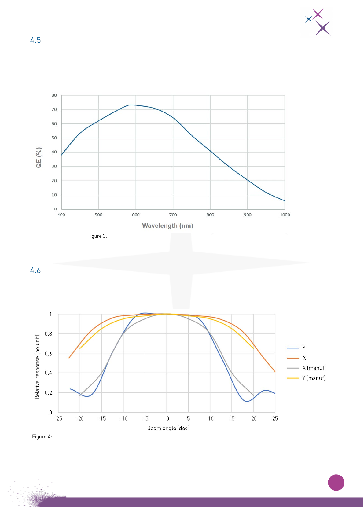
Quantum efficiency curve
The typical spectral response curve of the sensor measured at a sensor temperature of 20°C is shown
below.
The peak quantum efficiency of > 70% is obtained at 580 nm.
Quantum efficiency of the Sony IMX425LLJ-C sensor between 400 and 1000 nm
Angular acceptance
The angular response is an intrinsic property of the sensor, it characterizes the optical efficiency of the
sensor as a function of incidence angle.
Measured angular pixel response for the detector IMX425LLJ-C (normalized) by First Light Imaging and by sensor manufacturer.
15
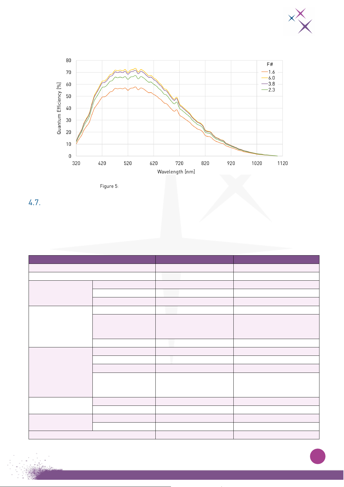
The angular acceptance will affect the quantum efficiency of the detector. The figure
below shows the influence of collecting light within a cone of various F#.
Quantum efficiency as a function of wavelength at various F#
Main camera features
The various features of the C-BLUE One camera will be described in detail in section 10. Below is a
quick overview of the main characteristics.
Table 7 - Main camera features
Feature
IMX425 Performance
IMX426 Performance
A/D convertor
8 or 12 bits
8 or 12 bits
Conversion gain High or Low High or Low
Analog gain
Min
0 dB
0 dB
Max
24 dB
24 dB
Granularity
0.1 dB
0.1 dB
Digital gain
Min
0 dB
0 dB
Max 24 dB
(allowing up to 48 dB total
gain)
24 dB
(allowing
up to 48 dB total
gain)
Granularity
0.1 dB
0.1 dB
Exposure duration
using global shutter
Min 8 bits
6.16 µs
5.8 µs
Min 12 bits
6.64 µs
6.42 µs
Max
1/frame rate
1/frame rate
Maximum exposure
time, at minimum
framerate
10 000 s
(frame rate of 0.0001
frames/s)
10 000 s
(frame rate of 0.0001
frames/s)
Maximum framerate
in full frame
8 bits
662.1 frames/s
1594 frames/s
12 bits
481 frames/s
941 frames/s
Maximum framerate
16 lines in 8 bits
3997 frames/s
7366 frames/s
16 lines in 12 bits
3458 frames/s
5150 frames/s
Region of interest mode
Support of up to 64 ROIs
Support of up to 64 ROIs
16
5. THERMAL MANAGEMENT
Sensor thermal management
The camera is equipped with one stage Peltier thermoelectric module in order to improve dark current
and readout noise performances of the sensor.
Camera thermal management
Overview
The design of the C-BLUE One camera is optimized to dissipate heat by the bottom face.
The camera can be configured to maintain the sensor temperature to a setpoint specified by the user.
This feature is disabled by default.
Optimal camera performances are obtained when the sensor temperature is regulated around 10°C.
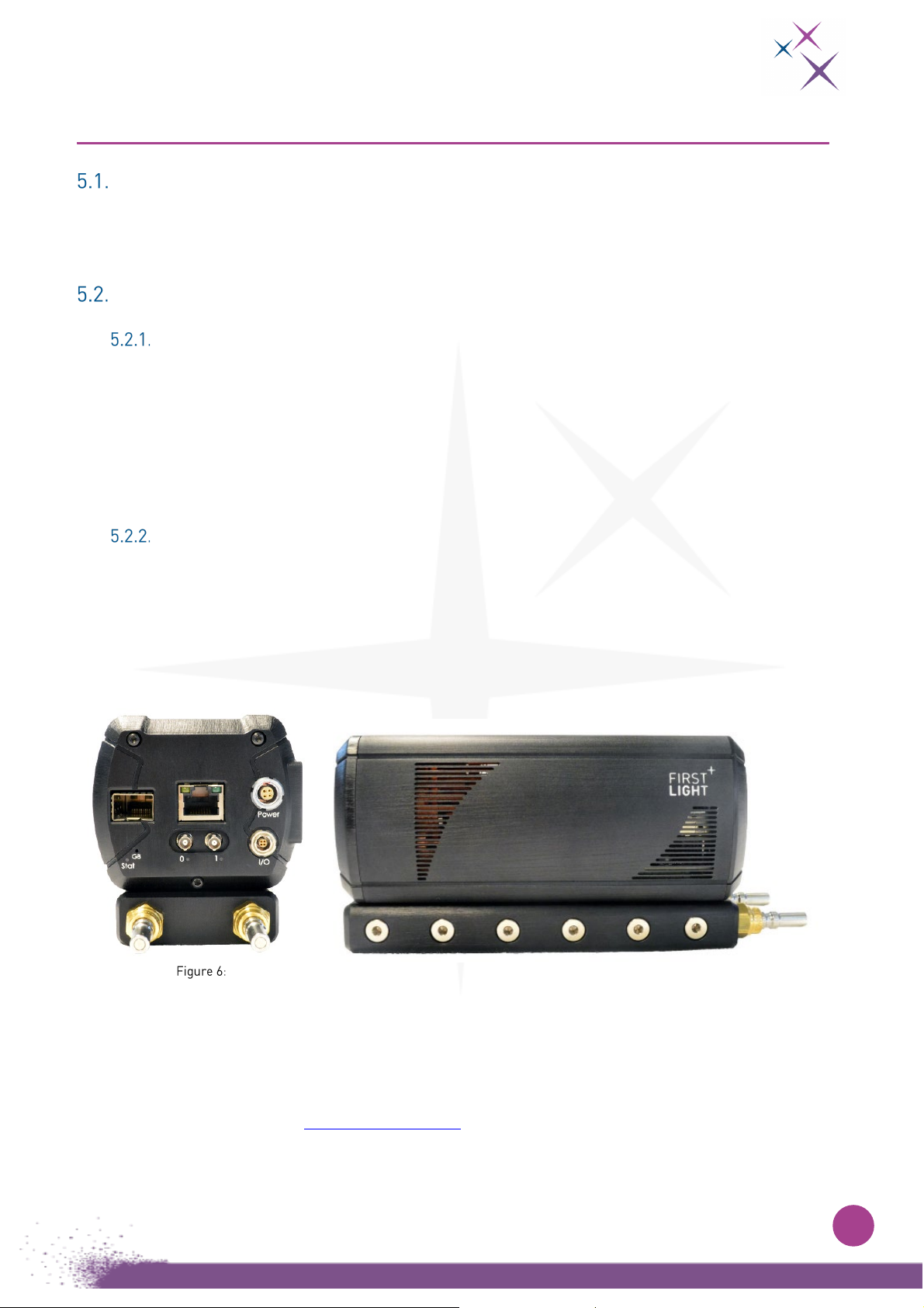
Optional water-cooled plate
To improve thermal performances, C-BLUE One can use an external liquid cooling plate sold
separately. It can be mounted directly on the camera (see Figure 6). Please use thermal paste
(
recommended reference: Fischer elektronik WLPK10
)between the cooling plate and the lower side
of the camera in order to improve thermal cooling efficiency. The cooling plate can be fixed to the
camera with six M3x16mm screws.
Back and side view of C-BLUE One. Configuration with the camera attached to its cooling plate
The cooling plate must be used with a water-cooling system. First Light Imaging recommends using
an active system, but a passive one can also be used. The water-cooling system that can be bought
with C-BLUE One is INR-244-831, 220W (
SMC).
First Light Imaging can supply a full cooling pack including the chiller, hoses and connectors. Please
contact us for more details at contact@first-light.fr.
17
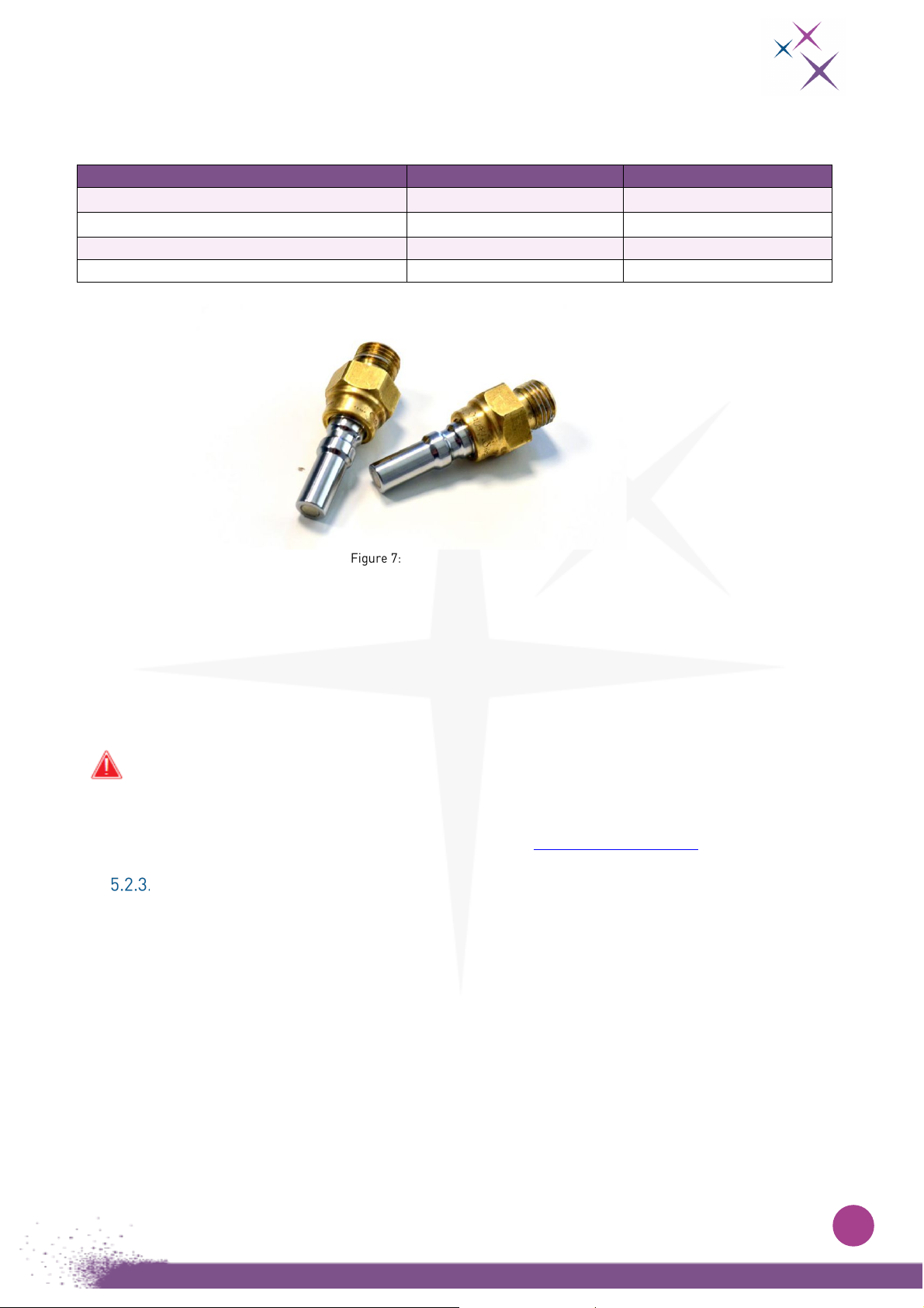
The requirements for the water-cooling system are as follows:
Table 8 – Cooling system recommendations
Parameter
Value
Unit
Recommended cooling fluid temperature 20 °C
Recommended cooling output at 20°C 120 W
Minimum pump flow
> 2
L/min
Maximum pressure
10
bars
Male Staubli CBI03 connectors
Heat is evacuated by circulating a cooling fluid through two rears connectors (G1/8, 10 mm thread).
With the cooling pack, two male connectors (Staubli CBI03) and compatible mating connectors
mounted on flexible houses are provided.
Distilled water or deionized water can be used if liquid temperature is > 5°C. For lower temperatures,
ethylen glycol is advised. Please check the recommendations of your cooling system.
To avoid leaks, make sure that the cooling system is correctly connected before turning on
the chiller. Water will damage the camera.
For more information, please contact First Light Imaging at support@first-light.fr.
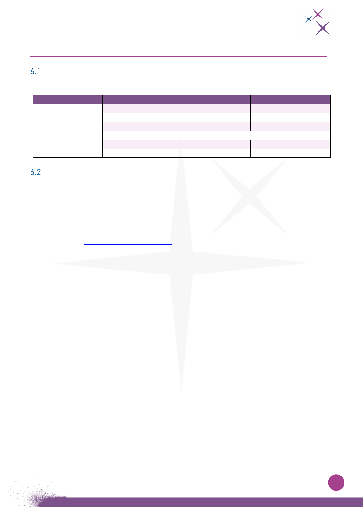
Thermal performances
The table below sums up the performances that can be expected from the camera with the different
thermal management options available.
The achievable sensor temperature range is improved when using LEMO® power connector because
more power is available (60W with LEMO® against 26W for PoCXP).
Due to the limited power available when the camera is powered using PoCXP, the regulation of the
sensor to 10°C may not be possible, depending on the environmental conditions of the camera. In this
case, either increase the sensor temperature setpoint, or use the dedicated external power supply.

18
Table 9 - Thermal management performances and temperature minimum set point
Power supply
Cooling method
Air
temperature
Water
temperature
Sensor
minimum
set point
External power
supply
Air cooling, fan at full speed < 35°C - 10°C
Air cooling, fan at full speed < 45°C - 20°C
Water cooling / no fan <45°C < 45°C 10°C
PoCXP
Water cooling / no fan ≤ 30°C < 40°C 10°C
The temperature maximum set points are:
10°C below the ambient air temperature, in the case of air cooling
10°C below the water temperature, in the case of water cooling
Electronics protection
In case of overheating or too cold temperature depending on external operating conditions, the camera
will automatically shut itself down to protect electronic components.
Please note that it is not possible to switch off this functionality.
The internal firmware monitors at each time the temperatures on different parts and boards. Each
temperature must be within the accepted range.
Before shutting down the camera, the firmware tries to limit the power consumption of the camera to
decrease the heat that is generated.
To recover the use of the camera, after the camera went back in the authorized range of temperature,
the user must reboot the camera by unplugging/plugging the power.
19
6. MECHANICS
Overview
Table 10 – Overview of mechanical parameters of C-BLUE One
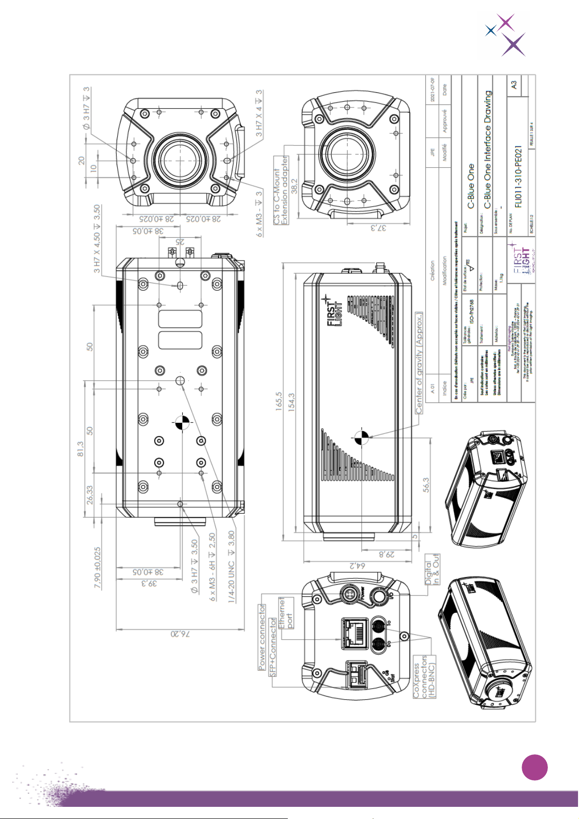
Mechanical drawings
The camera is designed to deliver the best precision possible regarding the optical alignment of the
sensor.
For further information about mechanical tolerances, see drawing below.
The camera’s latest mechanical drawings are available from First Light at: support@first-light.fr, or on
“Your Library” on www.first-light-imaging.com.
Parameter
Values
Units
Dimensions (without
lens adaptor)
Length
154.3
mm
Width
76.2
mm
Height
64.1
mm
Lens mounts
C-mount, CS-mount
Weight
Weight
< 1100
g
Cooling plate
450
g
20
Other manuals for C-BLUE One
1
Table of contents
Other First Light Lighting Equipment manuals


Popular Lighting Equipment manuals by other brands

Procopi
Procopi CALYPSO Installation and operating instructions

LED World
LED World FA36M57-2M-12V-X Important instructions

Eterna
Eterna VECOMEM3 installation instructions

Elation
Elation KL FRESNEL 4 CW user manual

VisionAid
VisionAid StandBright 2 instructions

ProLights
ProLights EclProfile FW IP user manual


