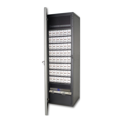
Strand Lighting CD80 User manual

CDSO1.2Kw Pack
.~
Strand Lighting
Price: $20.00
Operator's Reference
Part#: 2-450064-010
Document Revision: CO
By: D. Lammers
Date: 08/29/89

Information contained inthis document is disclosed in confidence and may not be
duplicated in full or in part by any person without prior written approval of Strand
Lighting. It's sole purpose is to provide the user with adequately detailed
documentation so as to efficiently install, operate, maintain, and order spare parts
for the system supplied. The use of this document for all other purposes is
specifically prohibited .
The material in this manual is for information purposes and is subject to change
without notice. Strand Lighting assumes no responsibility for any errors or omis-
sions which may appear in this manual.
Comments and suggestions for corrections and/or updates to this manual are
appreciated and will be considered for the next printing if forwarded in writing
(red-lined photocopy preferred} to the Documentation Manager or Applications
Engineering Manager at the West Coast facility of Strand Lighting North America.
Copyright 1989, Strand Lighting. All rights reserved.
West Coast Office (AllServices):
18111South Santa FeAve.
Aancho Dominguez, CA 90221
East Coast Office (Field Service, Sales):
20 Bushes Lane
Elmwood Park, NJ 07407
Canadian Office (All Services):
6490Viscount Road
Missisauga, Ontario L4V 1H3
Canada
(213) 637-7500
(201) 791-7000
(416) 677-7130

Maintenance
This section provides trouble-shooting and maintenance information for the COBO1.2Kw Pack.
For electronic repair information, see •coao1.2Kw Pack Electronics Repair Procedures•
(Strand part #8-700193-000).
7. Basic Trouble-Shooting ................................................................................... 35
7.1 Component Removal ...................................................................................................35
7.2 System Malfunctions Common to One or More Power Supplies ............................36
7.3 Dimmer Problems Common to a Single Ramp Card ............................................38
7.4 Dimmer Problems Not Related by Phase or a Common Phase ............................39
8. Periodic System Maintenance .......................................................................... 41
Appendices
A. Spare Parts ................................................................................................. 43
References
List of Figures
1. COBO1.2Kw Pack ........................................................................................................15
2. COBO1.2Kw Pack Exploded View .............................................................................16
3. COBO1.2KwPack Wall Mounting .............................................................................20
4. XLRTo mini-SwitchCraft Adapter .............................................................................21
5. 1.2Kw Pack Power Connection ...................................................................................25
6. Multiplexed 1.2KwPack Control Hookup ..................................................................26
7. COBO1.2KwPack (Hardwired Control) Installation ..................................................27
8. Analog 1.2Kw Pack Hookup to Strand Analog Console .......................................28
9. Analog 1.2Kw Pack Hookup to Non-Strand Analog Console .................................29
1O. Analog 1.2Kw Pack Hookup to Strand Multiplexed Console ..................................30
11. Reference Adjustment Locations .............................................................................31
12. COBODimmer Output Curves ...................................................................................32
Index ........................................................................................................................47
iii

Table of Contents
CD80 1.2Kw Pack Operator's Reference
Introduction
This section provides information on manual organization. It also details procedures for getting
your suggestions to Strand Lighting, and receiving help if necessary.
1. About this Manual ..............................................................................................3
1.1 Manual Organization .....................................................................................................3
2. TechnicalAssistance ..........................................................................................5
2.1 In Case of Problems .....................................................................................................5
2.2 Technical Questions .....................................................................................................5
2.3 Parts Purchases ...........................................................................................................5
2.4 Comments and Suggestions ..........................................................................................5
System Information
This section provides specifications and basic layout information for the COBO1.2KwPack.
3. Dimmer Pack Description .................................................................................9
3.1 General ...........................................................................................................................9
3.2 Environmental ................................................................................................................9
3.3 Servicing ...........................................................................................................................9
3.4 A.C. Power .....................................................................................................................9
3.5 Control Signal ..............................................................................................................
1D
3.6 Dimming Characteristics ..............................................................................................1D
3.7 Dimmer Output ........................................................................................................10
3.8 Protection ...................................................................................................................1D

4. Basic Co,nponint Layout ..............................................................................11
4.1 Chassis .........................................................................................................................11
4.2 Control Electronics (Multiplexed Analog Input) .......................................................12
4.3 Control Module (Discreet Analog Input) ..................................................................13
4.4 Power Control and Cooling Assemblies ..................................................................13
Operation
This section provides information on installation and operation of COBO1.2KwPacks.
5. Installation ......................................................................................................19
5.1 Install Packs - Portable COBO1.2Kw Pack ..................................................................19
5.2 Install Packs - Wall Mounted COBO1.2Kw Pack .......................................................20
5.3 Connect Control Signal .............................................................................................21
5.4 Set Thumbwheel Switches ........................................................................................22
5.5 Systems with Multiple Control Cables ........................................................................22
5.6 Mixing COBOPacks ...................................................................................................23
5.7 Analog Control Module Hookup .............................................................................23
5.8 Set Phase Changer ...................................................................................................24
5.9 Connect Power ........................................................................................................24
5.1
o Fault Protection ........................................................................................................24
5.11 Test Controller ..............................................................................................................24
6. Di,nmer Pack Calibration ..............................................................................31
6.1 Ramp Card Calibration ..............................................................................................31
6.2 Power Supply Card Calibration ...................................................................................31
ii

Introduction
CD80 1.2Kw Pack Operator's Reference
This section provides information on manual organization. It also details procedures for
getting your suggestions to Strand Lighting, and receiving help if necessary.

1. About this Manual
This manual provides information on the operating and maintenance procedures
for CD80 1.2Kw Packs. Circuit descriptions are included in the CD80 1.2Kw
Pack Repair Procedures Manual for those who wish to do their own circuit level
maintenance of this equipment.
1.1 Manual Organization
This manual contains 5 major sections as shown below.
INTRODUCTION
Manual organization (chapter 1)
How to get help (chapter 2)
SYSTEM INFORMATION
Specifications (chapter 3)
Basic Description (chapter 4)
OPERATION
Installation (chapter 5)
Calibration (chapter 6)
MAINTENANCE
CD80 1.2Kw Pack trouble-shooting (chapter 7)
Periodic maintenance procedures (chapter 8)
APPENDICES
Appendix A
3

2. TechnicalAssistance
COBO1.2Kw Packs are designed to require a minimum of maintenance and ser-
vicing. Circuit descriptions are included in the COBO
1.2Kw Pack Repair Proce-
dures Manual for those who wish to to do all of their their own repair and main-
tenance work. Other documentation may be purchased through Strand Lighting
Customer Service.
2.1 In Caseof Problems
Ifequipment fails to operate properly upon installation, or under normal load and
temperature conditions, and basic trouble-shooting procedures are not effective,
please contact Strand Lighting Field Service at the office serving your area.
Strand Lighting will issue an RGA (Return Goods Authorization) before the return
of any defective materials. This allows tracking of returned equipment, and
speeds its return to you.
2.2 Technical Questions
For technical questions regarding setup, operation, or maintenance of this
equipment, please contact the Strand Lighting Field Service office serving your
area (see reverse side of manual title sheet for addresses and phone numbers).
2.3 Parts Purchases
For purchase of spare parts or documentation, Please contact Strand Lighting
Customer Service in the Rancho Dominguez office.
2.4 Comments and Suggestions
For comments regarding equipment functions and/or suggested enhancements,
please call or write to the Control and Dimming Product Manager at the Rancho
Dominguez office.
For comments on this manual, please write to the Technical Publications
Manager at the Rancho Dominguez office.
5

System Information
CDBOJ.2KwPack Operator's Reference
This section provides specifications and basic layout information for COBO1.2Kw Packs.
7

3. Dimmer Pack Description
The COBO1.2Kw Pack is a lightweight portable performance dimming pack con-
taining 24 1.2Kw dimmers .
3.1 General
Size - 23.25" x 20.00' x 7.75'
Weight - 65 pounds
.125' (3mm) aluminum alloy housing.
Baked enamel finish, black semi-gloss, with off-white silkscreened
graphics .
Integral carrying handles for transporting.
Optional wall mounting .
3.2 Environmental
Operating Temperature - 40 degree maximum ambient.
Low noise fan for efficient cooling.
3.3 Servicing
Rapidly replaceable electronics.
Rapidly replaceable SSA modules.
3.4 A.C. Power
100-140VAC, 50/60Hz.
Three phase power requirements:
1.2Kw Pack - 120V/208 VAC, 80 Amps, 4-wire plus ground.
Single phase power requirements:
2.4Kw - 120V/240 VAC,120 Amps, 3-wire plus ground.
Internally field changeable between three phase and single phase
power input configurations.
9

3.5 Control Signal
Compatible with USITTAMX 192 control signals.
Input Control Voltage - Multiplexed Oto 5.0V DC level
Input Control Current - Less than 1 ma
Signal Input Impedance - Lineterminated by 1.8Kin series with .001 uF
Optional 0-10VDC input electronics module (switchable between
AMX192 and analog).
3.6 Dimming Characteristics
Input vs. output - IESsquare law characteristics.
Output Response Time - Better than 0.1 seconds
Line Regulation - +2% with changes in line from 1oavto 132 VAC.
Load Regulation - Better than +2% with changes in load from 10 watts
to full load any point in the dimming curve.
3.7 Dimmer Output
Output Waveform -Variable conduction angle 120VAC Sine Wave.
RiseTime - Greater than 320 micro-seconds.
Efficiency - Betterthan 95% at full load.
Load Range - 1owto 1.2Kw.
Output Capacity -Twenty four 1.2Kwchannels.
Available with Grounded Twist Lock, Pin Plug, U-Ground, or terminal
strip outputs.
3.8 Protection
10
Overvoltage Protection - fuses on Motherboard and Power Supply.
Front panel overtemperature and power indication.
Solid State Relay Peak Surge Rating: - 600 AMPS.
Short Circuit Protection - fully magnetic circuit breakers.

4.
4.1
Basic Component Layout
Chassis
The COBO1.2Kw Pack chassis consists of a main structural chassis (bottom
housing and front panel), a removable top, and an interchangeable rear connec-
tor panel. The heavy gauge structural panels create a rugged container even
though assembled with only four pieces.
The main structural chassis consists of the bottom housing and front panel fas-
tened rigidly together. The front panel is recessed to protect the circuit breakers
and panel components.
The front panel, constructed of .090 thick aluminum alloy, contains cutouts for
the U.L. listed circuit breakers and a removable panel which hides the plug-in
printed circuit boards.
The bottom housing, constructed of .125 thick aluminum alloy, supports a heat
sink subassembly (mounting the solid state relays and an overheat thermostat),
a fan, a fan guard, a circuit breaker/torroidal choke subassembly (with chokes
solidly mounted in a 'clamshell" Lexan retaining channel), and a power-in
knock-out, for input power wiring wiring. The rear panel is attached to the bot-
tom housing and recessed to protect the connectors. Four large diameter feet,
approximately 3/4' high, are attached to the underside of the bottom housing
and existing feet mount holes are accessible for easy wall mounting.
The rear connector panel, constructed of .090 thick aluminum alloy, is manufac-
tured in four customer options:
1) Pin connectors
2) Twist lock GTL connectors
3) Straight blade (Duplex) connectors
4) A terminal block for hard wiring of outputs plus control
The top cover, constructed of .125 aluminum alloy, fastens to the main chassis
by four screws, and allows easy access for servicing. Recessed handles are in-
tegrated into the top housing for easy one man carry capability. Instruction
labels are affixed to the underside of the top cover and a warning label...,
'Disconnect power before removing top~...attached to the top of the cover.

4.2 Control Electronics (Multiplexed Analog Input)
12
The control electronics for the 1.2KwPack consists of a Motherboard, four COBO
Rack Ramp Cards, one COBO Rack Power Supply Card, and a Control Panel
assembly which is screwed on in front of the other control components, and
hides them.
A. Motherboard
The Motherboard serves to connect the control components together. It
also contains the phase references for phases B and C, and a clock cir-
cuit which allows testing the pack by bringing all dimmers in the pack to
FULL
B. Ramp Card
Ramp Cards provide control signal demultiplexing and analog to pulse
width conversion.
Up to 192 dimmer levels are time multiplexed on the ANA (analog) line of
the control cable (control terminal 4). Levels vary from 0-SVDC, repre-
senting dimmer output levels of 0-100%. A differential clock on the CLK-
(minus clock) and CLK+ (plus clock) lines (control terminals 1 and 3)
synchronizes the dimmer rack with the control console. The multiplex-
ing scheme conforms to the USITT AMX192 Dimmer Signal Specifica-
tion. 6W and 12W dimmers require 2 clock cycles or dimmer posi-
tions.
Each Ramp Card contains the following circuitry:
1) clock receiver and reset detector
2) counter/decoder circuit
3) analog buffer
4) analog demultiplexer
5) A.C. zero crossover detector
6) square law curve generator
7) output solid state relay driver
8) power supply
C. Power Supply Card
The Power Supply Card conditions AC power from power phase A, and
supplies the AC line reference source for the phase A Ramp Card.
The Power Supply Card also has an SSA for fan power, which is ener-
gized from the Ramp Card when system clock signals are present. A
fuse on the Power Supply Card provides overload and short circuit
protection for this SSA.

D. Control Panel
The contains input plugs for the AMX192 signal, the thumbwheel switch
for pack number selection, a slider controller for testing the dimmers, a
'NORMAL/TEST' switch to activate the slider control, and 'POWER' and
'OVERTEMP' indicators.
4.3 Control Module (DiscreetAnalog Input)
A discreet analog input version of the pack is available. This pack contains an
analog to multiplex converter in addition to the other control circuitry.
This converter plugs into the Motherboard, and requires a different removable
control panel from the 'Multiplex Only' version. The 'Multiplex/Analog• version of
the control panel allows selection of AMX192 or analog signals from a front
panel switch.
4.4 Power Controland CoolingAssemblies
The following circuit and thermal elements in the bottom housing serve to con-
trol and dissipate power in the CD80 1.2Kw Pack:
A. 12 SSAs (1 for each 2 dimmers), rated appropriately for the dimmer
power rating, and mounted on a common 18' long heat sink anchored
to the bottom housing. Each dual SSA is field replaceable.
B. One torroidal choke for each dimmer is mounted in a common assembly
adjacent to the heat sink.
C. One primary, fully magnetic circuit breaker for each dimmer is mounted
infront of the torroidal chokes.
D. A fan mounted on the positive pressure side of the heat sink provides
approximately 70 CFM (derated) of cooling airthrough the enclosure.
E. A phase changing/terminal block assembly on the bottom housing
provides termination of either 3 phase 4-wire plus ground 120/208 VAC
80AMPS,or single phase 3-wire plug ground 120/240 VAC 120AMPS.
13

1______ 20.37
15A Primary Circuit Breakers (24)
(Fully magnetic)
AMX192 Control Input
AMX192 Control Output
Power Light
Air Outlet Vent
Dimmer Pack Select
est Controller
nalog Input (ANA/MPX units only)
TEST/NORMAL Switch
MPX/ANA Switch (MPX/ANA uinits only)
Cover for access with 4 flat head screws
(See exploded view for options)
Figure 1. CD80 1.2Kw Pack
Knockout for
Power Cord
Air Inlet
an Guard
15

Rear Panel Assembly
1 3 Pole 20A Pin Conn. (3-283359-01-0)
2 3 Pole 15A GTL Conn. i3-283369-01 b)
2 3 Pole 20A GTL Conn. 3-283355-010)
3 3 Pole 20A U-Ground -283356-010
4 Teminal - Hard Wired 3-283357 -01o
Removable
Control Panel
(Multiplex - 3-283358-010)
(Analog/MPX - 3-283360-010)
1.2Kw Choke/Breaker Ass'y
(3-169006-010)
Fan w/Fan Guard
(4" dia., 100CFM)
(1-260014-000)
Main Chassis Assem
(2-190137-010) I
Power Input
Terminal Block -----
Cover Ass'y (3-151004-010)
-----
-----
-------J
Figure 2. CD80 1.2Kw Pack Exploded View
16
I
Card Cage
(3-254004-010)
I
I
I
Control PCBs

Operation CDBOJ.2Kw Pack Operator's Reference
This section provides information on installation and operation of COBO1.2Kw Packs.
17

5. Installation
The location of wiring runs may affect dimmer performance and should be
planned before laying out the control and dimming equipment.
DO NOT run power feed or load wires in the same cable
bundle, conduit or wireway as control wiring. Where control and
power wiring must cross, they should cross at as close to a right angle
as possible.
DO NOT run wiring from other manufacturers' equipment in
the same cable bundle, conduit, or wireway with CDS0 1.2Kw
Pack wiring.
DO NOT run wiring from unrelated Strand Lighting or Strand
Electro Controls equipment in the same cable bundle, conduit,
or wireway with CD80 1.2Kw Pack wiring.
DO NOT run wiring in ways other than shown on system riser
diagram in permanent installations.
DO NOT substitute plastic conduit for metal where conduit is
called for in permanent installation. Metal conduit acts as a ground and
shield.
Since this is portable equipment, and installed under many circumstances, fol-
lowing all of the above constraints in all installations may not be possible.
However, following these constraints where possible will help insure consistent
and stable system operation.
5.1 Install Packs -Portable CD80 J.2Kw Pack
The CD80 1.2Kw Pack may be placed on any flat surface for normal operation.
Up to 8 units may be stacked vertically if required. No more than 2 units should
be placed side to side unless at least 24 inches is provided between packs.
Otherwise, the hot air exhaust from each unit will simply feed into the next. In
permanent or semi-permanent installations, build shelves to hold two packs
separated by at least 24 inches horizontally. Vertical shelf spacing should allow
removal of the CDBO1.2Kw Pack top covers for access to SSR modules if re-
quired.
19

5.2 Install Packs- WallMounted CDBO1.2Kw Pack
20
The wall mounted COBO1.2Kw Pack (Terminal Strip 1.2Kw Pack) provides load
and control terminal strips on the rear panel of the pack, and provides a termina-
tion for remote overtemp indication.
A. Set mounting hardware in wall according to the figure.
B. Removetop of pack and mount on wall. Make certain that the fan is at
the bottom of the unit as mounted.
C. Attach conduit as indicated for power, load, and control wires, and pull
wiring. Bring wires into pack as shown. This configuration is designed
for minimum crosstalk between the AC line and the control wiring.
Keep Clear
-Ami:~~•~,.. I
20.5' (52.1cm)~
1-16' (40.6cm)---t--j I Knockout For
Control Wires
LEFT
SIDE
nockout For \ /
T* ~-1
;- Control
-++,[}
Power Wirr Mounting Holes
23.5' 20.25'
(59.7cm)+
~~II~~
Jj-lom)
TOP (COVER REMOVED)
l-=10--:--I-Air Intake Area
I (25.4cm) I Keep Clear
T c::J
RIGHT
SIDE
8.5'
(29.85cm) Knockout For
Power Wires
l_ '--,I'--='-----=--'
Air Inlet Fan
Figure 3. CD80 1.2Kw Pack Wall Mounting
Panel
Primary
Circuit
Breakers

5.3 Connect ControlSignal
COBODimmer Racks accept control signals conforming to the USITT AMX192
Dimmer Signal Specification.
Short extensions of the multiplex signal, where TA4{fY4 connectors are used,
are made with Belden cable #8723 (2 pairs of shielded 24 gauge wire). All other
runs (in or out of conduit) are made with Belden #9156 (2 pairs of unshielded 18
gauge wire). Maximum allowable distance from control console to last dimmer
cabinet is 1000feet.
The three types of connections provided in Strand Lighting equipment for the
AMX192signal are the XLR style connector, the TA4{fY4 Series Mini-SwitchCraft
connector, and terminal blocks. COBO1.2Kw Packs use XLR connectors for
control signal connection. Pin assignments are shown below.
COBO
XLR TA4{TY4 Term. Block
Function Pin# Pin# Pin#
-CLOCK 4 1 1
+ CLOCK 2 3 3
COMMON 1 2 2
ANALOG 3 4 4
Interconnection between equipment with different plug types requires an
adapter cable. The plugs on this adapter are not connected pin to pin.
See figure below for proper adapter wiring.
"XLR" Style
Connector
4 -CLK -Clock
TA4/TY4 Series
Connector
~
Multi lexedAnalo
COM Common
+CLK +Clock
Figure 4. XLR To mini-SwitchCraft Adapter
21
Table of contents
Other Strand Lighting Lighting Equipment manuals
Strand Lighting
Strand Lighting Circular Saw User manual
Strand Lighting
Strand Lighting Contact Power Pack Original operating instructions

Strand Lighting
Strand Lighting ClassicPalette User manual

Strand Lighting
Strand Lighting MX User manual

Strand Lighting
Strand Lighting MX Service manual

Strand Lighting
Strand Lighting EC21 User manual

Strand Lighting
Strand Lighting Wallrack User manual
Strand Lighting
Strand Lighting 100 User manual