First Light C-RED 3 User manual
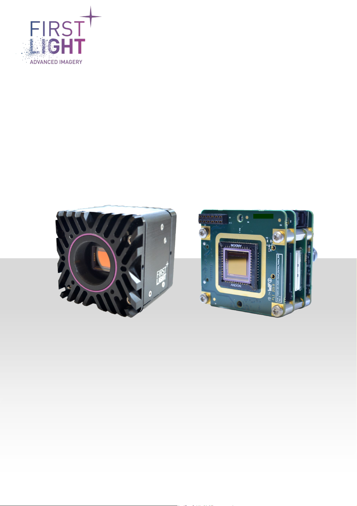
C-RED 3 & C-RED 3 Module
User Manual
C-RED 3 User Manual_20211021

2
TABLE
1. INTRODUCTION ............................................................................................................................. 6
Caution.............................................................................................................................. 6
Overview............................................................................................................................ 6
Symbols and Indications...................................................................................................7
Disposal - DEEE................................................................................................................7
2. WARNINGS................................................................................................................................. 8
General warnings..............................................................................................................8
Never open your camera ..................................................................................................8
Power circuitry..................................................................................................................8
3. TECHNICAL SPECIFICATIONS AND OPERATIONAL ENVIRONMENT........................................ 9
4. TYPICAL PERFORMANCES*....................................................................................................... 9
5. CONTENTS OF PACKAGE..........................................................................................................10
Package content ............................................................................................................. 10
Camera serial number ................................................................................................... 11
Resources....................................................................................................................... 11
Test report............................................................................................................... 11
Additional resources ............................................................................................... 11
6. DESCRIPTION AND TECHNICAL SPECIFICATIONS..................................................................12
SWIR CMOS sensor......................................................................................................... 12
SNAKE-SW TECLESS introduction.......................................................................... 12
Spectral response ................................................................................................... 12
C-RED 3 camera ............................................................................................................. 13
Mechanical and optical interfaces........................................................................... 13
Description and minimum specification accessories..................................................... 15
Power input ............................................................................................................. 15
Thermal management............................................................................................. 15
Cooling system ........................................................................................................ 15
Communication interface........................................................................................ 15
Camera Link.............................................................................................................. 16
Micro USB 3.0 Type B................................................................................................ 16
7. SETTING UP AND START UP CAMERA .....................................................................................17
Connecting your camera................................................................................................. 17

3
Power FISCHER CONNECTORS cable connection ...................................... 17
Camera Link®connection (for C-RED 3 CL only) .................................................... 17
USB connection (for C-RED 3 USB only) ................................................................. 18
FliVision Graphical User Interface.................................................................................. 19
Powering up/down.......................................................................................................... 19
Power ON: ............................................................................................................... 19
Power OFF:.............................................................................................................. 19
Camera status ................................................................................................................ 20
8. READOUT MODES .....................................................................................................................21
Integration/readout function .......................................................................................... 21
Integrate while read (IWR)....................................................................................... 21
Integrate then read (ITR)......................................................................................... 22
ITR / IWR consideration........................................................................................... 22
Readout mode................................................................................................................. 23
Single Read.............................................................................................................. 23
High Dynamic Range mode ..................................................................................... 23
AGC .......................................................................................................................... 24
Data acquisition mode .................................................................................................... 25
Detector geometry................................................................................................... 25
Pixel format (ADU)................................................................................................... 26
Full frame mode...................................................................................................... 26
Cropping mode ........................................................................................................ 27
Conversion gain .............................................................................................................. 29
9. OPERATION...............................................................................................................................30
Data format..................................................................................................................... 30
Camera Link®(for C-RED 3 CL only)....................................................................... 30
Camera Link®frame grabber.................................................................................. 30
USB (for C-RED 3 USB only).................................................................................... 31
Internal synchronization................................................................................................. 32
External synchronization ................................................................................................ 33
Cable assembly ....................................................................................................... 34
FPS_Tint_in timing diagrams.................................................................................. 36
Standard polarity / externally controlled integration time....................................... 36
Inverted polarity / externally controlled integration time ........................................ 36
Standard polarity / internally controlled integration time........................................ 37

4
Inverted polarity / externally controlled integration time ................... 37
Latency .................................................................................................................... 38
Triggered acquisition...................................................................................................... 38
Trigger selection ..................................................................................................... 39
Software trigger ...................................................................................................... 39
External trigger ....................................................................................................... 39
Bad Pixel Correction....................................................................................................... 42
Bad Pixel map edition.............................................................................................. 43
Bias/Flat Correction ....................................................................................................... 44
Legacy bias/flat computation .................................................................................. 44
bias/flat computation .............................................................................................. 44
Adaptive Bias ........................................................................................................... 45
HDR Bias/Flat correction additional information ................................................... 46
Bias correction file format ...................................................................................... 47
Flat correction file format ....................................................................................... 47
Pixel value offset............................................................................................................. 47
Dark optimization ........................................................................................................... 47
Tag generation................................................................................................................ 48
Frame marker configuration................................................................................... 48
Thermal protection......................................................................................................... 49
Camera presets .............................................................................................................. 49
Camera optional features............................................................................................... 49
Camera advanced settings ............................................................................................. 50
Dark level adjustment ............................................................................................. 50
Integration time granularity .................................................................................... 50
Anti-blooming.......................................................................................................... 51
Camera tuning......................................................................................................... 51
Camera capabilities ........................................................................................................ 51
Embedded HTTP server.................................................................................................. 52
Ethernet grabber ............................................................................................................ 53
Date/Time management................................................................................................. 53
Image pattern ................................................................................................................. 53
10. DESCRIPTION OF VARIOUS FONCTIONS..................................................................................54
List of available commands............................................................................................ 54
Commands format detail................................................................................................ 63

5
SSH configuration............................................................................................... 63
11. PRECAUTIONS AND MAINTENANCE........................................................................................64
Precaution of use............................................................................................................ 64
Static / electric shocks:........................................................................................... 64
Maintenance ................................................................................................................... 64
Never open the camera........................................................................................... 64
Cleaning of window. ................................................................................................ 64
Storage. ................................................................................................................... 64
Ethernet connection ................................................................................................ 65
12. C-RED 3 MODULE .....................................................................................................................66
Mechanical and optical interfaces.................................................................................. 66
Camera integration......................................................................................................... 68
Specific precaution of use .............................................................................................. 69
13. Optional C-RED 3 Cooling Plate................................................................................................70
Cooling Plate Mounting .................................................................................................. 70
Sensor temperature with the cooling plate.................................................................... 72
14. WARRANTY AND LIABILITY.......................................................................................................74
For the USA..................................................................................................................... 74
Limited Warranty..................................................................................................... 74
Conditions................................................................................................................ 74
Warranty Enforcement............................................................................................ 74
Returns.................................................................................................................... 75
Liability Upon Delivery .............................................................................................. 75
Products Offered “As Is”........................................................................................... 75
No Other Warranties................................................................................................. 75
Limitation of Liability................................................................................................. 75
Purchaser Warranties............................................................................................. 75
Purchaser Indemnification...................................................................................... 75
For the rest of the World ................................................................................................ 76
FLI’s legal guarantee and limit to the guarantee.................................................... 76
FLI’s liability ............................................................................................................ 76
Liability in connection with defective products ....................................................... 76
15. CONTACT US .............................................................................................................................77
For the USA..................................................................................................................... 77
For the rest of the world................................................................................................. 77

6
1. INTRODUCTION
Thank you for choosing C-RED 3!
C-RED 3 features and performances are described in detail within this User Manual.
It contains all information and advice needed to get the optimum performance from C-RED 3.
The module version is a C-RED 3 camera without its mechanical shell, hence this manual is also
relevant for the module version.
The “chapter 12 C-RED 3 MODULE” provides the specific mechanical interfaces and the few additional
information needed for the module version.
You can also find an up-to-date version of this User Manual on our website: https://www.first-light-
imaging.com/user-manuals/
Please contact our support for any question at: support@first-light.fr
Caution
Your C-RED 3 camera contains fragile components.
This User Manual describes precisely how to handle your material properly and to avoid accidents.
Please follow the instructions of use to take advantage of all C-RED 3 performances.
Please carefully read the warnings (section 2) and follow the safety precautions to avoid any personal
injury or damage when using the camera.
Overview
C-RED 3 is a revolutionary ultra-high-speed low noise camera designed for high resolution short wave
infrared imaging.
It is equipped with an Indium Gallium Arsenide (InGaAs) (640 x 512) pixels sensor of 15 µm each.
Thanks to its advanced technology in electronics, software, and its innovative mechanics, C-RED 3 is
capable of unprecedented performances: up to 600 images per second at full frame. C-RED 3 offers
Camera Link® or USB3 interface depending on your camera configuration.
Your C-RED 3 camera contains fragile components, especially the detector. Please always handle your
camera with care.
Note: The truly useful area is 638 x 510. Indeed, the contour of the detector may behave differently.
Always follow the instructions of use.

7
Symbols and Indications
Please read this User Manual and the following definitions carefully to understand the potential
dangers and the precautions to take.
Please refer to this User Manual if a WARNING symbol is marked on the camera.
The CE marking indicates the conformity of the camera to the European
legislation
This pictogram indicates a direct current operation
This pictogram invites the user to refer to the instructions / user manual
This pictogram refers to indoor use
This pictogram refers to Protection class category 1
This pictogram indicates that the product is compliant with the RoHS limitation
Disposal - DEEE
C-RED 3’s sensor contains specific material such as:
- InAs CAS n° 1303-11-3 / EC n° 215-115-3
- GaAs CAS n° 1303-00-0 / EC n° 215-114-8.
In case of disposal, do not throw your camera in waste disposal and send it
back to First Light Imaging

8
2. WARNINGS
General warnings
The equipment must be plugged on an electrical wiring compliant with the relevant standards in the
country (in France: NFC 15-100). This wiring must be protected from overcurrent, overvoltage and
ground defaults.
Connected equipment’s must be compliant with the EN 60950-1 Ed.2006 standard, or to their own
standards.
The power cable plug serves as a disconnection device and should be easily accessible.
Do not place the equipment close to a heating source or a humidity source.
The security of the system which integrates the equipment is the responsibility of the system assembler
only.
For your safety, the equipment must be TURNED OFF AND UNPLUGGED before any technical
intervention.
The security provided with this equipment is only guaranteed with a use in accordance with the specified
purpose. Only use the provided (MEAN WELL USA Inc, model GST18A12-P1J) power supply.
Never open your camera
Do not ever attempt to open your camera. There are indicators inside the camera, if you try to open it
your warranty will be void.
Do not open the camera, your warranty will be void.
Power circuitry
Use the camera with the voltage indicated. Using a different voltage may damage your camera and lead
to fire or electric shock.
Always use the supplied power unit.
9
3. TECHNICAL SPECIFICATIONS AND
OPERATIONAL ENVIRONMENT
* Isolated. With additional external heatsink the temperature can be higher.
4. TYPICAL PERFORMANCES*
*
Typical performances are average values observed
.
Parameters
Values
Power supply
Voltage
100-240 Vac
Frequency 50/60 Hz
Camera’s dimensions
Length
60 mm
Width
55 mm
Height
55 mm
Operation conditions
(Non-condensing
condition)
Maximum temperature
35°C *
Minimum temperature
-40°C
Humidity
95%
Storage conditions
Maximum temperature
60°C
Minimum temperature
-40°C
Parameters
Values
Readout Noise High Gain at 600 FPS Full Frame Tint=50μs Tsensor=40°C
< 40 e-
Full well capacity High Gain
33 ke-
Full well capacity Medium Gain
120 ke-
Full well capacity Low Gain
1400 ke-
10
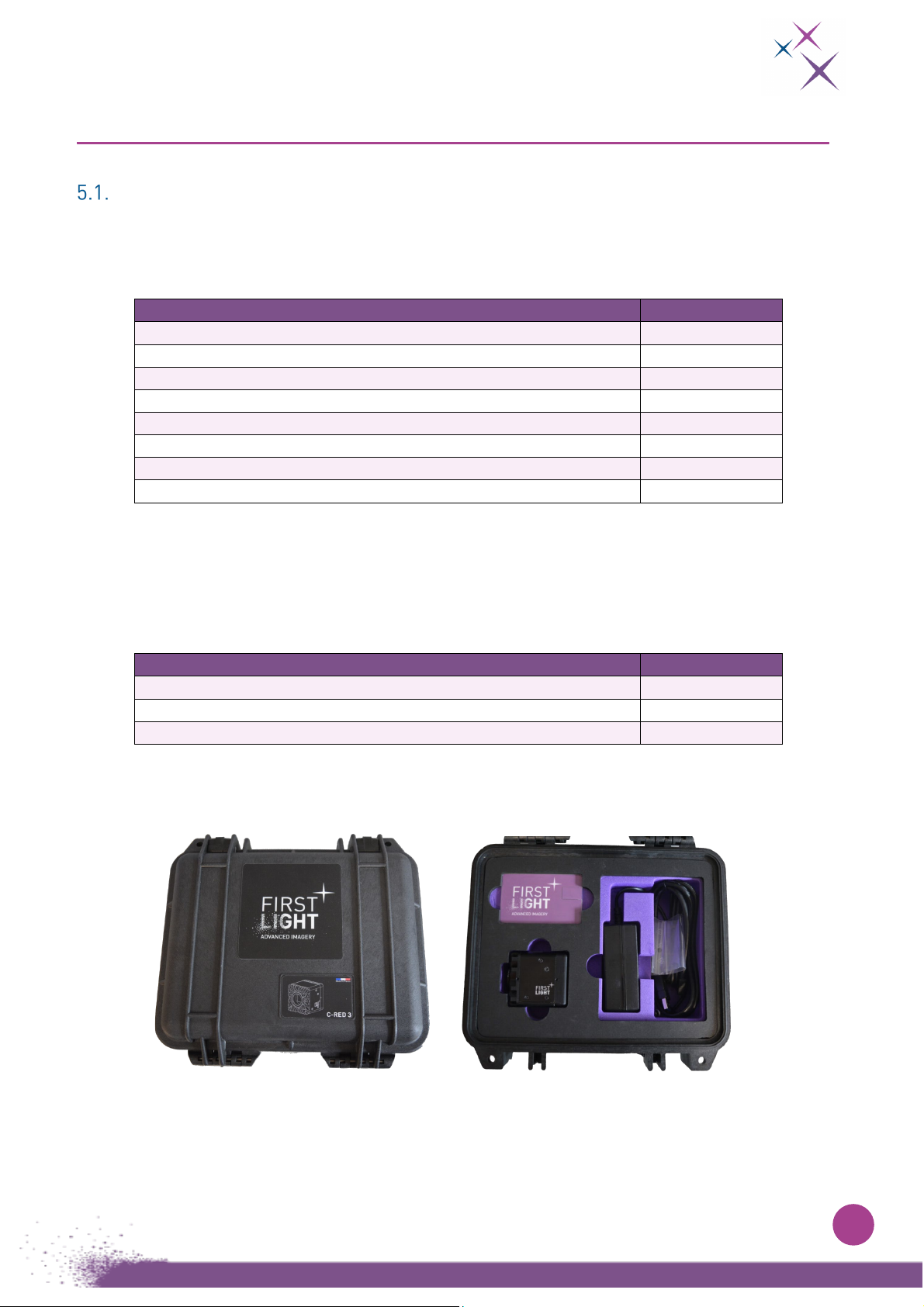
5. CONTENTS OF PACKAGE
Package content
Your C-RED 3 camera will be delivered in a hard Pelicase, with the following components:
Table 1 – Package items* description
Accessories can be ordered separately. Please contact your sales representatives for details and
pricing of the items and accessory packs.
Table 2 - Optional items (can be bought separately)
Figure 1:
On the left, closed Pelicase®. On the right, opened Pelicase® with dedicated spaces*
* Items may differ from pictures.
Items
Number
Camera
1
Power supply
1
Power supply cable (IEC / NEMA / other)
1
USB cable (if USB interface)
1
C-Mount adapter 1
Press button tool (cf. rescue software)
1
Quick Start Manual
1
USB key (User manual, software and camera test report)
1
Items
Number
Cooling plate
1
Cooling unit
1
Personal computer
1
11
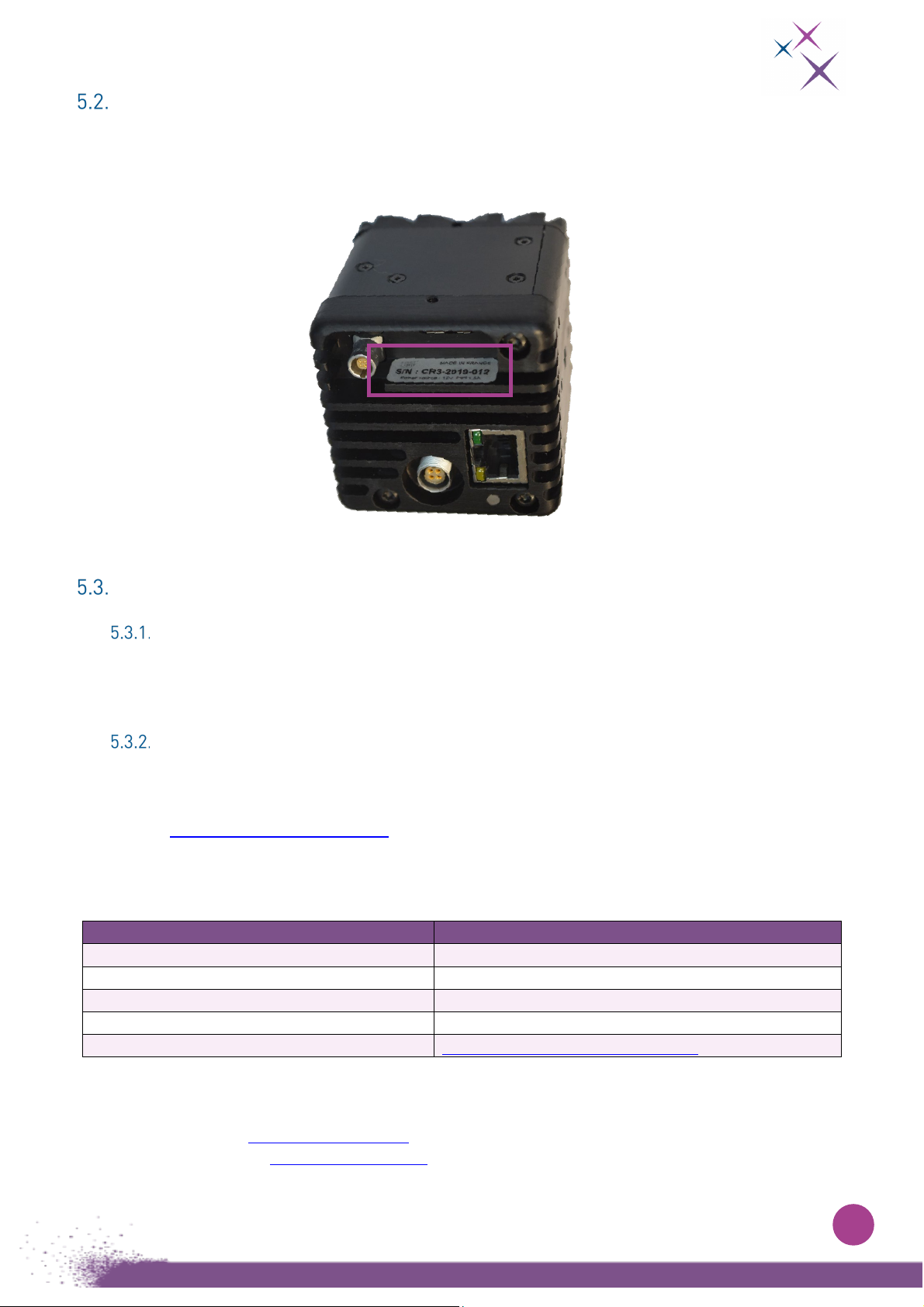
Camera serial number
The camera serial number is available at the rear of the camera. For any support request please
indicate the serial number of your camera.
Figure 2:
SN number at the rear of the camera
Resources
Test report
The performances of your camera have been evaluated by First Light Imaging to ensure the compliance
with our standards. The Test Report is available in the USB key delivered with the camera.
Additional resources
Additional resources, such as technical notes, user manuals, latest software releases, white papers,
etc. are available online. As a customer of First Light Imaging, you can create a personal account on
the website www.first-light-imaging.com and have access to “Your library”, as specific directory with
all the documents concerning your camera.
Table 3 – List of additional resources
If you have inquiries, do not hesitate to contact us.
For technical support: support@first-light.fr
For commercial support: contact@first-light.fr
Items
URL
Download latest software release
Your library
Download latest firmware upgrade
Your library
3D CAD files
Your library
Technical papers
Your library
C-RED 3 product page on the website
C-RED 3 (first-light-imaging.com)

12
6. DESCRIPTION AND TECHNICAL SPECIFICATIONS
SWIR CMOS sensor
SNAKE-SW TECLESS introduction
Designed and fabricated by SOFRADIR, the SNAKE-SW TECLESS sensor is dedicated for flux imaging
applications in the SWIR band. On the one hand, it is responding to night vision, airborne tracking,
surveillance needs, and on the other hand, on various medical applications in preclinical and clinical
such as real-time intra/per/postoperative, oncology, dentistry and neurosciences, for example.
SNAKE-SW TECLESS includes a focal plane array (FPA) composed of a (640 x 512) pixels pitch of 15 µm
each. It is made of photovoltaic (PV) Indium Gallium Arsenide (InGaAs) on Indium Phosphide (InP)
substrate connected by bump bonding to a silicon readout integrated circuit (ROIC).
Standard InGaAs used in SNAKE-SW TECLESS allows to detect wavelength ranges between 0.9 and 1.7
µm.
The digital and analog functions are controlled by a serial interface. The readout of SNAKE-SW
TECLESS allows to read windows in cropping mode.
Spectral response
Typical curve is represented on Fig. 3:
Figure 3:
InGaAs quantum efficiency between 900 and 1800 nm.

13
C-RED 3 camera
Mechanical and optical interfaces
C-RED 3 integrates a SNAKE-SW TECLESS sensor.
The camera is designed to deliver the best precision possible regarding the optical alignment of the
sensor.

14
*
For cameras with serial number from CR3-2019-010 to CR3-2019-019 the distance between bottom M3
holes is 35mm (See the drawing above)

15
Description and minimum specification accessories
Power input
C-RED 3 requires a single power input, supplied in the package.
Power supply must provide a stable 12 V DC, with at least 1.5 A of current available (18 W) to properly
power C-RED 3.
The mating connector is a FISCHER CONNECTORS® S 102 A053-130+.
Figure 4:
On the left, C-RED 3 USB back view. The yellow box shows the female power connector cabling.
On the center, C-RED 3 CL back view. The yellow box shows the female power connector cabling.
On the right, the female power connector. 1 and 2 represent the GND power connectors. 3 and 4 represent the +12VDC power
connectors.
Always use the provided power supply.
Thermal management
The design of C-RED 3 camera is optimized to dissipate heat by the bottom face.
First Light recommend to fastening the camera with thermal grease between the support and the
bottom face of the camera.
Cooling system
The camera does not have its own thermal regulation system to maintain a setpoint.
To maintain the detector temperature, C-RED 3 can use an external liquid cooling system sold
separately. For more information, please contact First Light Imaging at support@first-light.fr
Communication interface
Control and data acquisition are done either through Camera Link®or USB 3.0 connection depending
on the model of your camera.

16
Camera Link
The Camera Link®Full interface requires two data cables with male SDR-26 Mini Camera Link®
connectors as shown in Fig. 5:
Figure 5:
On the left, C-RED 3 back view. The yellow box shows the female Camera Link®connectors.
On the right, a picture of a male SDR-26 Mini Camera Link®connector.
Note:The Camera Link®cables are numbered.
Connector 1 must be plugged to the right, and connector 2 to the left. Note that the order of the cables
depends on the frame grabber that is used.
If the cables are reversed, the camera will not be able to send the data properly, however it does not
have any harmful effect on the camera, nor on the grabber.
Micro USB 3.0 Type B
The USB3 interface requires a micro-USB 3.0 Type B connector.
Figure 6:
On the left, C-RED 3 back view. The yellow box shows the USB3 connector.
On the right, a picture of the USB 3.0 Type B connector.
Note: C-RED 3 is compatible with USB-B screw locking cables

17
7. SETTING UP AND START UP CAMERA
Connecting your camera
Each step below can be realized independently of one another in any order.
Power FISCHER CONNECTORS cable connection
The provided power supply/FISCHER CONNECTORS cable described in section 6.3.1 is connected to
the back of the camera and connected to the line plug.
First, plug the FISCHER CONNECTORS power connector to the camera, then plug the
power unit to the line plug.
Figure 7:
C-RED 3 with power supply connected thanks to the FISCHER CONNECTORS connector.
Camera Link®connection (for C-RED 3 CL only)
The Camera Link®connectors can be plugged and fastened in any order but reversing the order will
prevent camera operation. The Camera Link®connections can be plugged or unplugged either if the
camera is ON or OFF.
18
SDR-26 Mini Camera Link® connectors plugged in the camera
.
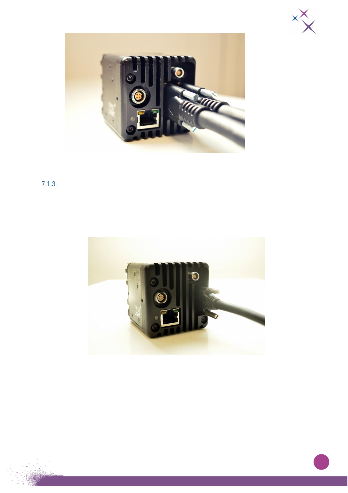
USB connection (for C-RED 3 USB only)
The USB connection is done using a USB-B connector located on the rear side of the camera.
The camera only supports USB 3.0 connection.
Note that USB-A 3.0 compliant connectors are typically blue on standard PC.
Figure 8:
USB3 cable connected plugged in the camera.
To use the camera USB connection, it is strongly recommended to use a Windows®10 PC.
For convenience, drivers for Windows®7 OS are provided, but this OS is not officially supported by First
Light Imaging.
Since Windows®7 does not support USB 3.0 natively, USB 3.0 support is heterogeneous, and
performance is hardly predictable. Please note that First Light Imaging will not provide any support for
issues regarding the use of Windows®7.

19
Also, before using USB3 connection, the C-RED 3 USB3 drivers must be installed on the
PC.
The drivers are included in the USB SDK library. By default, this library is installed with the GUI demo
software. Please simply install the demo software and the drivers will be installed.
Note: To have the full USB3 bandwidth, it is needed for some PC to disable all the energy saving settings
(cf. C-RED 2-3 TS2 disable power saving for USB3). Also, to get the full USB3 bandwidth, it is usually
required to use native USB3 port.
FliVision Graphical User Interface
The Graphical User Interface (GUI) Flivision is provided in the USB key supplied with the C-RED 3
camera, or available on demand at support@first-light.fr.
It is a dedicated interface developed by First Light Imaging which allows to monitor and control all the
parameters of the camera. This software has its own manual.
Powering up/down
Power ON:
When the power FISCHER CONNECTORS is connected to the camera, and the power supply to the line
plug, the camera is ON.
Power OFF:
Please use the CLI command “
shutdown
” from a simple terminal before turning off the camera. First
unplug the power supply from the line plug, then unplug the FISCHER CONNECTORS cable from the
camera.
The shutdown command is recommended (specially to store the latest logs), however, the direct switch
off does not damage it.

20
Camera status
Once the camera is properly powered up by following the steps of section 7, the system boots and C-
RED 3 is ready to operate.
A purple diode signal, visible on the rear face of the camera, confirms the operability.
Camera status
Camera’s led color
Description
Starting
Blue
Camera starting
Configuring
Blue
Camera configuration is applied
Operational
Purple
Camera is operational
Safe Red double blink The camera detects an error. The detector is
turned off. To be able to reuse the camera, you
must restart it.
Prevsafe
Yellow
Locked
Red
The camera detects a critical error. The camera is
unusable, please contact First Light Imaging for
support.
Safe (rescue FW) Orange double blink The camera detects a critical error. The camera is
unusable, please contact First Light Imaging for
support.
Note: turned off led does not necessary mean that there is an issue with the camera. Indeed, the
camera can be configured to switch off the led automatically once boot is completed.
Other manuals for C-RED 3
2
This manual suits for next models
1
Table of contents
Other First Light Lighting Equipment manuals


