First UNI TEMP Series User manual

UNI TEMP
1
Technical data
Electrical data
Supply voltage
With adapter: 230VAC, 50Hz
Without adapter: 24VAC, 50Hz, ± 10% (Cut the
cable connector)
Power consumption
5VA
Connection cable
2
2x0,75mm , length 2m
Sensor type
KTY 81-210 PVC (cable length 1.5m),
insulation: -30°C to 105°C (adapter set enclosed)
Functional data
Torque
max 15Nm
Rotation time
73s/90°
Manual override
Manual or permanent with pushbutton (for maintenance
purposes)
Position indication
Handle position on controller cover
Recommended mounting
position
All positions except upside down
DIP switch settings
1. Direction of rotation (direct CW / inverse CCW)
2. Different temperature ranges depending on the
application (0°C..100°C, 60°C..85°, 20°C..70°C,
25°C..45°C)
3. Reaction factor x1/x10
Safety
Protection class
II
Degree of protection
IP44 (IEC 60529 (2001-02))
Ambient temperature
0..+55°C
Media temperature
According to valve's specifications
Storage temperature
-20°...+80°C
Maintenance
Maintenance-free
Weight
Approx. 0,7kg (without valve)
Enclosed mounting
kit
FIRŠT (ROTOMIX, ROTOMIX G), ESBE (VRG, VRB), ACASO (TERMOMIX), BARBERI,
FEROTERM, PAW, EURONORM, ESBE, IMP, DANFOSS, BESSER, SELTRON, LOVATO,
TUXHORN, STRAWA, CIMBERIO
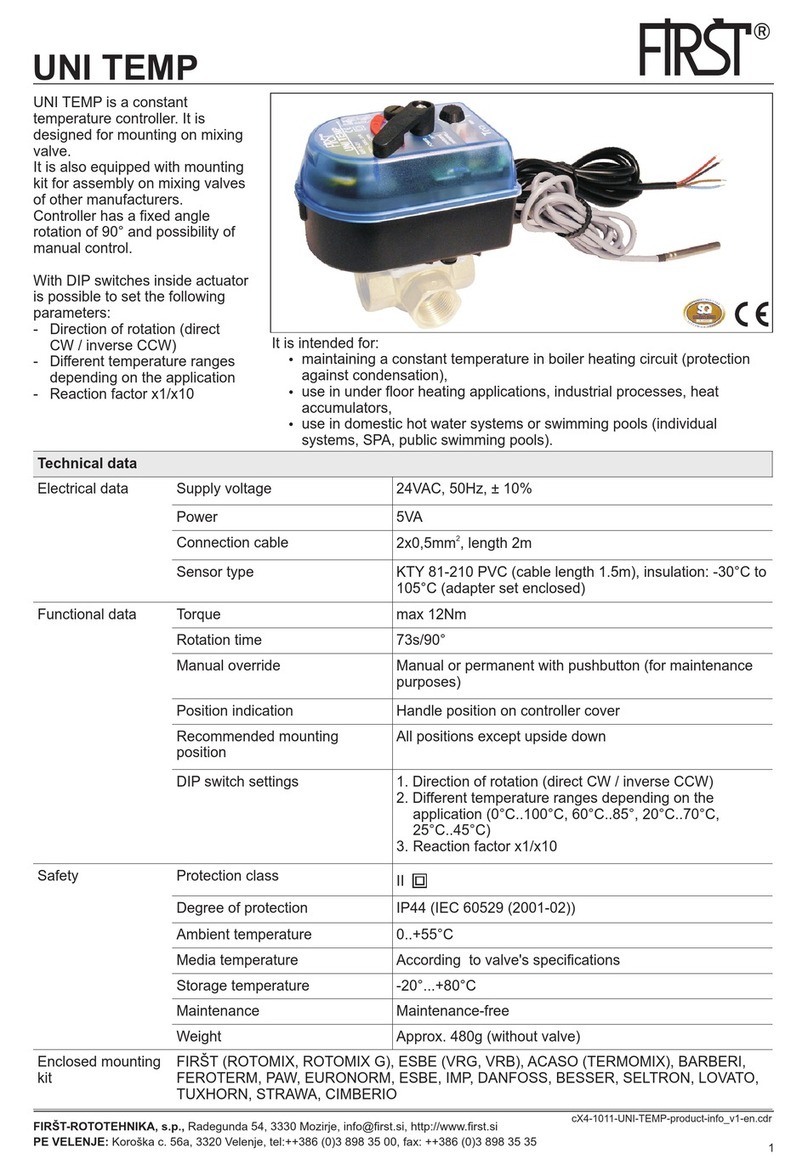
UNI TEMP is a constant
temperature controller. It is
designed for mounting on mixing
valve.
It is also equipped with mounting
kit for assembly on mixing valves
of other manufacturers.
Controller has a fixed angle
rotation of 90° and possibility of
manual control.
With DIP switches inside actuator
is possible to set the following
parameters:
- Direction of rotation (direct
CW / inverse CCW)
- Different temperature ranges
depending on the application
- Reaction factor x1/x10
FIRŠT-ROTOTEHNIKA, s.p., Radegunda 54, 3330 Mozirje, info@first.si, http://www.first.si
PE VELENJE: Koroška c. 56a, 3320 Velenje, tel:++386 (0)3 898 35 00, fax: ++386 (0)3 898 35 35
cX5-2611-UNI-TEMP-product-info_v3-en.cdr
It is intended for:
źmaintaining a constant temperature in boiler heating circuit (protection
against condensation),
źuse in under floor heating applications, industrial processes, heat
accumulators,
źuse in domestic hot water systems or swimming pools (individual
systems, SPA, public swimming pools).
Adapter
230V/24V
24V , 50Hz

www.first.si 2
UNI TEMP UNI TEMP
www.first.si 3
Electrical installation:
Dimensions:
Order information:
Code
Article
Voltage
Time
Torque
21135
UNI TEMP 24VAC
24VAC, 50Hz
73s/90°
max. 15Nm
21136
UNI TEMP 230VAC
230VAC, 50Hz
73s/90°
max. 15Nm
Enclosed mounting kit for following mixing valves: FIRŠT (ROTOMIX, ROTOMIX G), ESBE
(VRG, VRB), ACASO (TERMOMIX), BARBERI, FEROTERM, PAW, EURONORM, ESBE,
IMP, DANFOSS, BESSER, SELTRON, LOVATO, TUXHORN, STRAWA, CIMBERIO.
24V , 50Hz
!
UNI TEMP 24VAC UNI TEMP 230VAC
40
Ø6
l=1,5m
Sensor (VF) KTY81-210
230VAC, 50Hz
!
40
Ø6
Sensor (VF) KTY81-210
The equipment must be connected to the electric power
supply in a manner which coplies with the legal
equirements applicable at the place of use.
24V , 50Hz
brown (L)
blue (N)
Pin terminal
1 2 3 4 5
Cut the cable connector
l=1,5m
Mounting on the valve:
ROTOMIX F3
ROTOMIX F4
1
ESBE VRB, VRG
FIRŠT (ROTOMIX G), ESBE,
(TERMOMIX), BARBERI, FEROTHERM,
PAW, EURONORM, IMP, DANFOSS,
BESSER
ACASO
Mounting kit
Code Enclosed mounting kit
58024
G), ESBE (VRG, VRB),
ACASO (TERMOMIX),
BARBERI, FEROTERM, PAW,
EURONORM, ESBE, IMP,
DANFOSS, BESSER,
SELTRON, LOVATO,
TUXHORN, STRAWA,
CIMBERIO.
By special request
58025 SELTRON, LOVATO, PAW
58026 LAZZARI, LANDIS
58027 HONEYWELL MS
58028 SIEMENS
58029 MUT
58030 W.I.L.B
58031 CENTRA
58032 MEIBES, WITA, OVENTROP,
HOLTER HORA BR80
SMD/SMV
58033 TEHNOPLANT, EXCELSIOR,
KRAMER, DE PALA
FIRŠT (ROTOMIX, ROTOMIX
2
ROTOMIX F3U
ROTOMIX F4U

www.first.si 4
UNI TEMP
1
ON
2 3 4
DIP switch settings
CW
Temperature
range setting
x10
CCW
x1
1
2
3
4
min max
DIP
0°C..100°C
60°C..85°
20°C..70°C
25°C..45°C
2
OFF
OFF
ON
ON
3
OFF
ON
OFF
ON
Temperature range setting
1
ON
2 3 4
Xp parameter
a proportional control
range of valve
UNI TEMP
www.first.si
Manual control:
Note: when the button
for manual operation is
in <MAN> position,
controller stays in
temporary position
irrespective of control
signal.
Controller behavior diagram as a function of temperature:
50
45
45°C 50°C 55°C
55
permanent
valve opening
permanent
valve closing
set temperature
T (°C)
t
closing area
100% opening
100% closing
opening area
T 50
=
set °C
Xp =10K
Xp = 10K
permanent
valve opening
permanent
valve closing
impulse valve
opening
impulse valve
closing
Example:
-Desired temperature: 50 C
-Xp parameter – proportional control range of valve (10K)
°
When the temperature is
less than 45 , controller
gives continuous signal
for opening mixing valve.
°C
When the temperature is
between 45 and 50 ,
controller pulsating
opens mixing valve.
Nearer the desired
temperature (50 ),
shorter pulses.
°C °C
°C
When the temperature is
between 50 and 55 ,
controller pulsating
closes mixing valve.
Nearer the desired
temperature (50 ),
shorter pulses.
°C °C
°C
When the temperature is
higher than 55 ,
controller gives
continuous signal for
closing mixing valve.
°C
Nearer the desired
temperature (50 ),
shorter pulses.
°C
Nearer the desired
temperature (50 ),
shorter pulses.
°C
impulse valve
opening
impulse valve
closing
www.first.si 4
UNI TEMP
Settings:
With DIP switches inside actuator is
possible to set the following
parameters:
DIP 1 Direction of rotation (direct CW /
inverse CCW)
DIP 2,3 Different temperature ranges
depending on the application
(0°C..100°C, 60°C..85°, 20°C..70°C,
25°C..45°C)
DIP 4 Reaction factor
NOTE – when changing DIP1 position,
controller calibration is carried out
ON
1 2 3 4
DIP switch settings
ON
1 2 3 4
LED
COM
Xp
Trimmer Xp is located inside controller.
To open the controller it is necessary to loosen the
screws on the cover (3x), and handle screw (1x).
Xp parameter - a proportional control range of
valve (from 10K to 100K)
Xp parameter - a proportional control range of valve (from 10K to 100K)
1 Mechanical indication.
Indicator can be set according to the valve
assembly
2 Button for manual/auto control
3 Handle for manually controlling the drive, which
also serves for the indication position of the valve
4 Button for adjusting the required temperature.
When adjusting the temperature, the set value
flashes on LCD screen.
5 LED indication of:
- Flash: actuator calibration
- ON: normal operation
6 LCD screen for displaying temperature
7 DIP switches cover
90°

www.first.si 4
UNI TEMP
1
ON
2 3 4
DIP switch settings
CW
Temperature
range setting
x10
CCW
x1
1
2
3
4
min max
DIP
0°C..100°C
60°C..85°
20°C..70°C
25°C..45°C
2
OFF
OFF
ON
ON
3
OFF
ON
OFF
ON
Temperature range setting
1
ON
2 3 4
Xp parameter
a proportional control
range of valve
UNI TEMP
www.first.si
Manual control:
Note: when the button
for manual operation is
in <MAN> position,
controller stays in
temporary position
irrespective of control
signal.
Controller behavior diagram as a function of temperature:
50
45
45°C 50°C 55°C
55
permanent
valve opening
permanent
valve closing
set temperature
T (°C)
t
closing area
100% opening
100% closing
opening area
T 50
=
set °C
Xp =10K
Xp = 10K
permanent
valve opening
permanent
valve closing
impulse valve
opening
impulse valve
closing
Example:
-Desired temperature: 50 C
-Xp parameter – proportional control range of valve (10K)
°
When the temperature is
less than 45 , controller
gives continuous signal
for opening mixing valve.
°C
When the temperature is
between 45 and 50 ,
controller pulsating
opens mixing valve.
Nearer the desired
temperature (50 ),
shorter pulses.
°C °C
°C
When the temperature is
between 50 and 55 ,
controller pulsating
closes mixing valve.
Nearer the desired
temperature (50 ),
shorter pulses.
°C °C
°C
When the temperature is
higher than 55 ,
controller gives
continuous signal for
closing mixing valve.
°C
Nearer the desired
temperature (50 ),
shorter pulses.
°C
Nearer the desired
temperature (50 ),
shorter pulses.
°C
impulse valve
opening
impulse valve
closing
www.first.si 4
UNI TEMP
Settings:
With DIP switches inside actuator is
possible to set the following
parameters:
DIP 1 Direction of rotation (direct CW /
inverse CCW)
DIP 2,3 Different temperature ranges
depending on the application
(0°C..100°C, 60°C..85°, 20°C..70°C,
25°C..45°C)
DIP 4 Reaction factor
NOTE – when changing DIP1 position,
controller calibration is carried out
ON
1 2 3 4
DIP switch settings
ON
1 2 3 4
LED
COM
Xp
Trimmer Xp is located inside controller.
To open the controller it is necessary to loosen the
screws on the cover (3x), and handle screw (1x).
Xp parameter - a proportional control range of
valve (from 10K to 100K)
Xp parameter - a proportional control range of valve (from 10K to 100K)
1 Mechanical indication.
Indicator can be set according to the valve
assembly
2 Button for manual/auto control
3 Handle for manually controlling the drive, which
also serves for the indication position of the valve
4 Button for adjusting the required temperature.
When adjusting the temperature, the set value
flashes on LCD screen.
5 LED indication of:
- Flash: actuator calibration
- ON: normal operation
6 LCD screen for displaying temperature
7 DIP switches cover
90°

www.first.si 6
Solid fuel boiler - Maintain a constant temperature in
heating circuit
M M
Maintain a constant temperature of heat reservoir
UNI TEMP
UNI TEMP
UNI
TEMP
UNI TEMP
UNI TEMP
DTC100/2
M
Examples:
UNI TEMP
M
UNI
TEMP
ROTOTERM
MR-TR
Maintain a constant temperature in
sanitary water circuit
Floor heating - Maintain a
constant temperature of
heating circuit
Solar pool heating - Maintain a constant temperature of
heating circuit
Floor heating regulation
from radiator heating circuit
UNI TEMP UNI TEMP
www.first.si 7
FIRŠT-ROTOTEHNIKA, s.p.,
Radegunda 54, 3330 Mozirje
info@first.si, http://www.first.si
PE VELENJE:
Koroška c. 56a, 3320 Velenje
tel: 03 / 898 35 00, fax: 03 / 898 35 35
In compliance with standards
All our products fulfil the essential safety and protection requirements for CE conformity marking according to the
following directives: EMC directive: 2004/108/EEC / LV directive: 2006/95/EEC / PAH directive 2005/69/EEC.
In compliance with standards:
EN 60730-2-14; 1997 + A1:2001 + A11:2005 + A2:2008
EN60730-1:2000 + A12:2003 + A12:2004 + A14:2005 + A16:2007 + A2:2008
EN 55014-1:2006
EN 61000-3-2:2006
EN 61000-3-3:2006
EN 62233:2008
ZEK 01.2-08
We reserve the right to modify the instructions and the technical data of the product without prior notice.
Safety notes:
źThe actuator has been designed for use in stationary heating, ventilation and air-
conditioning systems and is not allowed to be used outside the specified field of
application, especially in aircraft or in any other airborne means of transport.
źCaution power supply voltage – 24VAC.
źIt may only be installed by suitably trained personnel. All applicable legal or
institutional installation regulations must be complied with.
źThe device must be protected from moisture and is not recommended for use in
external applications.
źThe device may only be opened at the manufacturer's site. It does not contain any
parts that can be replaced or repaired by the user.
źThe cable must not be removed from the device.
źThe device contains electrical and electronic components and is not allowed to be
disposed of as household refuse. All locally valid regulations and requirements
must be observed.
Recommended mounting position
Examples:
This manual suits for next models
2
Other First Temperature Controllers manuals
Popular Temperature Controllers manuals by other brands
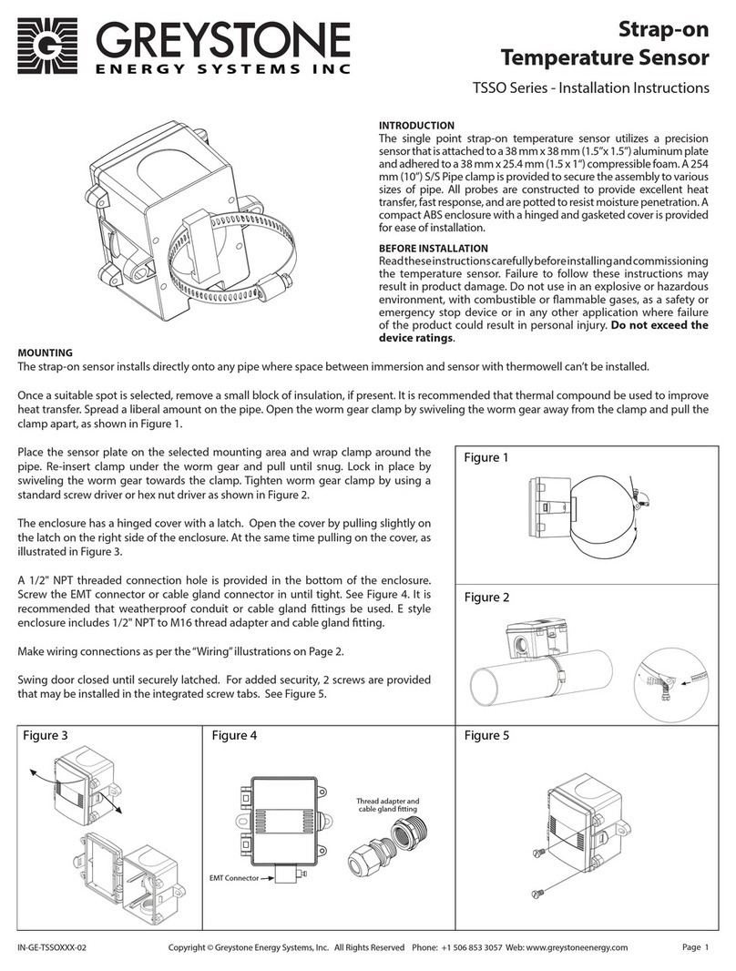
Greystone Energy Systems
Greystone Energy Systems TSSO Series installation instructions
Johnson Controls
Johnson Controls FX-WRZ Series installation instructions
Temperature Guard
Temperature Guard CM712 Manual and installation instructions
Cole Parmer
Cole Parmer FSB-200 Series instruction manual
THERMOSALD
THERMOSALD UPSCR Series Operator's manual
Danfoss
Danfoss ECL Comfort 110 quick guide
