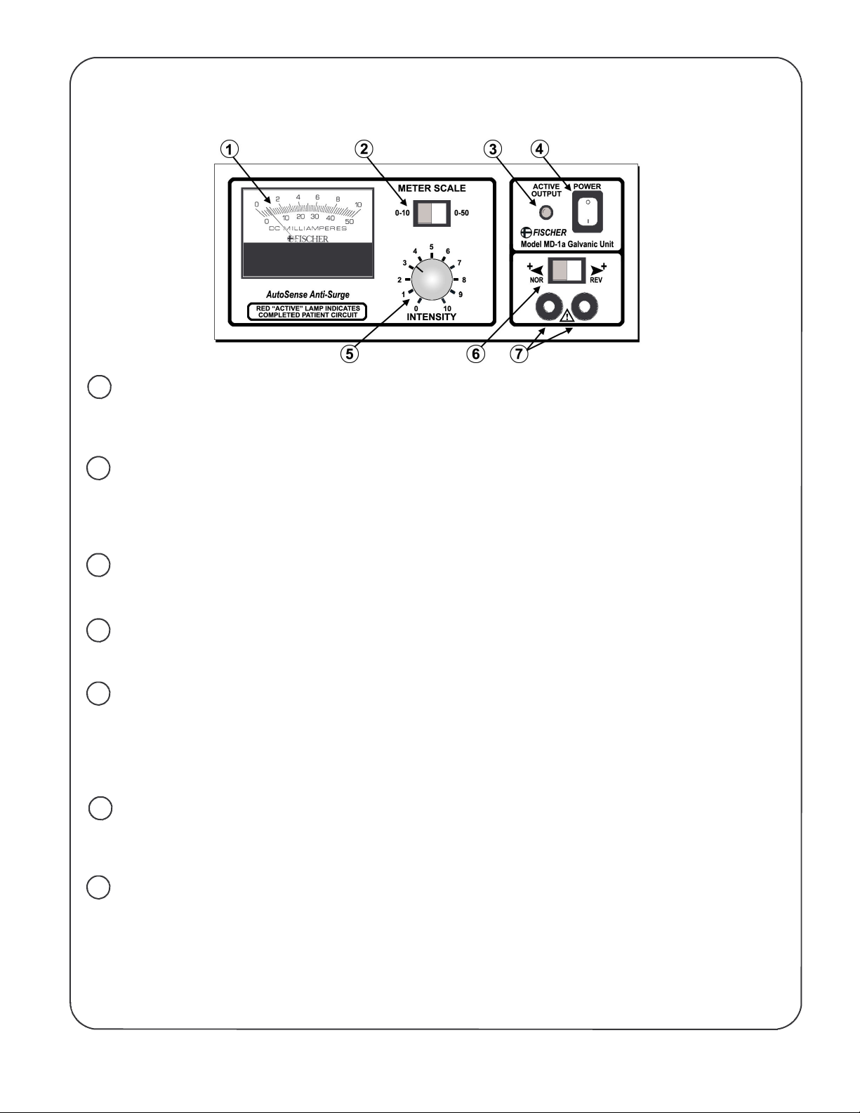
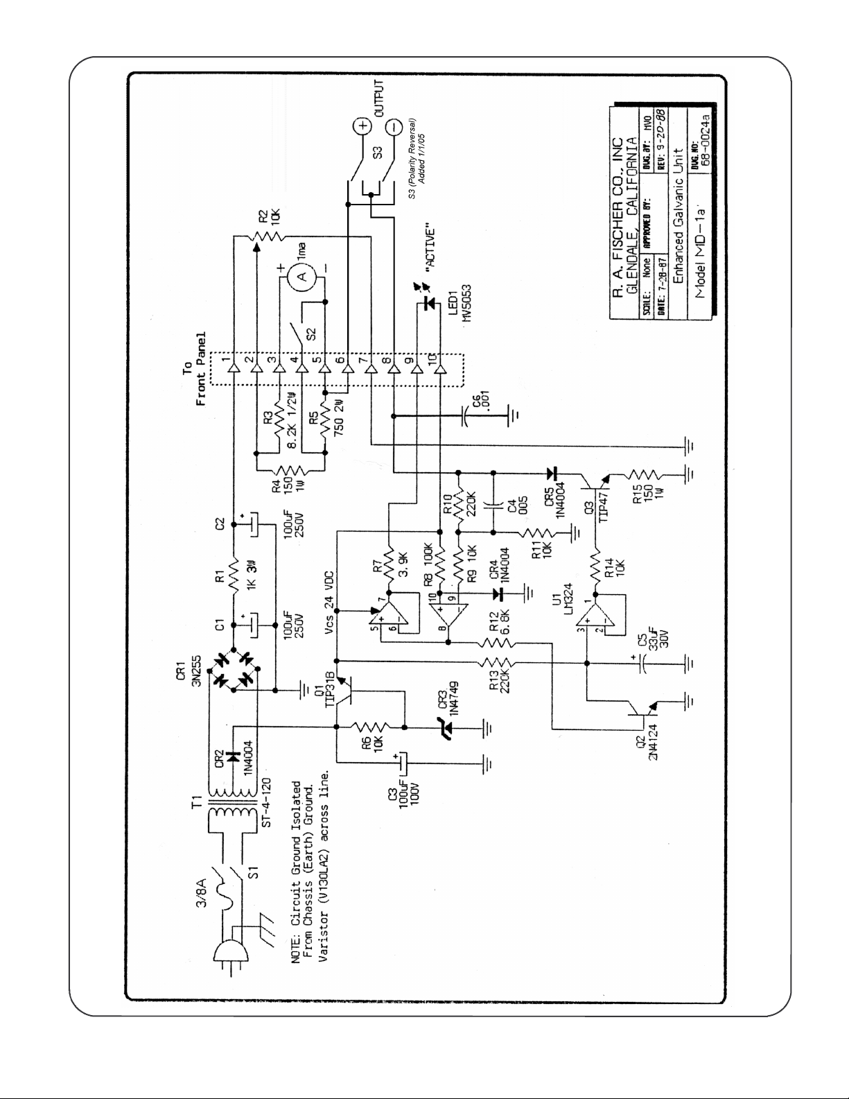
FISCHER MD-1a Product manual


Other FISCHER Measuring Instrument manuals

FISCHER
FISCHER MA15F ... A Series User manual

FISCHER
FISCHER ECO-LINE FT80 User manual

FISCHER
FISCHER ME01 Series Instruction Manual

FISCHER
FISCHER MS11 User manual

FISCHER
FISCHER Me01 Series User manual

FISCHER
FISCHER PERMASCOPE MP0R User manual

FISCHER
FISCHER MMS Inspection DPM User manual

FISCHER
FISCHER DA12 User manual

FISCHER
FISCHER DA30 User manual

FISCHER
FISCHER DAREX 715000 User manual

FISCHER
FISCHER MMS User manual

FISCHER
FISCHER NC56 User manual

FISCHER
FISCHER DA12 User manual

FISCHER
FISCHER DA03 GKT/HLP User manual

FISCHER
FISCHER MS10 User manual

FISCHER
FISCHER DA09 series User manual

FISCHER
FISCHER DA09 series User manual

FISCHER
FISCHER ME49F Series User manual

FISCHER
FISCHER NC57 User manual

FISCHER
FISCHER DELTASCOPE FMP10 User manual


Popular Measuring Instrument manuals by other brands


Extech Instruments
Extech Instruments HD750-NIST user guide

EPA
EPA LW-MK3 Driver installation

Interscan Corporation
Interscan Corporation GasD 8000 Series instruction manual

mPower Electronics
mPower Electronics POLI Service manual

Extech Instruments
Extech Instruments 407738 user guide

VDO
VDO 333.001 FITTING INSTRUCTION