2 | 8 Page
1.5 Unauthorised Modification
Modifications of or other technical alterations to the
instrument by the customer are not permitted. This
also applies to replacement parts. Any modifica-
tions/alterations required will be carried out by
Fischer Mess- und Regeltechnik GmbH only.
1.6 Impermissible modes of operation
The operational safety of this instrument can only
be guaranteed if it is used as intended. The instru-
ment model must be suitable for the medium used
in the system. The limit values given in the technical
data may not be exceeded.
1.7 Safe working practices for mainte-
nance and installation work
The safety instructions given in this operating man-
ual, any nationally applicable regulations on acci-
dent prevention and any of the operating company's
internal work, operating and safety guidelines must
be observed.
The operating company is responsible for ensuring
that all required maintenance, inspection and instal-
lation work is carried out by qualified specialized
personnel.
1.8 Explanation of symbols
WARNING!
… indicates a potentially dangerous
situation, non-observance of which
could endanger persons, animals, the
environment or objects.
INFORMATION!
… highlights important information ef-
ficient and smooth operation.
TIP!
… indicates recommendations that are
not specifically necessary in certain
situations but which could be useful.
2 Application purpose
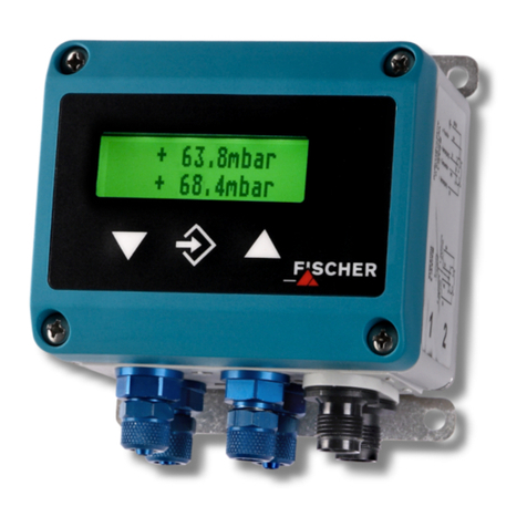
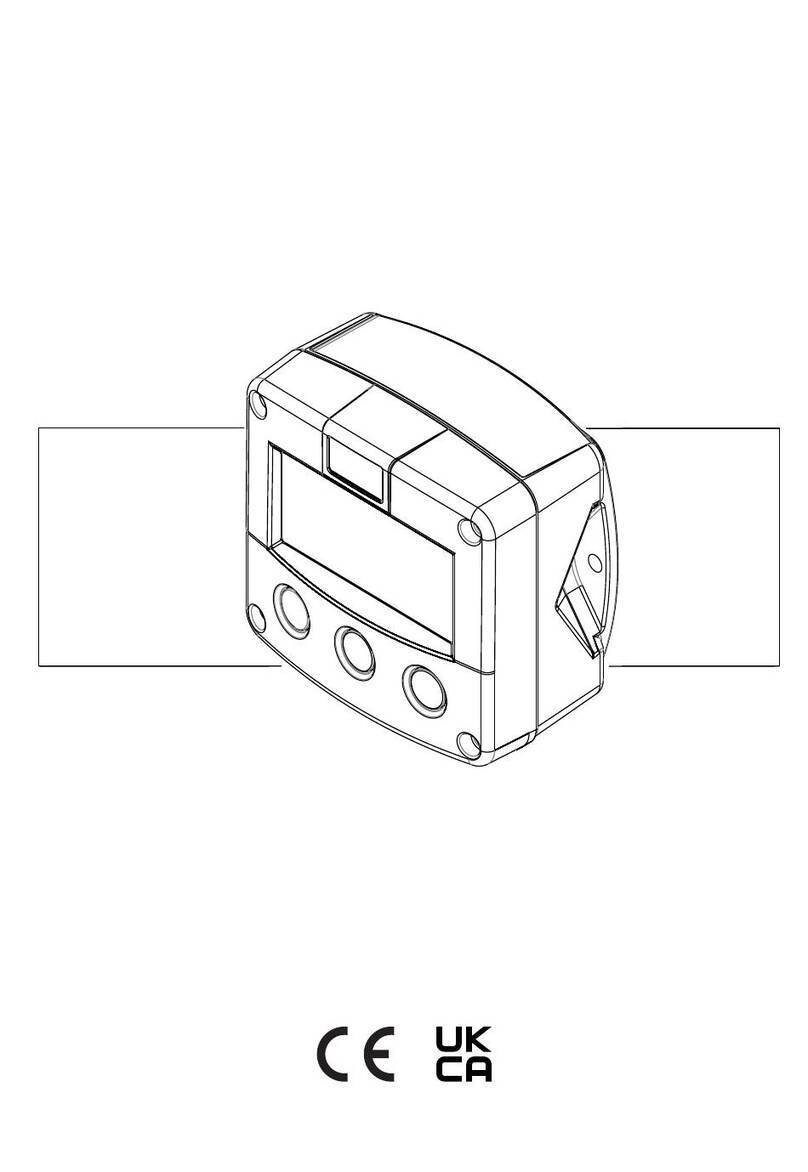
The ME01 is an electronic manometer with a ce-
ramic measuring cell for measuring over-pressure
and under-pressure with a local display and remote
signal transmission.
3 Product and function description
3.1 Design and mode of operation
A ceramic measuring cell acts as the pressure
transducer. The high resistance of the ceramic ma-
terials that are used allow use even for aggressive
media.
There is a resistance measuring bridge attached to
the side of the measuring diaphragm that faces
away from the medium. When pressure is exerted,
the membrane distorts in the elastic range. t the
same time, the resistance values of the bridge
change proportionally to the measuring pressure.
These values are implemented and displayed by
the installed electronics.
There are electrical uniform signals 0/4…20 mA
and 0…10 V in a 3-wire system available for remote
transmission.
4 Installation and assembly
As standard, the device with the connecting port for
connection to pipes and other connection parts,
such as the welding sleeve, union nut with soldering
and welding nipples, is equipped with soldering and
welding nipples (see data sheet MZ...). It can be
mounted to a wall using the wall bracket (see data
sheet MZ...). Manometer screw connections for 10,
8, 6 mm dia. pipes can be supplied for connection
to pipes.
The enclosure protection type IP 65 is only guaran-
teed, if a suitable power supply cable is used.
4.1 Process connection
•By authorized and qualified specialized person-
nel only.
•Only for the designated mechanical process
connection - for the model, see the order code
on the device type plate.
•The pipes need to be depressurized when the
device is being connected.
•Appropriate steps must be taken to protect the
device from pressure surges.
•Check the suitability of the device for the media
to be measured.
•Observe the maximum pressure.
•Check that the pressure connections do not
leak before commissioning.


