2
1.4. Safety Instructions for Operators
Safety instructions for the proper use of this product must
be followed. This information must be available at all
times to personnel responsible for installation, operation,
maintenance and inspection of this product. Adequate
steps must be taken to prevent the occurrence of hazar-
dous conditions that can be caused by electric energy
and the convertible energy of the process media. Such
conditions can, for example, be the result of improper
electrical or process connections. Detailed information is
available in relevant published norms (DIN EN, UVW in
Germany; and equivalents in other countries), industrial
standards such as DVWG, Ex-, GL-, VDE guidelines, as
well as regulations of the local authorities (e.g., EVUs in
Germany).
1.5. Modifications Forbidden
Modification or other technical alteration of the product is
not permissible. This also applies to the use of unautho-
rized spare parts for repair / maintenance of the product.
Any modifications to this product, if and as necessary,
should be done only by Fischer Mess- und Regeltechnik
GmbH.
1.6. Operational Restrictions
The operational reliability of the product is guaranteed
only when used for intended purposes. The product must
be selected and configured for use specifically with defi-
ned process media. The limiting values of operating pa-
rameters, as given in the product specification sheet,
must never be crossed.
1.7. Safety Considerations during Installation and
Maintenance
The safety instructions given in this manual, existing na-
tional regulations relating to accident prevention and the
internal safety rules and procedures of the user organi-
zation regarding safety during installation, operation and
servicing must all be followed meticulously.
It is the responsibility of the users to ensure that only sui-
tably qualified and experienced technical personnel are
used for installation, operation and servicing of this
equipment.
2. Intended Applications
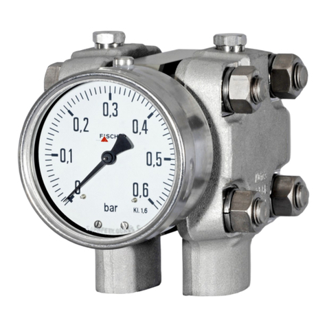
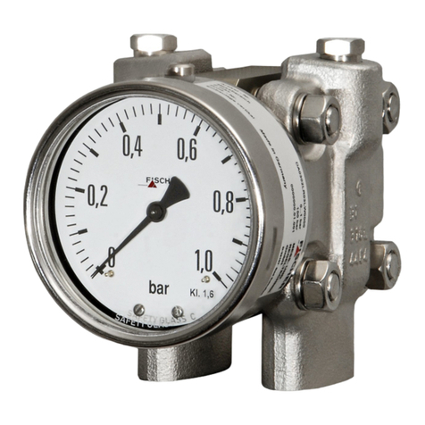
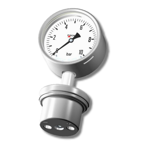
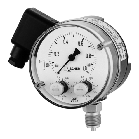
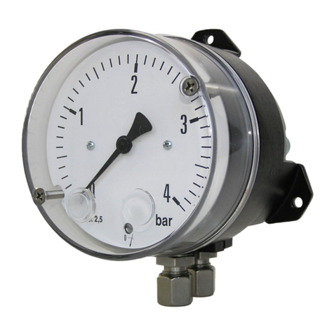
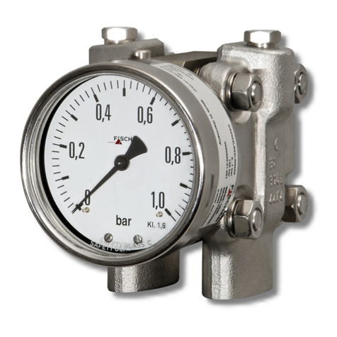
The DA30 measures and indicates pressure and diffe-
rential pressure. It is suitable to work with gaseous and
liquid media not affecting the materials used. Electrical
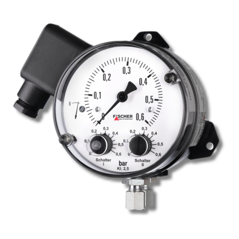
andelectronicaccessory components(KE...)enablelimi-
ting of signal and transmitting of measurement.
The product must be used only for applications and un-
der conditions specified by the manufacturer.
3. Product Description and Functions
3.1. Schematic Diagram
3.2. Principles of Operation
The DA30 is based on a rugged and uncomplicated dia-
phragm movement, suitable for pressure and differential
pressure measurements.
Operating principle of system is identical for all applicati-
ons of this type. In a state of equilibrium,forces of springs
on both sides of the diaphragm are balanced. The pres-
sure or differential pressure to be measured creates an
unbalanced force of springs for the measuring range until
a new equilibrium is reached. When subjected to exces-
sive pressure, the diaphragm rests on metal supporting
plates. A centre-mounted torque rod transfers motion of
the diaphragm system by an eccentric tilted axle through
a torsional socket outwards.
The axle rotation is transmitted to the dial by a lever.
4. Installation
Types with inbuilt limit switches need matching connec-
tion to fixed cable connection to guarantee protection
class IP65. Its outer diameter needs to be between 7 and
13 mm.
The instrument is intended and factory adjusted for verti-
cal mounting (wall mounting), pressure ports downward.
When mounted in other orientation (max. ± 10W°) the
pointers’ zero position needs to be adjusted (see 5.2).
3
4
2
6
1
5
1
1 Measuring springs
2 Torsional socket
3 Dial
4 Lever
5 Diaphragm
6 Torque rod


