2
1.5. Modifications Forbidden
Modification or other technical alteration of the product is
not permissible. This also applies to the use of unautho-
rized spare parts for repair / maintenance of the product.
Any modifications to this product, if and as necessary,
should be done only by Fischer Mess- und Regeltechnik
GmbH.
1.6. Operational Restrictions
The operational reliability of the product is guaranteed
only when used for intended purposes. The product must
be selected and configured for use specifically with defi-
ned process media. The limiting values of operating pa-
rameters, as given in the product specification sheet,
must never be crossed.
1.7. Safety Considerations during Installation and
Maintenance
The safety instructions given in this manual, existing na-
tional regulations relating to accident prevention, and the
internal safety rules and procedures of the user organi-
zation regarding safety during installation, operation and
servicing must all be followed meticulously.
It is the responsibility of the users to ensure that only sui-
tably qualified and experienced technical personnel are
used for installation, operation and servicing of this
equipment.
2. Intended Applications
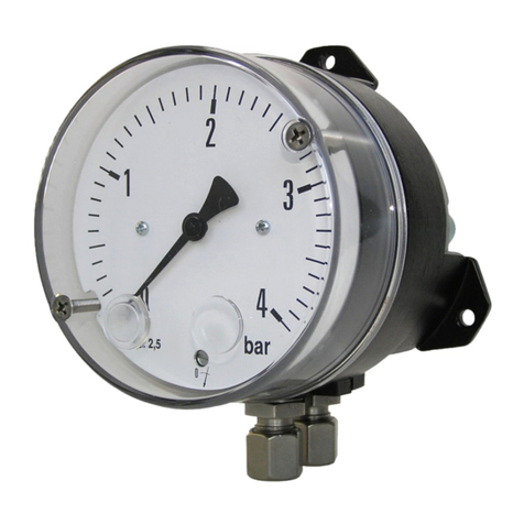
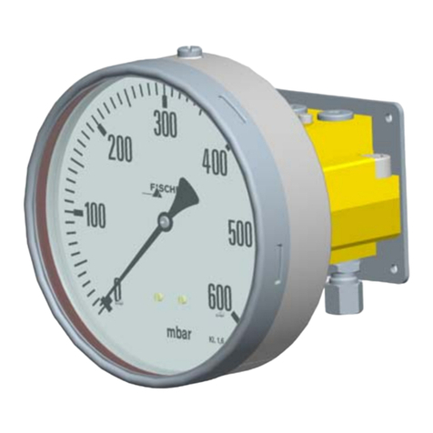
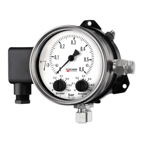
The contact pressure gauge MS11 is a combined
measuring and switching instrument for usage in difficult
measuring conditions like pressure surges, vibrations,
frequent switching actions or high demands on breaking
capacity. The product must be used only for applications
and under conditions specified by Fischer Mess- und Re-
geltechnik GmbH.
Please confer with Fischer Mess- und Regeltechnik
GmbH prior to using this instrument along with polluted
or aggressive media. For use with this media it needs to
be adapted in every part with direct contact to the media.
3. Product Description and Functions
3.1. Schematic Diagram
3.2. Principles of Operation
This pressure instrument is based on a rugged and un-
complicated diaphragm movement, suitable for over-
pressure- and partial vacuum pressure measurements.
In non-operative state, forces of springs on both sides of
diaphragm are balanced. Pressure or differential pressu-
re to be measured creates an unbalanced force of
springs for measuring range until a new balance is rea-
ched. When subjected to excessive pressure, diaphragm
rests on metal supporting plates. A centre-mounted tap-
pet transfers motion of the diaphragm system to indicator
movement and operating elements of micro switches.
4. Installation
The instrument is intended for pipework mounting using
a pressure connection shank per DIN EN 837 by default.
Optional it can be wall-mounted by 3 fastening elements
casted on housing. The instrument is factory calibrated
while mounted upright, pressure port downward.
To ensure safety during installation and maintenance in-
tegrate adequate shut-off valves. By recommended ac-
cessories (see 9.) the instrument can be
• depressurized or shut down,
• cut off a plant to enable controlling or repairing,
• operational checked on site.
4.1. Process Connections
• Only qualified technicians authorized for this type of
work should undertake installation.
• Only for intended mechanical process connection
(for model information see ordering code on type pla-
te of instrument).
• Ensure that process equipment and pressure lines
are at atmospheric pressure before making pressure
connections.
• The instrument should be provided with suitable pro-
tection against pressure surges (e.g., snubber or pul-
sation damper).
• Ensure that the mechanical configuration and materi-
als of construction of the instrument are compatible
with the process media.
• Ensure that process pressure is always less than the
specified safe pressure rating.
4.2. Electrical Connections
• Only qualified technicians authorized for this type of
work should undertake installation.
• Switch off electrical power to the plant before attemp-
ting electrical installation work of any kind.
• Electrical connections must comply with relevant in-
ternational, national and local regulations and norms
relating to electrical and instrumentation installations.
1. Pressure chamber
2. Motion work
3. Tappet
4. Micro switches, opera-
ting elements
5. Measuring springs
6. Measuring diaphragm


