2
1.4. Safety Instructions for Operators
Safety instructions for the proper use of this product must
be followed. This information must be available at all times
to personnel responsible for installation, operation, main-
tenance and inspection of this product. Adequate steps
must be taken to prevent the occurrence of hazardous
conditions that can be caused by electric energy and the
convertible energy of the process media. Such conditions
can, for example, be the result of improper electrical or
process connections. Detailed information is available in
relevant published norms (DIN EN, UVW in Germany;
and equivalents in other countries), industrial standards
such as DVWG, GL-, VDE guidelines, as well as regula-
tions of the local authorities (e.g., EVUs in Germany).
1.5. Modifications Forbidden
Modification or other technical alteration of the product is
not permissible. This also applies to the use of unautho-
rized spare parts for repair / maintenance of the product.
Any modifications to this product, if and as necessary,
should be done only by Fischer Mess- und Regeltechnik
GmbH.
1.6. Operational Restrictions
The operational reliability of the product is guaranteed
only when used for intended purposes. The product must
be selected and configured for use specifically with
defined process media. The limiting values of operating
parameters, as given in the product specification sheet,
must never be crossed.
1.7. Safety Considerations during Installation and
Maintenance
The safety instructions given in this manual, existing na-
tional regulations relating to accident prevention and the
internal safety rules and procedures of the user organiza-
tion regarding safety during installation, operation and
servicing must all be followed meticulously.
It is the responsibility of the users to ensure that only su-
itably qualified and experienced technical personnel are
used for installation, operation and servicing of this equip-
ment.
2. Intended Applications
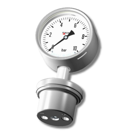
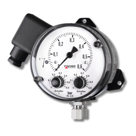
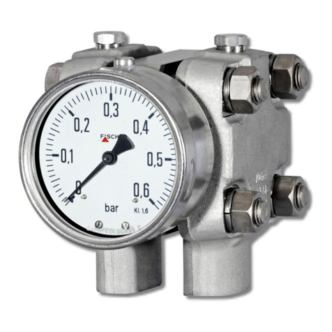
Overpressure and vacuum proof contact pressure gauge
for control and supervising purposes in vacuum proces-
ses.
The product must be used only for applications and under
conditions specified by Fischer Mess- und Regeltechnik
GmbH.
Please confer with Fischer Mess- und Regeltechnik
GmbH prior to using this instrument along with polluted or
aggressive media. For use with this media it needs to be
adapted in every part with direct contact to the media.
3. Product Description and Functions
3.1. Schematic Diagram
3.2. Principles of Operation
The measuring system consists of two encapsulated and
hydraulically coupled metal diaphragm. When subjected
to pressure it causes a deflection proportional to the
strength of pressure. Opposite of the medium-touched
diaphragm a tappet returns the deflection to a motion work
and the operating elements of the micro switches.
When subjected to excessive pressure each metal dia-
phragm based oneself on the chassis of the capsule.
Therefore the device is prevented from damage.
4. Installation
The instrument is intended for pipe mounting by KF10
small flange pipe connection per DIN 28403 / ISO 2861.
The instrument is factory calibrated while mounted up-
right, pressure port downward and must be mounted that
way.
To ensure safety during installation and maintenance in-
tegrate adequate shut-off valves. By recommended
accessories the instrument can be
• depressurized or shut down,
• cut off a plant to enable controlling or repairing,
• operational checked on site.
1. Measuring diaphragm
2. Motion work
3. Tappet
4. Micro switches,
Operating elements
5. Pressure chamber


