FISCHER ER76 User manual

Operating manual
ER76
Control relay for level probes
DNV-GL version
09015289 • BA_EN_ER76 • Rev. ST4-D • 10/23
*09015289*
| Masthead FISCHER Mess- und Regeltechnik GmbH
2/20 BA_EN_ER76
Masthead
Manufacturer: FISCHER Mess- und Regeltechnik GmbH
Bielefelderstr. 37a
D-32107 Bad Salzuflen
Telephone: +49 5222 974 0
Telefax: +49 5222 7170
eMail: [email protected]
web: www.fischermesstechnik.de
Technical editorial team: Documentation representative: T. Malischewski
Technical editor: R. Kleemann
All rights, also those to the translation, reserved. No part of this document may
be reproduced or processed, duplicated or distributed using electronic systems
or any other form (print, photocopy, microfilm or another process) without the
written consent of the company FISCHER Mess- und Regeltechnik GmbH, Bad
Salzuflen.
Reproduction for internal use is expressly allowed.
Brand names and procedures are used for information purposes only and do
not take the respective patent situation into account. Great care was taken
when compiling the texts and illustrations; Nevertheless, errors cannot be ruled
out. The company FISCHER Mess- und Regeltechnik GmbH will not accept any
legal responsibility or liability for this.
Subject to technical amendments.
© FISCHER Mess- und Regeltechnik 2020
Version history
Rev. ST4-A 10/20 Version 1 (first edition)
Rev. ST4-B 04/21 Version 2 (new housing)
Rev. ST4-C 07/21 Version 3 (CE declaration updated)
Rev. ST4-D 10/23 Version 4 (DNV certificate updated)

FISCHER Mess- und Regeltechnik GmbH Table of contents
BA_EN_ER76 3/20
Table of contents
1 Safety instructions.......................................................................................................... 4
1.1 General................................................................................................................................... 4
1.2 Personnel Qualification .......................................................................................................... 4
1.3 Risks due to Non-Observance of Safety Instructions............................................................. 4
1.4 Safety Instructions for the Operating Company and the Operator ......................................... 4
1.5 Unauthorised Modification...................................................................................................... 4
1.6 Inadmissible Modes of Operation........................................................................................... 4
1.7 Safe working practices for maintenance and installation work............................................... 5
1.8 Pictogram explanation............................................................................................................ 5
2 Product and functional description............................................................................... 6
2.1 Delivery scope........................................................................................................................ 6
2.2 Device versions ...................................................................................................................... 6
2.3 Intended use........................................................................................................................... 7
2.4 Function diagram.................................................................................................................... 7
2.5 Design and mode of operation ............................................................................................... 8
3 Assembly ......................................................................................................................... 9
3.1 General................................................................................................................................... 9
3.2 Electrical connection .............................................................................................................. 9
4 Start-up ............................................................................................................................ 11
5 Servicing .......................................................................................................................... 12
5.1 Maintenance........................................................................................................................... 12
5.2 Transport ................................................................................................................................ 12
5.3 Service ................................................................................................................................... 12
5.4 Disposal.................................................................................................................................. 12
6 Technical data ................................................................................................................. 13
6.1 General................................................................................................................................... 13
6.2 Input variables ........................................................................................................................ 13
6.3 Output sizes ........................................................................................................................... 13
6.4 Auxiliary energy...................................................................................................................... 13
6.5 Operating conditions .............................................................................................................. 13
6.6 Construction design................................................................................................................ 14
7 Order codes ..................................................................................................................... 15
7.1 Accessories ............................................................................................................................ 15
8 Attachment ...................................................................................................................... 16

1 | Safety instructions FISCHER Mess- und Regeltechnik GmbH
4/20 BA_EN_ER76
1 Safety instructions
1.1 General
This operating manual contains basic instructions for the installation, operation
and maintenance of the device that must be followed without fail. It must be
read by the installer, the operator and the responsible specialist personnel be-
fore installing and commissioning the device.
This operating manual is an integral part of the product and therefore needs to
be kept close to the instrument in a place that is accessible at all times to the re-
sponsible personnel.
The following sections, in particular instructions about the assembly, commis-
sioning and maintenance, contain important information, non-observance of
which could pose a threat to humans, animals, the environment and property.
The instrument described in these operating instructions is designed and manu-
factured in line with the state of the art and good engineering practice.
1.2 Personnel Qualification
The instrument may only be installed and commissioned by specialized person-
nel familiar with the installation, commissioning and operation of this product.
Specialized personnel are persons who can assess the work they have been
assigned and recognize potential dangers by virtue of their specialized training,
their skills and experience and their knowledge of the pertinent standards.
1.3 Risks due to Non-Observance of Safety Instructions
Non-observance of these safety instructions, the intended use of the device or
the limit values given in the technical specifications can be hazardous or cause
harm to persons, the environment or the plant itself.
The supplier of the equipment will not be liable for damage claims if this should
happen.
1.4 Safety Instructions for the Operating Company and the
Operator
The safety instructions governing correct operation of theinstrument must be
observed. The operating company must make them available to the installation,
maintenance, inspection and operating personnel.
Dangers arising from electrical components, energy discharged by the medium,
escaping medium and incorrect installation of the device must be eliminated.
See the information in the applicable national and international regulations.
Please observe the information about certification and approvals in the Tech-
nical Data section.
1.5 Unauthorised Modification
Modifications of or other technical alterations to the instrument by the customer
are not permitted. This also applies to replacement parts. Only the manufacturer
is authorised to make any modifications or changes.
1.6 Inadmissible Modes of Operation
The operational safety of this instrument can only be guaranteed if it is used as
intended. The instrument model must be suitable for the medium used in the
system. The limit values given in the technical data may not be exceeded.
The manufacturer is not liable for damage resulting from improper or incorrect
use.
FISCHER Mess- und Regeltechnik GmbH Safety instructions | 1
BA_EN_ER76 5/20
1.7 Safe working practices for maintenance and installation work
The safety instructions given in this operating manual, any nationally applicable
regulations on accident prevention and any of the operating company's internal
work, operating and safety guidelines must be observed.
The operating company is responsible for ensuring that all required mainten-
ance, inspection and installation work is carried out by qualified specialized per-
sonnel.
1.8 Pictogram explanation
DANGER
Type and source of danger
This indicates a direct dangerous situation that could lead to death or serious
injury (highest danger level).
1. Avoid danger by observing the valid safety regulations.
WARNING
Type and source of danger
This indicates a potentially dangerous situation that could lead to death or ser-
ious injury (medium danger level).
1. Avoid danger by observing the valid safety regulations.
CAUTION
Type and source of danger
This indicates a potentially dangerous situation that could lead to slight or seri-
ous injury, damage or environmental pollution (low danger level).
1. Avoid danger by observing the valid safety regulations.
NOTICE
Note / advice
This indicates useful information of advice for efficient and smooth operation.

2 | Product and functional description FISCHER Mess- und Regeltechnik GmbH
6/20 BA_EN_ER76
2 Product and functional description
2.1 Delivery scope
• ER76 according to specification (see order code)
• Operating Manual
2.2 Device versions
Probe connection Probe connection 1+2
Status LED 1+2
1 Channel 2 Channel
Status LED
Supply
Switching output
Supply
Switching output 1+2
Fig.1: Device versions
Bestellnummer Switch output Supply Ub
ER76 1 000000 1 1 relay contact 230 V AC
ER76 1 000000 4 1 relay contact 24 V AC
ER76 2 000000 1 2 relay contacts 230 V AC
ER76 2 000000 4 2 relay contacts 24 V AC
2.2.1 Type plate
This type plate serves as an example of the information that is stated. The data
shown is purely fictive, but does correspond to the actual conditions. For more
information, please see the order code at the end of these instructions.
Art. No.
Supply
Power
Input
Function
Load data
Temp. range
Prod.-Nr.
ER7610000001
230 VAC 50/60 Hz
max. 5 VA
0 ... 200 kOhm
interval
250 VA
-10 .... +70 °C
2106821.00.002
FISCHER Mess- und Regeltechnik GmbH Bielefelder Str. 37a D32107-Bad Salzuflen
Order codes
Serial number
Technical data
Fig.2: Type plate
FISCHER Mess- und Regeltechnik GmbH Product and functional description | 2
BA_EN_ER76 7/20
2.3 Intended use
Control relay ER76 can be used in connection with type NK06 level probes for
the automatically controlling and regulating conductive liquid filling levels in tank
systems.
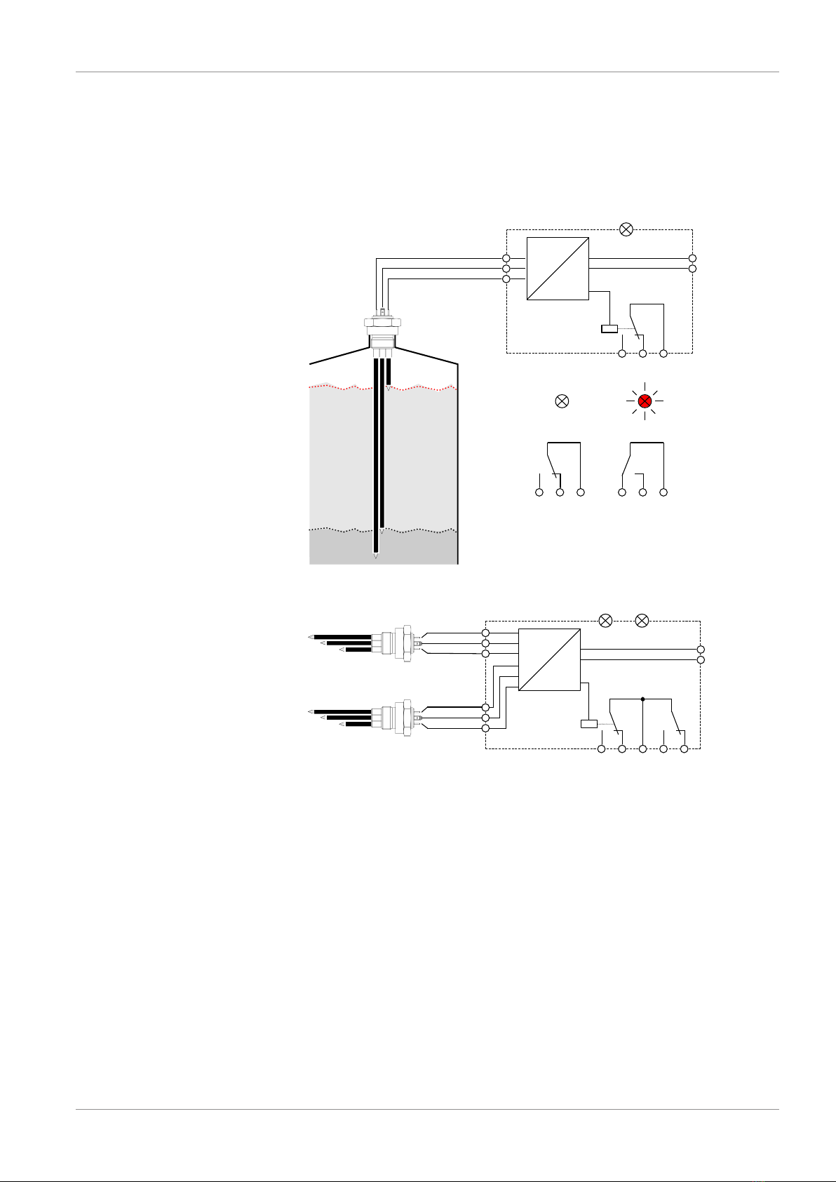
2.4 Function diagram
min
max
NK06
com
max
min 230 V AC
24 V AC
2
3
1
ER76 1 ...
L
N
-K1
K1
Rest position Working contact
ER76 2 ...
com1
L
N
max1
min1
230 V AC
24 V AC
K1 K2
com2
max2
min2
NK06
-K1 -K2
Container 1
Container 2
Fig.3: Function diagram

2 | Product and functional description FISCHER Mess- und Regeltechnik GmbH
8/20 BA_EN_ER76
2.5 Design and mode of operation
ER76 is controlled by the medium using a type NK06 probe. Input sensitivity is
factory-adjusted to 70 kΩ. In order for the relay to switch properly, the medium-
conductivity must not fall below a value of 14µS/cm.
When contact is made, an alternating voltage without a direct voltage compon-
ent flows through the medium, preventing galvanic erosion of the probe mater-
ial.
Depending on the application, location or national regulations, the control elec-
trodes' reference potential can be represented by a common electrode as well
as by the container itself.
After the level probe has been installed and the control relay has been electric-
ally connected, the contact switches to the working position. LED is on.
If the maximum level is reached, the output relay switches to the rest position.
LED is off. This state remains until the level falls below the minimum level and
the contact switches to the working position again.
If the supply voltage fails, there is a defect in the control circuit or an interruption
in the measuring line, the system goes into the safe state (normally closed con-
tact) and thus prevents the container from being overfilled.

FISCHER Mess- und Regeltechnik GmbH Assembly | 3
BA_EN_ER76 9/20
3 Assembly
3.1 General
CAUTION
Risks connected to medium or system
The builder or operator of the tank system must take suitable protective meas-
ures for installation and maintenance.
3.2 Electrical connection
• By authorized and qualified specialized personnel only.
• When connecting the unit, the national and international electro-technical
regulations must be observed.
• Disconnect the system from the mains, before electrically connecting the
device.
• Install the consumer-adapted fuses.
• Do not connect the connector if strained.
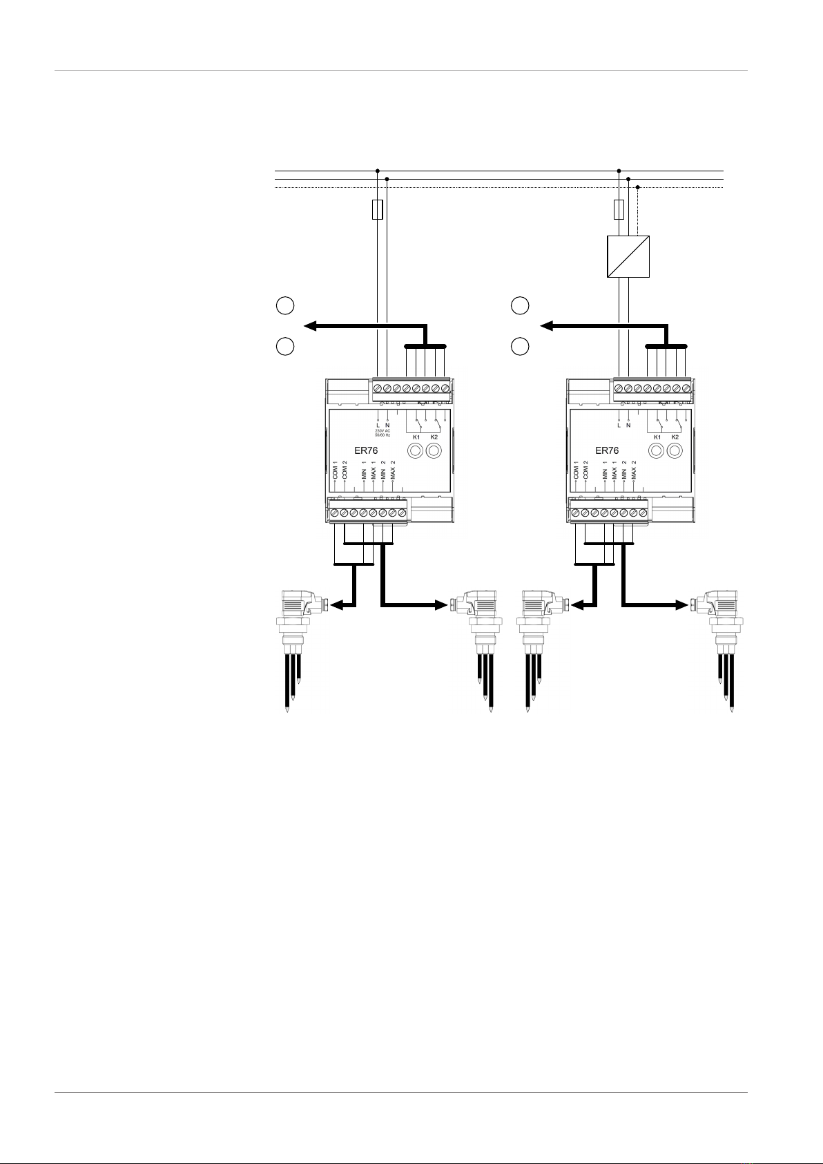
3.2.1 ER76 with one relay
L1
N
PE
F
M
24 V AC
230 V AC
F
NK06 NK06
M
Pump Pump
230 V AC 24 V AC
24 V AC
Fig.4: Automatic level control with a relay (example)
3 | Assembly FISCHER Mess- und Regeltechnik GmbH
10/20 BA_EN_ER76
ER76 switch output does not necessarily have to be used for direct pump con-
trol. It can also be used as a monitoring signal for an electronic control system.
3.2.2 ER76 with two relays
L1
N
PE
F
M1
24 V AC
230 V AC
F
NK06
Pumps
230 V AC 24 V AC
24 V AC
NK06
Tank 2Tank 1
NK06 NK06
Tank 2Tank 1
M2
M1
Pumps
M2
Fig.5: Automatic level control with two relays (example)
With the ER762… two containers can be monitored with one relay. One pos-
sible application would be, for example, controlling a tank for crude oil dewater-
ing and a storage tank for separated water at the same time.
Here, too, switch outputs can be used as monitoring signals for an electronic
control system.
Table of contents


