manuals.online logo
Brands
  1. Home
  2. •
  3. Brands
  4. •
  5. Circutor
  6. •
  7. Relay
  8. •
  9. Circutor RGU-10C User manual

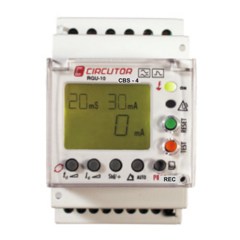
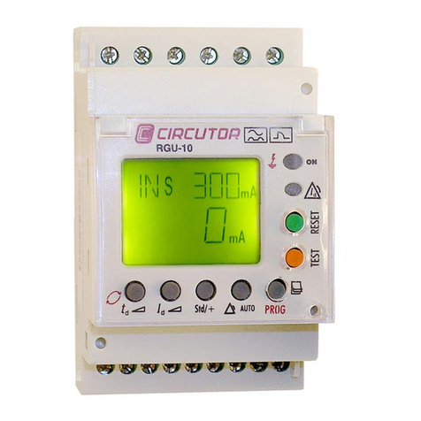
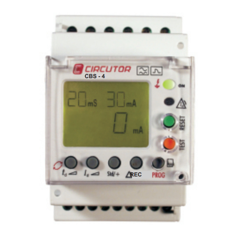
Circutor RGU-10C User manual

Code
code
Type
Type
Sensibilité
Sensivity
Délai de déclenchement
Tripping delay
Communications
Communications
P11944 RGU - 10C
0,03-0,1-0,3-0,5-1-3
par réglage direct
by direct setting
5-10-30 par/by SETUP
INS-SEL-0,02-0,1-0,2-0,3-0,4-0,5-0,75-1
/ by direct settingpar réglage direct
3-5-10 par/by SETUP
Disponible
available
P 1 X X X X 0 0 X
Code
Code
Code interne
Internal code
Tension
d'alimentation
Power supply
230 V c.a.
110 V c.a.
0
1
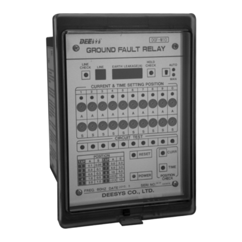
Relais de protection différentielle électronique RGU-10C
RGU-10C Electronic Earth-leakage Protection Relay
Par exemple RGU-10C 110 V c.a / For instance RGU-10C 110 V a.c...alimenté à supplied by
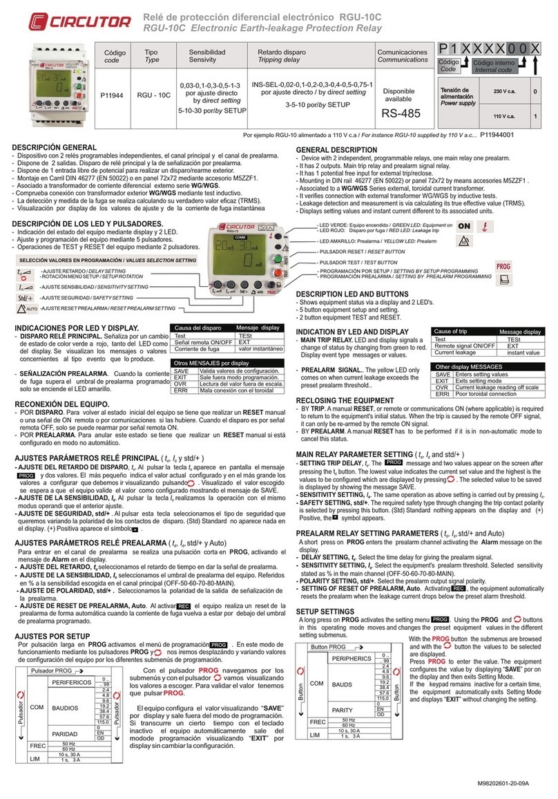
DESCRIPTION GÉNÉRALE
Dispositif avec 2 relais programmables indépendants, le canal principal et le canal de pré-alarme.-Dispose de 2 sorties, déclenchement du relais principal et signalisation par pré-alarme.-Dispose d'1 entrée hors tension pour le déclenchement / réarmement extérieur.-Montage sur rail DIN 46277 (EN 50022) ou sur panneau 72x72 à l'aide de l'accessoire M5ZZF1.-Associé à un transformateur de courant différentiel externe série WGC-Vérifie la connexion avec le transformateur extérieur WGC par test inductif.-La détection et mesure de la fuite sont réalisées en calculant sa vraie valeur efficace (TRMS).-Visualisation sur écran des valeurs de réglage et du courant de fuite instantané-
DESCRIPTION DES LED ET DES BOUTONS.
Indication de l'état de l'appareil sur l'écran et par 2 LEDs.-Réglage et programmation de l'appareil à l'aide de 5 boutons.-Opérations de TEST et RESET de l'appareil à l'aide de 2 boutons.-
I LEDNDICATIONS PAR ET À L'ÉCRAN
- DÉCLENCHEMENT RELAIS PRINCIPAL
Signalisation par changement d'état de couleur verte à
rouge, tant de la DEL que de l'écran. Visualisation des
messages ou valeurs concernant le type d'événement
qui en est à l'origine.
- SIGNALISATION PRÉ-ALARME.
Lorsque le courant de fuite dépasse le niveau de
pré-alarme programmé, seule la DEL jaune s'allume.
RECONNEXION DE L'APPAREIL.
EN CAS DE DÉCLENCHEMENT. Pour revenir à l'état initial de l'appareil, il faut effectuer un -
RESET manuel ou un signal ON à distance ou par communications le cas échéant. Lorsque le
déclenchement est provoqué par un signal à distance OFF, on ne peut réarmer qu'à travers un signal
à distance ON.
-EN CAS DE PRÉ-ALARME. Pour annuler cet état, il faut effectuer un RESET manuel s'il est
configuré en mode non automatique.
RÉGLAGES PARAMÈTRES RELAIS PRINCIPAL (td, id et std/+)
-RÉGLAGE DU DÉLAI DU DÉCLENCHEMENT, td. Lorsque l'on presse le bouton td, le message
PROG et deux valeurs apparaissent à l'écran. La plus petite indique la valeur actuelle configurée et
la plus grande, les valeurs à configurer que nous devons visualiser par pressions successives sur .
Une fois la valeur choisie visualisée, nous attendons que l'appareil valide la valeur comme
configurée en affichant le message SAVE.
-RÉGLAGE DE LA SENSIBILITÉ, Id. Lorsque l'on presse la touche Id, nous réalisons l'opération de la
même manière que pour le réglage précédent.
-RÉGLAGE DE SÉCURITÉ, std/+ Lorsque l'on presse cette touche, nous sélectionnons le type de
sécurité que nous désirons en modifiant la polarité des contacts de déclenchement. (Std) Standard,
rien n'apparaît à l'écran. (+) Positif le symbole + apparaît.
RÉGLAGES PARAMÈTRES RELAIS PRÉ-ALARME (td, Id, std+ et Auto)
Pour entrer dans le canal de pré-alarme, nous appuyons brièvement sur active le PROG, ce qui
message d'Alarme à l'écran.
-RÉGLAGE DU DÉLAI, td Nous choisissons le délai dans l'envoi du signal de pré-alarme.
-RÉGLAGE DE LA SENSIBILITÉ, Id Nous choisissons le seuil de pré-alarme de l'appareil. Indiqué
en % de la sensibilité choisie dans le canal principal (OFF-50-60-70-80-MAIN).
-RÉGLAGE DE POLARITÉ, std/+. Nous sélectionnons la polarité de la sortie de signalisation de la
pré-alarme.
- RÉGLAGE DE RESET DE PRÉALARME, Auto. Lorsque nous activons REC , l' appareil réalise
un reset automatique de la pré-alarme lorsque le courant de fuite revient sous le seuil de pré-alarme
programmé.
RÉGLAGES PAR SETUP
Une pression prolongée sur PROG active le menu de programmation PROG. Dans ce mode de
fonctionnement, avec les boutons PROG et , nous nous déplaçons et changeons les valeurs de
configuration de l'appareil pour les divers sous-menus de programmation.
PROG
REC
PROG
+
RGU - 10 C
“ ”L'appareil configure la valeur en affichant SAVE à
l'écran et quitte le mode de programmation. Si une
certaine durée s'écoule avec le clavier inactif,
l'appareil sort automatiquement du mode de
programmation en affichant EXIT sans changer la “ ”
configuration.
Le bouton nous permet de naviguer à travers PROG
les sous-menus et le bouton affiche les valeurs à
choisir. Pour valider la valeur, nous devons presser
PROG
P11944001
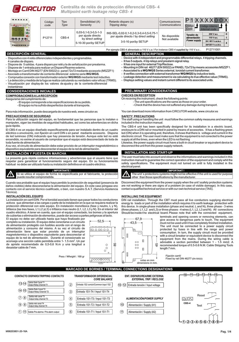
GENERAL DESCRIPTION
- Device with 2 independent, programmable relays, one main relay one prealarm.
- It has 2 outputs. Main trip relay and prealarm signal relay.
- It has 1 potential free input for external trip/reclose.
- Mounting in DIN rail 46277 (EN 50022) or panel 72x72 by means accesories M5ZZF1 .
- Associated to a WGC Series external, toroidal current transformer.
- It verifies connection with external transformer WG/WGS by inductive tests.
- Leakage detection and measurement is via calculating its true effective value (TRMS).
- Displays setting values and instant current different to its associated units.
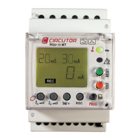
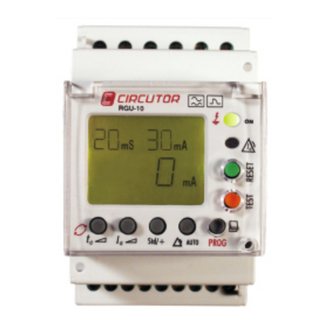
DESCRIPTION LED AND BUTTONS
- Shows equipment status via a display and 2 LED's.
- 5 button equipment setup and setting.
- 2 button equipment TEST and RESET.
INDICATION BY LED AND DISPLAY
- . MAIN TRIP RELAY LED and display signals a
change of status by changing from green to red.
Display event type messages or values.
- . PREALARM SIGNAL. The yellow LED only
comes on when current leakage exceeds the
preset prealarm threshold..
RECLOSING THE EQUIPMENT
- BY TRIP. A manual RESET, or remote or communications ON (where applicable) is required
to return to the equipment's initial status. When the trip is caused by the remote OFF signal,
it can only be re-armed by the remote ON signal.
- BY PREALARM. A manual RESET has to be performed if it is in non-automatic mode to
cancel this status.
( t, I and std/+ )
d d
MAIN RELAY PARAMETER SETTING
- , t.
d
SETTING TRIP DELAY The message and two values appear on the screen after
pressing the button. The lowest value indicates the current set value and the highest is the td
values to be configured which are displayed by pressing The selected value to be saved .
is displayed by showing the message SAVE.
- , I. I.
dd
SENSITIVITY SETTING The same operation as above setting is carried out by pressing
- , std/+. SAFETY SETTING The required safety type through changing the trip contact polarity
is selected by pressing this button. (Std) Standard nothing appears on the display and (+)
Positive, the symbol appears .
( t, I,std/+ and Auto)
d d
PREALARM RELAY SETTING PARAMETERS
A short press on PROG enters the prealarm channel activating the Alarm message on the
display.
- , t.
d
DELAY SETTING . Select the time delay for giving the prealarm signal
- , I. S
d
SENSITIVITY SETTING elect the equipment's prealarm threshold. Selected sensitivity
stated as % in the main channel (OFF-50-60-70-80-MAIN).
- , std/+. S .POLARITY SETTING elect the prealarm output signal polarity
- , Auto. ASETTING OF RESET OF PREALARM ctivating , the equipment automatically
resets the prealarm when the leakage current drops below the preset alarm threshold.
SETUP SETTINGS
A long press on PROG activates the setting menu . Using the PROG and buttons
in this operating mode moves and changes the preset equipment values in the different
setting submenus.
PROG
REC
PROG
+
With the button the submenus are browsed PROG
and with the button the values to be selected
are displayed.
Press PROG to enter the value. The equipment
configures the value by displaying on “SAVE” por
the display and then exits Setting Mode.
If the keypad remains inactive for a certain time,
the equipment automatically exits Setting Mode
and displays without changing the setting “EXIT” .
Mensaje en el display
Bouton
0 ..
.. 99
2.4
4.8
9.6
19.2
38.4
57.6
115.0
0
EN
OD
Bouton PROG
PÉRIPHÉRIQUES
BAUDS
PARIDAD
COM
FREC
LIM
50 Hz
60 Hz
10 s, 30 A
1 s, 3 A
Bouton
Button
0 ..
.. 99
2.4
4.8
9.6
19.2
38.4
57.6
115.0
0
EN
OD
PROG Button
PERIPHERICS
BAUDS
PARITY
COM
FREC
LIM
50 Hz
60 Hz
10 s, 30 A
1 s, 3 A
Button
RS-485
- LED / VERTE : appareil allumé GREEN LED: Equipment on
- LED / ROUGE : déclenchement en raison d'une fuite RED LED: Leakage trip
- LED / JAUNE : Pré-alarme YELLOW LED: Prealarm
- / BOUTON RESET RESET BUTTON
- / BOUTON TEST TEST BUTTON
Cause déclenchement Message à l'écran
Test
Signal distant ON/OFF
Courant de fuite
TESt
EXT
Valeur instantanée
Autres MESSAGES de l'écran
SAVE
EXIT
OVR
ERRt Mauvaise connexion avec
le toroïdal
Validation paramètres
Quitte le mode programmation
Lecture de la valeur hors échelle
Cause of trip
Message display
Test
Remote signal ON/OFF
Current leakage
TESt
EXT
instant value
Other display MESSAGES
SAVE
EXIT
OVR
ERRt
Enters setting values
Exits setting mode
Current leakage reading off scale
Poor toroidal connection
- / SETUP ROTATIONROTATION MENU SETÜP
- / RÉGLAGE DÉLAI DELAY SETTING
- / RÉGLAGE SÉCURITÉ SAFETY SETTING
- / RÉGLAGE SENSIBILITÉ SENSITIVITY SETTING
- - / RÉGLAGE RESET PRÉ-ALARME RESET PREALARM
/ SÉLECTION VALEURS EN PROGRAMMATION VALUES SELECTION SETTING
- / PROGRAMMATION PAR SETUP SETTING BY SETUP PROGRAMMING
- / PROGRAMMATION PRÉ-ALARME SETTING BY PREALARM PROGRAMMING
AUTO
Id
COMM
M98202601-22-20A
Relais de protection différentielle électronique RGU-10C
RGU-10C Electronic Earth-leakage Protection Relay
CONTACTS DECLÉNCHEMENT
/ TRIPPING CONTACTS
SORTIE NA / OUTPUT NO
SORTIE NC / OUTPUT NC
SORTIE COMMUNE / COMMON OUTPUT
13
14
15
CONTACTS PRÉALARME
/ PREALARM CONTACTS
SORTIE COMMUNE / COMMON OUTPUT
SORTIE NC / OUTPUT NC
SORTIE NA / OUTPUT NO
4
5
6
TRANSFORMATEUR DIFFÉRENTIEL
/ CORE BALANCE
ENTRÉE 1S2 / INPUT 1S2
ENTRÉE 1S1 / INPUT 1S1
8
9
ENTRÉE DÉCLENCHEMENT/
RÉARMEMENT EXTERNE
EXTERNAL TRIP/RECLOSE ENTRÉE TENSIÓN / INPUT VOLTAGE
12
DIMENSIONS
DIMENSIONS
10
ALIMENTATION / POWER SUPPLY
ALIMENTATION / SUPPLY (A1)
ALIMENTATION / SUPPLY (A2)
11
45
52,5 43,5
85
67,9
FIXATION SUR RAIL DIN 46277 (EN 50022) M98202601-22-20A
Vial Sant Jordi s/n
08232 Viladecavalls (Bacelona) SPAIN
Tel: (+34) 93 745 29 00
Fax: (+34) 93 745 29 14
Tension maximale : 275 V c.a.)
Contacts protégés par varistance:
Charge nominale en CA : 2 500 VA
-Caractéristiques contacts commutés de sortie 13-14-15 et 4-5-6:
Courant nominal/Maximum courant instantané : 6/10 Ac.a.
Tension nominale : 230 V c.a.
Tournevis recommandés : baguette : 0,4 x 2,5 x 80 mm, longueur 160 mm
Longueur de câble à dénuder : 7 mm
Couple de serrage recommandé : 0,5-0,6 N.m
2
Section câble autorisée : 0,127 - 2,082 mm
-Raccordement :
-Température de travail : -10/+50°C
-Tension d'alimentation nominale : 230 ou 110 V c.a. (+/- 20%) 50/60 Hz, 6 VA
-Type de reconnexion : manuelle, par bouton RESET ou coupure d'alimentation.
-Type de relais : électronique, classe A. Filtrage de courant de haute fréquence.
CARACTÉRISTIQUES TÉCHNIQUES
- : -10ºC / 50ºCOperating temperature
- Rated power supply voltage: 230 o 110 Va.c. (+/- 20%) 50/60 Hz, 6 VA
- Reclosing type: Manual via RESET button or by cutting power supply.
- Tipo Relay type: Electronic class A. High frequency current filtering.
TECHNICAL FEATURES
Maximun operating voltage: 275 V a.c.
- Features varistors
Contacts protected by varistors
AC: 2,500 V·ARated load in
: 230 V a.c.Rated voltage
: 6/10 A a.c.Rated current/Maximum instant current
- 13-14-15 and 4-5-6Switch Output contact features
2
0,127 - 2,082 mmPermissible cable section:
- :Connections
Recommended tightening torque: 0.5-0.6 Nm
Length of cable to strip: 7 mm
Recommended screwdrivers length : Bar 0.4 x 2.5 x 80 mm, 160 mm.
- Trip/reclose input features external 1-2
Input using Optocoupler
Maximum voltage: 230 V a.c.; 0,7 W
Tension maximale : 230 V c.a.; 0,7 W
--Caractéristiques entrée de déclenchement /réarmement externe 1-2
Entrée optocouplée
Courant maximal d'ouverture (voir graphique joint)
Pouvoir de coupure pour charges CC :
Durée de vie utile électrique pour charges CA :
N° de cycles (voir graphique joint)
Electrical useful life for AC loads o. of cycles. : N
(See graph)
Maximun DC Load Breaking Capacity:
Maximum opening current. (See graph)
NL1 L2 L3
UTILISATION
1S1
1S2
USE
Type WG
1S11S2
ON / OFF externe
External ON/OFF
Déclenchement par BOBINE D'ÉMISSION
- Réarmement manuel
Trip by SHUNT COIL.
- Manual reclose.
8 9
1 2 4 56
10
11
13 14 15
Reset
Test
NL1 L2 L3
1S1
1S2
Type WG
1S11S2
ON / OFF externe
External ON/OFF
Déclenchement par BOBINE D'ÉMISSION
- Réarmement automatique
par coupure d'alimentation
Trip by SHUNT COIL.
- Automatic reclose by power
supply out.
Reset
Test
UTILISATION
USE
NL1 L2 L3
1S1
1S2
Type WG
1S11S2
ON / OFF externe
External ON/OFF
Déclenchement par BOBINE
À MINIMUM DE TENSION
- Réarmement manuel
Trip by UNDERVOLTAGE COIL.
- Manual reclose.
Reset
Test
Reset exterior
External reset
UTILISATION
USE
ALIMENTATION C.A. / SUPPLY A.C.
1 2 4 56 8 9 1 2 4 56 8 9
10
11
13 14 15 10
11
13 14 15
SCHÉMAS DE RACCORDEMENT RGU-10 + WGC / CONNECTION DIAGRAM RGU-10 + WGC
MARCAGE DES BORNES
CONNECTIONS DESIGNATIONS
- 1053 certificat UL, IEC 60755, IEC 60947-2 Annexe M
SÉCURITÉ - UL 1053 certification, IEC 60755, IEC 60947-2 Annex M
SAFETY
Note: Circutor guarantees that the RGU-10C device complies with a response time
of less than 30 ms to 5In, and in combination with the selected cutting element must
guarantee a total cut-off time of less than 40 ms to comply with the IEC 60947-2-M
standard.
AUTO RÉGLAGE RESET PRÉALARME
SETTING RESET PREALARM
0,03-0,1-0,3-0,5-1-3-5-10-30 A
0,02-0,1-0,2-0,3-0,4-0,75-1-3-5-10 s
Id
M98202601-22-20A
Vial Sant Jordi s/n
08232 Viladecavalls (Bacelona) SPAIN
Tel: (+34) 93 745 29 00
Fax: (+34) 93 745 29 14
GREEN LED: Equipment ON
RED LED: Leakage trip
SETUP SETTINGS
- Communications (RGU-10C)
- Frecuency 50/60 Hz
- Range values current / time delay.
PREALARM SETTINGS
- Current adjustment (%IDN).
- Delay time
Relais de protection différentielle électronique RGU-10C
RGU-10C Electronic Earth-leakage Protection Relay
COMM
COMM
COMM
COMUNICATIONS
- RGU-10C Un ou plusieurs peuvent être raccordées à un ordinateur ou un PLC par raccordement
série RS-485 La communication est effectuée par un protocole MODBUS RTU. Bits, 8. Stop, 1..
-Les communications avec l'appareil sont affichées à l'écran par le symbole COM
COMM
0000h N de périphérique / Peripherical Number 1 - 99 -
0001h Vitesse des communications / Communications Bauds Rate 2.400-4.800-9.600-19.200-38.400-57.600-115.200 Bauds / Bauds
0002h Parité / Parity None - Odd - Even -
0003h Fréquence de travail / working freqüency 50 - 60 Hz
0004h Courant de déclenchement / Rated residual current, IDN 0,03-0,1-0,3-0,5-1-3-5-10-30 A
0005h Réglage du délai / Tripping Delay setting INS-SEL-0,02-0,1-0,2-0,3-0,4-0,5-0,75-1-3-5-10 s
0006h Polarité relais sortie / Relay output polarity Estandar - Positive(+) -
0007h Courant de déclenchement / Rated tripping current OFF - 50 - 60 - 70 - 8- MAIN %
0008h Réglage du délai / Tripping Delay setting INS-SEL-0,02-0,1-0,2-0,3-0,4-0,5-0,75-1-3-5-10 s
0009h Polarité relais sortie / Relay output polarity Estandard - Positive(+) -
000Ah Type de reconnexion / reclosing type Manuel - REC(automatic) -
000Bh Nº série (HI) / Serial number (HI) 18ADh - 188Ch -
000Ch Nº série (LO) / Serial number (LO) 0000h - FFFFh -
000Dh Version appareil / Equipment version 1 - 99 -
0014h Etat relais / Relays state Off - On (principal) - On (Préalarme/prealarm) -
0015h Valeur efficace courant de fuite / TRMS leakage current value 0 - 65.000 mA
0016h Valeur efficace courant déclenchement / TRMS tripping current value 0 - 65.000 mA
0019h Déclenchement et Reset Externe / External Trip and Reset 0000h - Reset / FFFFh -Test -
001Ah Activer enregistrement configuration / Enable configuration save 0000h -(Activer/enable) / FFFFh -(Enregistrer/save) -
Adresse Description Valeurs Unites Lecture & Ecriture
Addres Description Values Units Read & Write
R/W
R/W
R/W
R/W
R/W
R/W
R/W
R/W
R/W
R/W
R/W
R
R
R
R
R
R
W
W
COMMUNICATIONS
- One or more RGU-10C can be connected to computer or PLC by means RS485 connection.
- The communication is through protocol MODBUS RTU. Data Bits, 8. Stop,1.
- The communications with the equipment are signalized in display by the symbol
COMM
Relais principal
Main Relay
Relais pr alarmeé
Pre-alarm Relay
RGU-10C a une connexion de sortie Rs485 pour les comminications serie.
RGU-10C has a RS-485 series communications output.
A1
A2
RS-232
75
23
5
2
7
2
51
CONVERTISSEUR / INTELIGENT CONVERTER
RS-232 / RS-485
RS-485
Id
AUTO
10
11
12 13 14 15
123 4 56789
5
1
2
A(+)
B(-)
S(GND)
CONNEXION POUR COMUNICATIONS / COMMUNICATIONS CONNECTION
PC
CVMk
LED VERTE : appareil allumé
LED ROUGE: déclenchement
pour fuite
LED JAUNE: Préalarme
YELLOW LED: Prealarm
BOUTON RESET
BUTTON RESET
BOUTON TEST
BUTTON TEST
RÉGLAGE DÉLAI/DELAY SETTING
ROTATION MENU SETUP
ROTATIONAL BUTTON SETUP
Courbe Inverse INS-SEL
RÉGLAGE SENSIBILITÉ/ SENSIVITY SETTING
POLARITÉ CONTACTS
CONTACTS POLARITIES
TEMPS DE RÉGLAGE, td
DELAY TIME
COURANT DE RÉGLAGE , IDN
TRIPPING CURRENT TRESHOLD
VALEUR INSTANTANÉE DE FUITE
INSTANT LEAKAGE CURRENT VALUE
PROGRAMMATIÓN PAR SETUP
- Communications (RGU-10C)
- Fréquence 50/60 Hz
- Échelle valeurs courant et temps
PROGRAMMATION préalarme
- Courant (%IDN) / temps
M98202601-22-20A
Vial Sant Jordi s/n
08232 Viladecavalls (Bacelona) SPAIN
Tel: (+34) 93 745 29 00
Fax: (+34) 93 745 29 14
mS mA
mA
PROG
mS mA
mA
PROG
mS mA
mA
PROG
mS mA
mA
PROG
mS mA
mA
PROG
mS mA
mA
PROG
mS mA
mA
PROG
mS mA
mA
PROG
mS mA
mA
PROG
mS mA
mA
PROG
mSmA
mA
PROG
mSmA
mA
PROG
mS mA
mA
PROG
mS mA
mA
PROG
td
td
td
td
PROG
PROG
PROG
PROG
PROG PROG
PROG PROG
PROG
PROG
td
td
td
td
td
td
td
td
td
PROG
mAmA
Relais de protection différentielle électronique RGU-10C
RGU-10C Electronic Earth-leakage Protection Relay
MENU SETUP / SETUP MENU
SAUVER LES MODIFICATIONS
SAVE CHANGES
SORTIR SETUP
EXIT SETUP

Other manuals for RGU-10C

4

This manual suits for next models

1

Other Circutor Relay manuals

Circutor RGU-10 MT User manual

Circutor

Circutor RGU-10 MT User manual

Circutor RGU-10 RAL User manual

Circutor

Circutor RGU-10 RAL User manual

Circutor CBS-4C-NC User manual

Circutor

Circutor CBS-4C-NC User manual

Circutor RGU-10C User manual

Circutor

Circutor RGU-10C User manual

Circutor CBS-4 Series User manual

Circutor

Circutor CBS-4 Series User manual

Circutor RGU-2 User manual

Circutor

Circutor RGU-2 User manual

Circutor RGU-10C User manual

Circutor

Circutor RGU-10C User manual

Circutor WRU-10 MT User manual

Circutor

Circutor WRU-10 MT User manual

Circutor P24457 User manual

Circutor

Circutor P24457 User manual

Circutor RGU-10 MT User manual

Circutor

Circutor RGU-10 MT User manual

Circutor RGU-10C User manual

Circutor

Circutor RGU-10C User manual

Circutor WRU-10 User manual

Circutor

Circutor WRU-10 User manual

Circutor WRU-10 User manual

Circutor

Circutor WRU-10 User manual

Circutor P11941 User manual

Circutor

Circutor P11941 User manual

Circutor RGU-10 User manual

Circutor

Circutor RGU-10 User manual

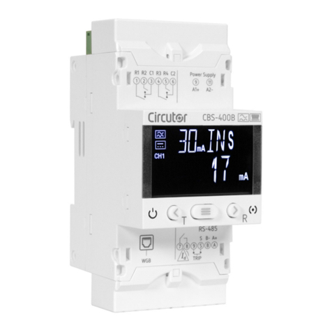
Circutor CBS-400B User manual

Circutor

Circutor CBS-400B User manual

Circutor RGU-10C User manual

Circutor

Circutor RGU-10C User manual

Circutor CBS-4 Series User manual

Circutor

Circutor CBS-4 Series User manual

Circutor CBS-4C User manual

Circutor

Circutor CBS-4C User manual

Circutor CBS-4 Series User manual

Circutor

Circutor CBS-4 Series User manual

Circutor RGU-10A User manual
Circutor

Circutor RGU-10A User manual
Circutor RGU-10 MT User manual

Circutor

Circutor RGU-10 MT User manual

Circutor Master-Slave User manual

Circutor

Circutor Master-Slave User manual

Circutor RGU-10 User manual

Circutor

Circutor RGU-10 User manual

Popular Relay manuals by other brands

KUSSMAUL 091-63-UV instruction manual

KUSSMAUL

KUSSMAUL 091-63-UV instruction manual

Moeller EMR4-A400-1 installation instructions

Moeller

Moeller EMR4-A400-1 installation instructions

Zander Aachen SR3D User information

Zander Aachen

Zander Aachen SR3D User information

GE RPM11A instructions

GE

GE RPM11A instructions

Veris Industries Hawkeye 906 installation guide

Veris Industries

Veris Industries Hawkeye 906 installation guide

GE ML Series 350 Communications manual

GE

GE ML Series 350 Communications manual

Dawnco series 3000 instruction manual

Dawnco

Dawnco series 3000 instruction manual

ABB CM Series Operating and installation instructions

ABB

ABB CM Series Operating and installation instructions

Mobatime NPR Mounting and instruction manual

Mobatime

Mobatime NPR Mounting and instruction manual

Savant CLI-REL1AUX1 Quick reference guide

Savant

Savant CLI-REL1AUX1 Quick reference guide

Eaton MPCV Series Instruction booklet

Eaton

Eaton MPCV Series Instruction booklet

Omega SOLID STATE RELAYS SBG22445 instruction sheet

Omega

Omega SOLID STATE RELAYS SBG22445 instruction sheet

CD Automation REVEX 2PH RX2 280 Series user manual

CD Automation

CD Automation REVEX 2PH RX2 280 Series user manual

Siemens 7SG11 Argus Technical manual

Siemens

Siemens 7SG11 Argus Technical manual

Pilz S3UM operating instructions

Pilz

Pilz S3UM operating instructions

F&F BIS-410-24V manual

F&F

F&F BIS-410-24V manual

Touch-plate ZoneZ Universal quick start guide

Touch-plate

Touch-plate ZoneZ Universal quick start guide

Contrel ELR-3B quick start guide

Contrel

Contrel ELR-3B quick start guide

manuals.online logo
manuals.online logoBrands
  • About & Mission
  • Contact us
  • Privacy Policy
  • Terms and Conditions

Copyright 2025 Manuals.Online. All Rights Reserved.