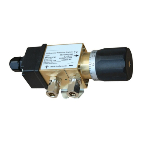
FISCHER DS31 User manual

d e v e l o p i n g s o l u t i o n s
*09005344* BA_EN_DS31 Rev.A 08/12
*09005344*
Table of Contents
1Safety Instructions
2Intended Applications
3Product Description and Functions
4Installation
5Commissioning
6Maintenance
7Transport
8Service
9Accessories
10 Disposal
11 Specifications
12 Ordering Code
13 Dimensions
14 CE-Certificate
1 Safety Instructions
1.1 General information
This operating manual contains detailed
information about the installation, opera-
tion and maintenance of the instrument.
This information must be observed and
read by the installer, operator and other skilled per-
sonnel prior to any installation and commissioning
of the instrument.
This operating manual forms part of the product and
must be kept in the immediate vicinity of the instru-
ment for easy access by the responsible personnel
at any time.
The following chapters, especially the instructions
on installation, commissioning and maintenance
contain important safety information, the non-
compliance of which may result in hazards to per-
sons, animals, environment and objects.
1.1 Personnel qualification
Only personnel trained in the installation, commis-
sioning and operation of this product may install
and operate the same.
Skilled personnel are persons who are able to judge
delegated work and possible hazards based on
their technical education, proficiency and experi-
ences, particularly due to their knowledge about the
applicable norms.
1.2 Risks of non-compliance with safety
instructions
Non-compliance with these safety instructions, in-
appropriate use of this product, and/or operation of
this product outside the limits specified for any of its
technical parameters, may result in harm to per-
sons, the environment or the system in which it is
installed.
The producer is not liable for any claims for damag-
es in such circumstances.
1.3 Safety instructions for operators
Safety instructions for the proper use of this product
must be followed. This information must be availa-
ble at all times to personnel responsible for installa-
tion, operation, maintenance and inspection of this
product.
Adequate steps must be taken to prevent the occur-
rence of hazardous conditions that can be caused
by electric energy and the convertible energy of the
process media and/or improper connection of the
instrument. Detailed information can be found in the
relevant national and/or international rules and reg-
ulations.
In Germany DIN EN, UVV apply, for industry-
specific applications regulations of DVGW, Ex, GL,
as well as the rules of the local authorities (EVUs in
Germany).
Instruction Manual
DS31
Differential Pressure Switch

1.4 Forbidden modifications
Modification or other technical alteration of the de-
vice by the customer is not permissible. This also
applies for the use of spare parts. Any eventual
modifications/ variations will be carried out solely by
Fischer Mess- und Regeltechnik GmbH.
1.5 Impermissible operational modes
The operational dependability of the device is guar-
anteed only if it is used as intended. The device
version must be adapted to the medium used in the
system. The limiting values stated in the technical
data must not be exceeded.
1.6 Safety Considerations during Installa-
tion and Maintenance
The safety instructions stated in this manual, exist-
ing national regulations on accident prevention and
the internal rules and procedures on working, oper-
ation and safety of the operator are to be observed.
It is the responsibility of the operator to ensure that
only authorised and skilled technical personnel car-
ry out any required maintenance, inspection and in-
stallation works.
1.7 Explanation of symbols
WARNING!
... indicates a possible hazardous sit-
uation the non-observance of which
might result in hazards to humans, an-
imals, environment and objects.
2 Intended Applications
Differential pressure switch for positive / negative
gauge pressure or differential pressure of neutral
media such as industrial water, water for heating
systems, neutral gases and oils. The product must
be used only for applications and under conditions
specified by Fischer Mess- und Regeltechnik
GmbH.
3 Product Description and Functions
3.1 Block Schematic Diagram
3.2 Principles of Operation
This pressure switch is based on a rugged and un-
complicated diaphragm movement. It is suitable for
monitoring positive / negative gauge and differential
pressure. The operating principle of the system is
identical in all three cases. The monitored pressure
or differential pressure creates an unbalanced force
on the diaphragm. This force moves the diaphragm
system against the force of the range selector
springs. A tappet, which is mounted on the dia-
phragm, actuates the microswitch.
The setpoint can be adjusted by a scaled hand-
wheel.
4 Installation
4.1 Process Connections
•By authorized personnel only.
•For suitable mechanical fittings only.
•Ensure that the process equipment and pres-
sure lines are at atmospheric pressure before
making pressure connections to the instrument.
•The instrument should be provided with suitable
protection against pressure surges (e.g., snub-
ber or pulsation damper).
•Ensure that the mechanical configuration and
materials of construction of the instrument are
compatible with the process media.
•Ensure that process pressure is always less
than the specified safe pressure rating.
4.2 Electrical Connections
•By authorized personnel only.
•Electrical connections must conform to relevant
international, national and local regulations and
norms relating to electrical and instrumentation
installations.
•Switch off electrical power to the plant before
attempting electrical installation work of any
kind.
•Make electrical connections to the instrument
through a suitable fuse.
•Depending on your order the device is supplied
with Normally Open (NO) or Normally Closed
(NC) contact. Standard: NO contact
NO contact
Operation with
NO contact
(Standard wiring mode)

5 Commissioning
•Power supply and signal cabling to the instru-
ment must be correctly selected to meet opera-
tional requirements, and installed in a way that
does not cause physical stress to the instru-
ment.
•Pressure connections must be ventilated to
avoid measuring failure. If used with water pro-
tect instrument against freezing.
•Prior to commissioning pressure connections
must be checked for leaks.
5.1 Pressure Connections
The instruments pressure ports are marked by (+)
and (-) symbols. The pressure applications need to
be installed according to the label.
•Differential pressure measurement:
+ Higher pressure
- Lower pressure
•Pressure measurement:
+ Pressure port
•Negative pressure measurement:
- Negative pressure port
5.2 Shock Pressure Damping
Pulsating pressure on the plant may lead to me-
chanical wear and disturbances in functional capa-
bility. To avoid this we recommend installing ab-
sorbers into the pressure lines, e.g.: Capillary coil
MZ401 M.
5.3 Switching Point Adjustment
6 Maintenance
The instrument is inherently maintenance-free.
However, to ensure reliable operation and maxim-
ize the operating life of the instrument, it is recom-
mended that the instrument, its external electrical
and process connections, and external connected
devices be regularly inspected, e.g.:
•Check the switching operation in connection to
follow-up components.
•Check all pressure connections for leak-
tightness.
•Check the electrical connection (screw termi-
nals).
Inspection and test schedules depend on operating
and site conditions. The operating manuals of other
equipment to which the instrument is connected
must be read thoroughly to ensure that all of them
work correctly when connected together.
7 Transport
The product must be protected against shock and
vibration during transport. It must therefore be
properly packed, preferably in the original factory
packaging, whenever it is to be transported.
8 Service
Any defective devices or devices with missing parts
should be returned to Fischer Mess- und Regel-
technik GmbH. For quick service contact our ser-
vice department.
Remaining medium in and on dismantled
measuring instruments may cause dan-
ger to persons, environment and equip-
ment. Take reasonable precautions!
Clean the instrument thoroughly if necessary.
9 Accessories
Not available.
10 Disposal
Protect your environment!
Use the product in accordance with rele-
vant regulations. Please be aware of en-
vironmental consequences of disposal at
the end of the product's life, and take
care accordingly.
adjustment knob
arrow marker
scale

11 Specifications
Measuring range
0..0.6 bar up to 0..6 bar
Max. static operating pressure
16 bar (safe against positive and negative pressure)
Permissible ambient temperature
+80°C
Permissible medium temperature
+80°C
Pressurechamber
Brass
Diaphragm
NBR or Viton®, depending on application
Pressure connections
G 1/8 female, cutting ring fitting for 6/8mm tube
Mounting
base for wall mounting
Switching point
10..100 % of range, continuously adjustable
Contact type
Microswitch, hysteresis approx. 2%
Electrical connection
numbered cable, prewired
Contact rating of microswitch
U max 250 V AC; I max 3 A; P max 500 VA
U = max 30 V DC; Imax 0.4 A; P max 10 W
12 Ordering Code
Differential Pressure Switch
DS31
Measuring Ranges
0 ... 0.6 bar..................................................................>
0
1
0 ... 1.0 bar..................................................................>
0
2
0 ... 1.6 bar..................................................................>
0
3
0 ... 2.5 bar..................................................................>
0
4
0 ... 4.0 bar..................................................................>
0
5
0 ... 6.0 bar..................................................................>
0
6
Nominal Pressure
16 bar......................................................................................>
F
Measuring System
Pressure chamber, diaphragm, gaskets: Brass/NBR ..................... >
M
Pressure chamber, diaphragm, gaskets: Brass/Viton .................... >
N
Pressure Connection
G 1/8 female.........................................................................................>
0
0
Cutting ring fitting in steel for 6 mm tube...............................................>
2
0
Cutting ring fitting in brass for 6 mm tube..............................................>
2
8
Cutting ring fitting in brass for 8 mm tube..............................................>
2
9
Switch
1 adjustable microswitch...................................................................................>
A
Electrical Connection*
1m numbered cable, prewired ................................................................................>
1
2.5m numbered cable, prewired ............................................................................. >
2
5m numbered cable, prewired ................................................................................>
5
*Please state switching function with your ordering: NO or NC.

13 Dimensions
Screwed cable gland
M16x1,5

14 CE-Certificate


Technische Änderungen vorbehalten • Subject to change without notice • Changements techniques sous réserve
Fischer Mess- und Regeltechnik GmbH • Bielefelder Str. 37a • D-32107 Bad Salzuflen • Tel. +49 5222 9740 • Fax +49 5222 7170 •
eMail: [email protected] • www.fischermesstechnik.de
Other manuals for DS31
1
Table of contents
Other FISCHER Switch manuals

FISCHER
FISCHER DE45 series Instruction Manual

FISCHER
FISCHER ME50 R Series User manual

FISCHER
FISCHER DS31 User manual

FISCHER
FISCHER DS13 User manual

FISCHER
FISCHER DS 11 User manual

FISCHER
FISCHER DS34 User manual

FISCHER
FISCHER DS 11 User manual

FISCHER
FISCHER DE45 series User manual

FISCHER
FISCHER DS 11 User manual