FISCHER DS 11 User manual

d e v e l o p i n g s o l u t i o n s
*09005104* BA_EN_DS11 Rev.E 11/19
*09005104*
Contents
1Safety guidelines
2Application purpose
3Product and functional description
4Installation and assembly
5Commissioning
6Maintenance and Repeat Tests
7Transport
8Service
9Accessories
10 Waste Disposal
11 Technical data
12 Dimensional drawings
13 Order Codes
14 Manufacturer's Declarations and Certificates
1 Safety guidelines
1.1 General
This operating manual contains instruc-
tions fundamental to the installation,
operation and maintenance of the de-
vice that must be observed uncondi-
tionally. It must be read by the fitter, the operator
and the responsible technical personnel before in-
stallation and commissioning of the device.
This operating manual is an integral part of the
product and therefore needs to be kept close to the
instrument in a place that is accessible at all times
to the responsible personnel.
The following sections, in particular instructions
about the assembly, commissioning and mainte-
nance, contain important information, non-
observance of which could pose a threat to hu-
mans, animals, the environment and property.
1.2 Personnel Qualification
The device may only be installed and commis-
sioned by specialized personnel familiar with the in-
stallation, commissioning and operation of this
product.
Specialized personnel are persons who can assess
the work they have been assigned and recognize
potential dangers by virtue of their specialized train-
ing, their skills and experience and their knowledge
of the pertinent standards.
1.3 Risks due to Non-Observance of Safe-
ty Instructions
Non-observance of these safety instructions, the in-
tended use of the device or the limit values given in
the technical specifications can be hazardous or
cause harm to persons, the environment or the
plant itself.
The supplier of the equipment will not be liable for
damage claims if this should happen.
1.4 Safety Instructions for the Operating
Company and the Operator
The safety instructions governing correct operation
of the instrument must be observed. The operating
company must make them available to the installa-
tion, maintenance, inspection and operating per-
sonnel.
Dangers arising from electrical components, energy
discharged by the medium, escaping medium and
incorrect installation of the device must be eliminat-
ed. See the information in the applicable national
and international regulations.
1.5 Unauthorized Modification
Modifications of or other technical alterations to the
instrument by the customer are not permitted. This
also applies to replacement parts. Only
the manufacturer is authorized to make
any modifications or changes.
User Manual
DS11
Differential pressure switch

2 | 16 Page
1.6 Inadmissible Modes of Operation
The operational safety of this instrument can only
be guaranteed if it is used as intended. The instru-
ment model must be suitable for the medium used
in the system. The limit values given in the technical
data may not be exceeded.
1.7 Safe working practices for mainte-
nance and installation work
The safety instructions given in this operating man-
ual, any nationally applicable regulations on acci-
dent prevention and any of the operating company's
internal work, operating and safety guidelines must
be observed.
The operating company is responsible for ensuring
that all required maintenance, inspection and instal-
lation work is carried out by qualified specialized
personnel.
1.8 Pictogram explanation
WARNING!
… indicates a potentially dangerous
situation, non-observance of which
could endanger persons, animals, the
environment or objects.
INFORMATION!
… highlights important information ef-
ficient and smooth operation.
TIP!
… indicates recommendations that are
not specifically necessary in certain
situations but which could be useful.
2 Application purpose
The DS 11 is a combined display and switching de-
vice for differential pressure, over-pressure and un-
der-pressure. This series is ideally suited for vari-
ous measuring tasks in industrial applications or the
sanitary field.
Typical applications are measuring differential pres-
sure between the supply and return in heating sys-
tems and monitoring filters and pumps. Pressure
chamber and measuring diaphragms are available
in various materials. This allows the devices to be
adapted to the various requirements.
3 Product and functional description
3.1 Function diagram
Item
Description
1
Pressure chamber
2
Motion train
3
Tappet
4
Micro-switch
5
Switch point setting
6
Measuring diaphragm
7
Measuring springs
3.2 Design and mode of operation
A robust and durable membrane measuring instru-
ment is used as a measuring system, which is suit-
able for overpressure and underpressure meas-
urements. The units use the same measuring prin-
ciple for all three measuring applications.
In the rest position, the spring forces on both sides
of the membrane are balanced out. Due to the
pressure or underpressure to be measured, a sin-
gle-sided force is created on the membrane which
shifts the membrane system against the measure-
ment range springs up to equalization of the spring
forces. In case of overload, the membrane supports
against the metallic support surfaces.
A centrally positioned tappet transfers the move-
ment of the membrane system on the motion train
and operating elements of the micro-switches.
4 Installation and assembly
The standard device is designed for wall mounting.
The device can be mounted to even walls using the
assembly foot that is cast to the middle of the de-
vice. It is also possible to fit the device in switch
cabinets using the switch panel installation kit
DZ11.
It is calibrated ex-works for vertical installation; this
is the only allowed installation position.
To ensure safety during installation and mainte-
nance, we recommend installing a suitable shut-off

3 | 16 Page
valve on the system (see accessories section). This
means that
the device can be depressurized or taken out of
operation
the device can be disconnected from the power
supply within the applicable system for repairs
or inspections.
•a function test of the device can be performed
on-site.
4.1 Process connection
•By authorized and qualified specialized person-
nel only.
•Only for the designated mechanical process
connection (for the model, see the order code
on the device type plate)
•The pipes need to be depressurized when the
device is being connected.
•Appropriate steps must be taken to protect the
device from pressure surges.
•Check the suitability of the device for the media
to be measured.
•Maximum pressures must be observed.
•Check that the pressure connections do not
leak before commissioning.
4.1.1 Pressure sensing lines
Remark
Commissioning and repeat tests can be
carried out more efficiently by using a
suitable shut-off device.
The pressure connections are marked with (+) and
(-) symbols on the device. For differential pressure
measurements, the higher pressure is connected to
the (+) side and the lower pressure to the (-) side of
the device. When measuring the pressure, only the
(+) connection is used; the (-) connection is used to
measure under-pressure.
The pressure sensing lines need to be kept as short
as possible and installed without sharp bends to
avoid interfering delay times.
The pressure sensing lines must be installed on a
gradient so that no air pockets e.g. for liquid meas-
urements or water pockets e.g. for gas measure-
ments can be created. If the required inclination is
not reached, water or air filters must be installed at
suitable places.
If liquid measuring media are used the pressure
connection lines must be deaerated, as liquid col-
umns of different heights in the pipes can cause
measuring errors. The instrument must be protect-
ed against frost if water is used as a medium.
4.1.2 Pressure surge absorption
Pulsating pressure on the system side can lead to
wear and functional problems. To safeguard this,
we recommend installing absorption elements in the
pressure pipe line.
Fluid media
In the operational status, the reactor pins need to
be set so that the measurement display follows the
pressure changes with a delay.
Gaseous media
4.2 Electrical connections
•By authorized and qualified specialized person-
nel only.
Settable reactor pins below the clos-
ing cap
G¼
Capillary throttle coil MZ 401

4 | 16 Page
•The electrical connection of the device shall be
performed according to relevant VDE and local
electricity board regulations.
•Disconnect the system from the mains before
connecting the device.
•Add a fuse adapted to the energy requirements.
4.2.1 Cable socket and plug connection
Cable socket
Plug connection
4.2.2 Numbered cables
For models with numbered cables, the cable num-
bers correspond with the presented terminal num-
bers.
5 Commissioning
All electrical supply, operating and measuring lines,
and the pressure connections must have been cor-
rectly installed before commissioning. All supply
lines are arranged so that there are no mechanical
forces acting on the device.
Check that the pressure connections do not leak
before commissioning.
5.1 Control Elements
5.2 Zero point correction
Depressurize the measuring chamber.
Remove the hood
Set the measurement value pointer to the zero-
point scale using the zero point correction
screw.
Re-mount the hood.
5.3 Switch point setting
Remove the plug in the hood.
The required switch points can be set guide
value scales according to the markings by us-
ing a screwdriver. The achievable setting accu-
racy is ± 5 %.
1
Replace the plug after completing the settings.
5.4 Function test
Remove both plugs in the hood for testing.
If the unit has two micro-switches, the stated test
steps must be carried out for both switches.
After the test, the switch points need to be reset
acc. to 5.3.
5.4.1 Checking the switch points when the
system is depressurized.
No measurement is shown and the measurement
display points to zero.
Turn the switch point setting button toward the zero-
point until the micro-switch is activated.
1
More accurate settings can be made either in the factory or on
site using suitable aids (test manometer, ohm meter etc.)
Ground connection
Zero-point correction screw
Switch point setting
switch 1
Switch point setting
switch 2
Switch 1
Switch 2

5 | 16 Page
5.4.2 Testing when the system is operational
A measurement is shown. If despite operational
pressure, no measurement is shown, you can gen-
erate a differential pressure by blocking the differ-
ential pressure lines on one side.
Turn the switch point setting button toward the
measurement until the micro-switch is activated.
6 Maintenance and Repeat Tests
The instrument is maintenance-free.
To ensure reliable operation and a long service life,
we recommend carrying out an annual test. The
purpose of this test is to ensure that it functions cor-
rectly. There are instructions on how to carry out a
function test in the commissioning section.
7 Transport
The measuring device must be protected against
impacts. It should be transported in the original
packaging or a suitable transport container.
8 Service
All defective or faulty devices should be sent direct-
ly to our repair department. Please coordinate all
shipments with our sales department.
Warning
Process media residues in and
on dismantled devices can be a hazard
to people, animals and the environment.
Take adequate preventive measures. If
required, the devices must be cleaned thoroughly.
Return the device in the original packaging or a
suitable transport container.
9 Accessories
•DZ11 Switch panel installation kit Ø 132
•DZ13/14 Blocking and equalization valve
10 Waste Disposal
Incorrect disposal may pose a risk to the environ-
ment.
Please help to protect the environ-
ment by always disposing of the work
pieces and packaging materials in
compliance with the valid national
waste and recycling guidelines or re-
use them.

6 | 16 Page
11 Technical data
General points
Admissible ambient temperature
-10 … +70 °C
Admissible media temperature
-10 … +70 °C
Admissible storage temperature
-15 … +75 °C
Enclosure protection class
IP55 acc. to DIN EN 60529
Weight
1.2 kg (Pressure chamber in aluminium)
3.5 kg (Pressure chamber in stainless steel 1.4305)
Measuring system
Measuring range ≤ 16 bar
Pressure spring measuring diaphragm system made of fabric-reinforced elastomers
Measuring range 0 … 25 bar
Plate spring measuring system, plate spring made of DURATHERM©
Measuring range
0 … 400 mbar to 0 … 25 bar (see order code)
Rated pressure of the
measuring system
25 bar
Max. static operating pressure
depending on measuring range (see order code)
Max. pressure load
on-sided over-pressure-proof up to the rated pressure of the measuring system
resistance to under-pressure on the (+) and (-) side
Measurement accuracy
± 2.5% of the upper range value
Zero-point adjustment
Arranged in the front panel of the scale
Switch contacts
Contact output
1 or 2 micro-switches with 1-pin changeover contact.
Switch point setting
can be set to reference scales from outside
Smallest settable value approx. 5% of the end value of the measuring range.
Switch hysteresis
approx. 2.5% of the upper range value
Load data/contact
AC
DC
Umax
250V
30V
Imax
5A
0.4A
Pmax
250 VA
10 W
Ports
Process connection
Inner thread G 1/4
Connecting shank G¼ DIN EN 837
Cutting ring connections for 6, 8, 10 mm (brass, steel galvanized or stainless steel)
electr. connection
Fixed wire numbered cables
Cable connection socket
7-pole plug connection
Materials
Pressure chamber
Aluminium GkAlSi10(Mg), painted black
Aluminium GkAlSi10(Mg) with HART-COAT©-surface protection
Chromium nickel steel 1.4305
Measuring diaphragm
Measuring diaphragm and sealsmade of NBR or Viton©
Plate spring made of DURATHERM© NiCrCo alloy
Inner parts in contact with
mediums
Stainless steel 1.4310, 1.4305
Hood
Makrolon
Mounting
Installation position
vertical
Wall mounting - three mounting feet
Control panel assembly - control panel installation set DZ11 Ø132mm
Pipe connection, pressure connections acc. to attached symbols
- via screwed-in cutting or clamp screw connections
- via screwed-in connection shanks acc. to DIN EN 837
for nipple connections acc. to DIN 16284
Approvals
type testing according to the regulations of Det Norske Veritas and the Germanischen Lloyd,
test symbol DNV-GL
EAC Declaration of conformity
EN 61508 2001 Functional safety of safety-related electrical/electronic/
programmable electronic systems requirements for SIL2

7 | 16 Page
12 Dimensional drawings
Cutting ring screw connection
DS11 Wall mounting (Standard model)
(all dimensions in mm unless otherwise specified)
M16x1.5
plastic
screw connection
Bolt circle (LK)
EL-connection variants
Process connection variants
M20x1.5 Cable screw connection
Cable connection socket or
7-pin plug connection
SW19
Connection
G¼ inner thread
Connection spigot
G¼ according to DIN EN 837
DZ 13/14 Four spindle equalization and shut-off valve
Mounting the control panel
opened
opened
Measuring
device
Venting
Function diagram
DZ 13/14
Venting (n/a for DZ13)
Cutting ring screw connection
Control panel cut-out
Bolt circle (LK)

8 | 16 Page
13 Order Codes
Differential pressure measuring and switching device
Type DS11
0
0
Measuring range
Max. stat. operating
pressure
0 …400..mbar.....................................................
.. 6 bar..........................>
8
3
0 …0.6..bar........................................................
10 bar..........................>
0
1
0 …1..bar........................................................
16 bar..........................>
0
2
0 …1.6..bar........................................................
25 bar..........................>
0
3
0 …2.5..bar........................................................
25 bar..........................>
0
4
0 …4..bar........................................................
25 bar..........................>
0
5
0 …6..bar........................................................
25 bar..........................>
0
6
0 …10..bar........................................................
25 bar..........................>
0
7
0 …16..bar........................................................
25 bar..........................>
0
8
0 …25..bar........................................................
25 bar..........................>
0
9
- 0.6 …0..bar........................................................
10 bar..........................>
3
0
- 1 …0..bar........................................................
16 bar..........................>
3
1
- 1 …+0.6.bar........................................................
25 bar..........................>
3
2
- 1 …+1.5.bar........................................................
25 bar..........................>
3
3
- 1 …+3..bar........................................................
25 bar..........................>
3
4
- 1 …+5..bar........................................................
25 bar..........................>
3
5
0 …30..psi.........................................................
25 bar..........................>
H
5
Measuring membrane / Seal
NBR NBR.................................................>
N
Viton®Viton®..............................................>
V
DURATHERM®NBR (Mb 0-25 bar)..........................>
D
DURATHERM®Viton®(Mb 0-25 bar)........................>
E
Pressure chamber
Aluminium ...........................................................................................>
A
Aluminium HART COAT®...................................................................>
D
Chromium nickel steel 1.4305..............................................................>
W
Discharge port
Inner thread G 1/4 .......................................................................................>
0
1
Inner thread 1/4 - 18 NPT............................................................................>
0
4
Connection shanks with external thread G 1/4 B, brass...............................>
0
6
Connection shanks with external thread G 1/4 B, Chrome-Nickel-Steel.......>
1
1
Connection shanks with external thread 1/4 - 18 NPT EXT Chrome-Nickel-
Steel............................................................................................................>
1
4
Cutting ring screw connection made of steel for 6 mm pipe .........................>
2
0
Cutting ring screw connection made of steel for 8 mm pipe .........................>
2
1
Cutting ring screw connection made of steel for 10 mm pipe .......................>
2
2
Cutting ring screw connection made of 1.4571 for 6 mm pipe......................>
2
4
Cutting ring screw connection made of 1.4571 for 8 mm pipe......................>
2
5
Cutting ring screw connection made of 1.4571 for 10 mm pipe....................>
2
6
Cutting ring screw connection in brass for 6 mm pipe..................................>
2
8
Cutting ring screw connection in brass for 8 mm pipe..................................>
2
9
Cutting ring screw connection in brass for 10 mm pipe................................>
3
0
Switching Elements
1 adjustable micro-switch ............................................................................................>
A
2 adjustable micro-switches.........................................................................................>
B
Electrical connection
1 metre numbered cable, permanently wired.......................................................................>
1
2.5 metre numbered cable, permanently wired ....................................................................>
2
5 metre numbered cable, permanently wired.......................................................................>
5
Cable connection socket......................................................................................................>
K
Plug connection (7-pin)........................................................................................................>
W
DNV-GL-approved version with 3 m connection cable ........................................................>
Z
SEV-approved version, 2 m connection cable VDE NYSLYO ...........................................>...
U
Casing protection class
IP55.............................................................................................................................................>
0
IP65 (only with cable socket).......................................................................................................>
P
Assembly options
Panel mounting set..............................................................................................................................>
T
Wall mounting......................................................................................................................................>
W

9 | 16 Page
13.1 Accessories
DZ11
Control panel installation set Ø 132, comprising a front ring, distance columns and at-
tachment screws.
DZ13/14
The shutoff and equalization valves DZ13/14 in three and four spindle versions are highly
suitable when mounting differential pressure devices. The following can be used for ex-
ample:
•is a system is to be depressurized or taken out of operation
•for repairs or tests to disconnect differential pressure devices within the affected
systems from the mains supply
The shutoff devices can therefore also be used for function tests on site. In contrast to
DZ13, the DZ14 also has a venting valve to vent the conected pipe system. The shutoff
and venting valves are designed for the rated pressure level PN40. The housing can be
selected in aluminium, brass or chrome-nickel-steel 1.4301. There are various pressure
connections (see order code) available for process-side screw connections.

10 | 16 Page
14 Manufacturer's Declarations and Certificates
14.1 EC Declaration of conformity

11 | 16 Page
14.2 Certificate functional security SIL2

12 | 16 Page

13 | 16 Page
14.3 GL approval

14 | 16 Page

15 | 16 Page

Technische Änderungen vorbehalten • Subject to change without notice • Changements techniques sous réserve
Fischer Mess- und Regeltechnik GmbH • Bielefelder Str. 37a • D-32107 Bad Salzuflen • Tel. +49 5222 9740 • Fax +49 5222 7170
eMail: [email protected] • www.fischermesstechnik.de
14.4 EAC Declaration of conformity
Other manuals for DS 11
2
Table of contents
Other FISCHER Switch manuals

FISCHER
FISCHER DS 11 User manual

FISCHER
FISCHER DE45 series User manual
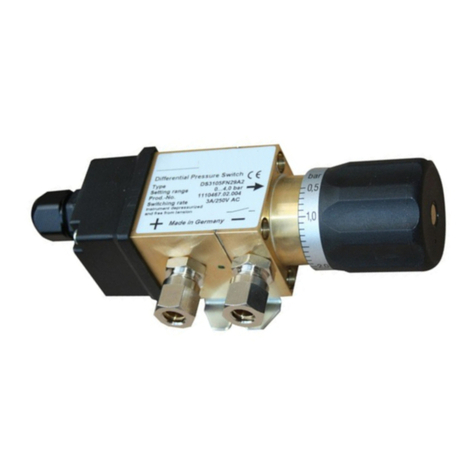
FISCHER
FISCHER DS31 User manual
FISCHER
FISCHER DE45 series Instruction Manual
FISCHER
FISCHER DS 11 User manual
FISCHER
FISCHER DS13 User manual

FISCHER
FISCHER ME50 R Series User manual

FISCHER
FISCHER DS31 User manual

FISCHER
FISCHER DS34 User manual
Popular Switch manuals by other brands
HP
HP A5500 HI Series installation guide
Cisco MERAKI
Cisco MERAKI MS390-24-HW installation guide

ZyXEL Communications
ZyXEL Communications ES-315 quick start guide
Moxa Technologies
Moxa Technologies EtherDevice EDS-G205A-4PoE Quick installation guide
Cypress
Cypress CLUX-41AT Operation manual
Cisco
Cisco MGX 8850 PXM45 Release notes
