Fisher Body FOLDING TOP 1971 User manual
1971
FISHER
BODY
SERVICE
MANUAL
FOLDING
TOP
SUPPLEMENT
"B"
AND "E"
CONVERTIBLE
STYLES
This publication contains
the
essential
removal,
installation,
adjustment
and
maintenance
procedures
for servicing
Folding Tops
on
all U.S.
and
Canadian
built
1971
liB
and
II
E"
Convertible
Fisher Body Styles.
All
information,
illus-
trations,
and
specifications
contained
in
this publication
are
based
on
the
latest
product
information
available
at
the
time
of
publication
approval.
The right
is
reserved
to
make
changes
at
any
time without notice.
©
1970
GENERAL
MOTORS CORPORATION
FISHER
BODY DIVISION
LITHO
IN U.S.A.
PART
NO.
8704198-A
DECEM8ER
1970
FOLDING
TOP
FOLDING
TOP
"8"
AND "E"
STYLES
INDEX
SUBJECT PAGE
Introduction . Removal and Installation 22
Description .
23
23
Folding
Top
Trim
Left
Folding
Top Cover
and
Back Curtain Assembly 3 Removal and Installation
Removal 3 Back Window
Guide
Control Link and Spring 24
24
25
25
25
Back Curtain Assembly
26
26
26
26
27
Folding Top Side
Quarter
Pad Assembly
28
28
30
Removal and Installation 30
30
30
..
32
33
35
Installation
10
Removal
and
Installation
Folding Top Cover (Less Back Curtain)
12
Folding Top Actuator Assembly
Removal
12
Removal
Installation
13
Installation
Removal
15
Actuators
Installation
16
Folding Top Adjustments
Folding Top Silencer Assembly
17
Description
Removal
18
Checking Tension on Stacked Folding Top
Installation
19
Folding Top Stacked Position Tension Adjustment
Removal
19
Adjustment.
Installation 20 Description
Folding Top
Gutter
20 Procedure
Folding
Top
Hardware Components
22
Rails
Front
Roof
Rail Lock
22
Description
Removal and Installation 22 Procedure
Front
Roof Rail Locating Pin
22
Side
Roof
Rail Tension Adjustment
Removal and Installation 22
Front
Roof
Rail Lock Hook Adjustment
Folding Top Electric Motor
and/or
Relay
22
Folding Top
Main
Hinge
"L.ward" Adjustment
15
SUBJECT PAGE
Folding Top Actuator Drive Cable-Right
and/or
Procedure for Synchronizing Folding Top
19
Locating Pin and Side Roof Rail Height
20 Checking Tension
of
(Up
Position) Side
Roof
INTRODUCTION
DESCRIPTION
1971
"B
and
E"
convertible styles feature
an
"inward"
folding top. Service replacement
of
folding top trim
components
is
somewhat different from past models.
Hardware construction and trim material attachment
feature revised design concepts (Figs. 2 and 5). The
convertible top involves a precise adjustment proce-
dure which must be performed as outlined in this
manual. the motor, operates the drive cables. Other
gear
Side
roof
rails are hinged at the front, center
and
rear.
The hinging design enables the side
roof
rails to fold
"inwardly"
when the top
is
lowered (Fig. 2). The
roof
cross bows, and trimstick stack
to
the rear
of
the side
rails. The back window stacks under the
roof
rails and guide control link and spring at each lower corner.
The inward folding top gutter
of
convertible top trim
bows.
The inward folding top stacks
to
a flush position in the
folding .top compartment. The folding top well
is
shorter in length and provides full-width
rear
seat
back comfort and leg room comparable to closed body
styles.
Operation
of
the top
is
controlled by an electric switch.
The top
is
powered by a reversible electric motor
and
two
gear
reduction units. One gear reduction unit, at
reduction units are integral with the top actuator
assemblies at each main hinge. Drive cables supply
power
to
the actuators which, in turn, multiply the
power to operate the top. During top operation, the
solid-tempered glass back window
is
controlled by a
2
FOLDING
TOP
8 10
3
4357
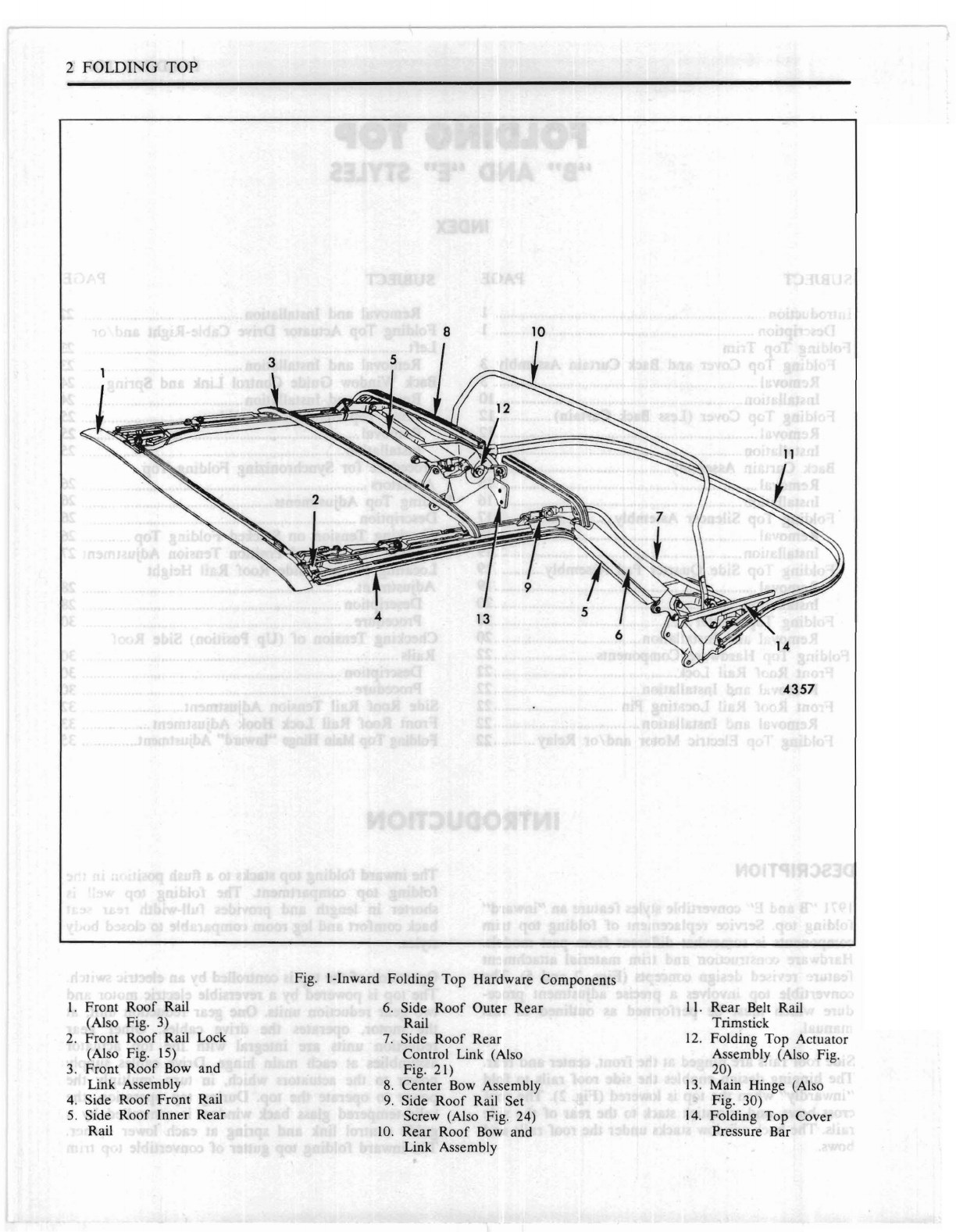
Fig. I-Inward Folding Top Hardware Components
I. Front
Roof
Rail
6.
Side
Roof
Outer Rear
II.
Rear Belt Rail
(Also Fig. 3) Rail Trimstick
2. Front
Roof
Rail Lock
7.
Side
Roof
Rear
12.
Folding
Top
Actuator
(Also Fig. IS) Control Link (Also Assembly (Also Fig.
3.
Front
Roof
Bow and Fig. 21) 20)
Link Assembly
8.
Center
Bow
Assembly
13.
Main Hinge (Also
4.
Side
Roof
Front Rail
9.
Side
Roof
Rail Set Fig. 30)
5.
Side Roof Inner Rear Screw (Also Fig. 24)
14.
Folding
Top
Cover
Rail
10.
Rear Roof
Bow
and Pressure Bar
Link Assembly
FOLDING
TOP
3
construction controls
drainage
of
water
at
the
rear
belt
rail.
The
left side rail folds before the right rail upon
stacking.
The
side rail folding sequence causes the
front
roof
rail to be non- parallel to the ground
during
a
portion
of
top operation. This
is
a normal condition.
IMPORTANT: Before lowering the top, check the
folding top
compartment
inside the
car
and
in the
rear
compartment.
Remove all luggage
and
parcels from
the folding top
compartment
inside the car. Also,
if
necessary, clear away any luggage
or
miscellaneous
parcels in the
rear
compartment
which may have slid
forward into the folding top
compartment
storage
area.
Failure
to do so could result
in
breakage
of
the
back window glass
or
damage
to the folding top
mechanism
during
operation
of
the top.
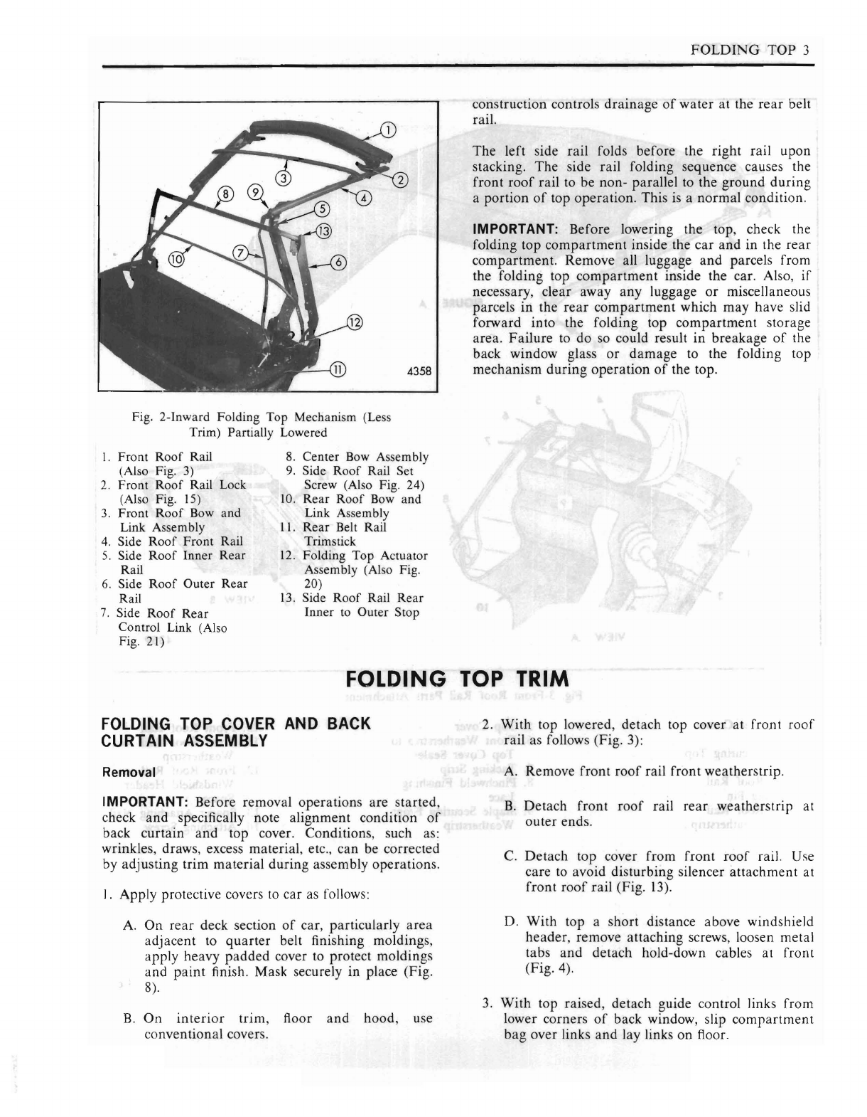
Fig. 2-Inward Folding Top Mechanism (Less
Trim) Partially Lowered
I.
Front
Roof
Rai]
8.
Center
Bow Assembly
(Also Fig. 3)
9.
Side
Roof
Rail Set
2.
Front
Roof
Rail Lock Screw (Also Fig. 24)
(Also Fig. 15)
10.
Rear
Roof
Bow and
3.
Front
Roof
Bow and Link Assembly
Link Assembly
II.
Rear
Belt Rail
4.
Side
Roof
Front Rail Trimstick
5.
Side
Roof
Inner
Rear
12.
Folding
Top
Actuator
Rail Assembly (Also Fig.
6.
Side
Roof
Outer
Rear
20)
Rail
13.
Side
Roof
Rail Rear
7.
Side
Roof
Rear
Inner to Outer Stop
Control Link (Also
Fig. 21)
FOLDING TOP TRIM
FOLDING TOP COVER AND BACK 2.
With
top lowered, detach top cover at front
roof
CURTAIN ASSEMBLY rail as follows (Fig. 3):
Removal A. Remove front
roof
rail front weatherstrip.
IMPORTANT: Before removal operations
are
started,
B.
Detach front
roof
rail
rear
weatherstrip at
check
and
specifically note alignment condition
of
outer ends.
back
curtain
and
top cover. Conditions, such as:
wrinkles, draws, excess material, etc., can
be
corrected
C.
Detach
top cover from front
roof
rail. Use
by adjusting trim material during assembly operations. care to avoid disturbing silencer
attachment
at
front
roof
rail (Fig.
13).
I.
Apply protective covers to car as follows:
D. With top a short distance above windshield
A.
On
rear
deck section
of
car, particularly
area
header, remove attaching screws, loosen metal
adjacent to
quarter
belt finishing moldings, tabs
and
detach hold-down cables at front
apply heavy
padded
cover to protect moldings (Fig. 4).
and
paint
finish. Mask securely in place (Fig.
8).
3.
With
top raised, detach guide control links from
B.
On
interior
trim, floor
and
hood, use lower corners
of
back window, slip
compartment
conventional covers.
bag
over links
and
lay links on floor.
4
FOLDING
TOP
VIEW
A
13
VIEW
B
4359
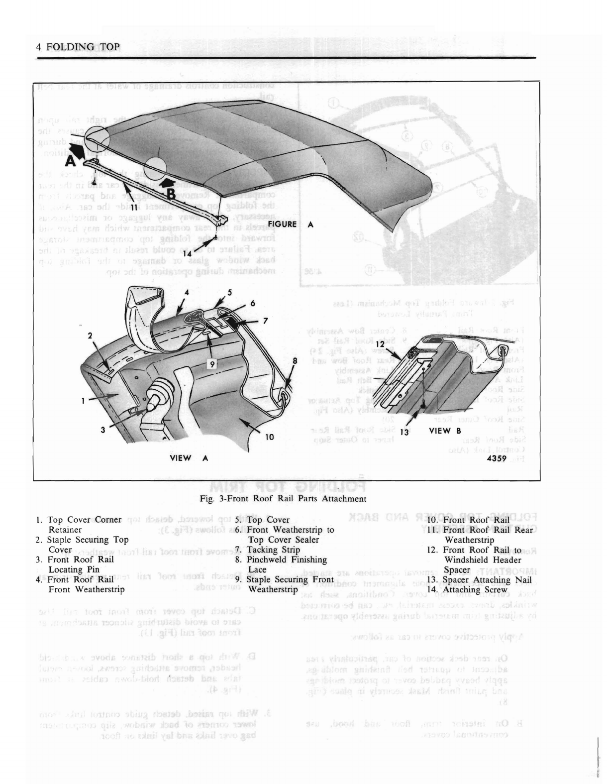
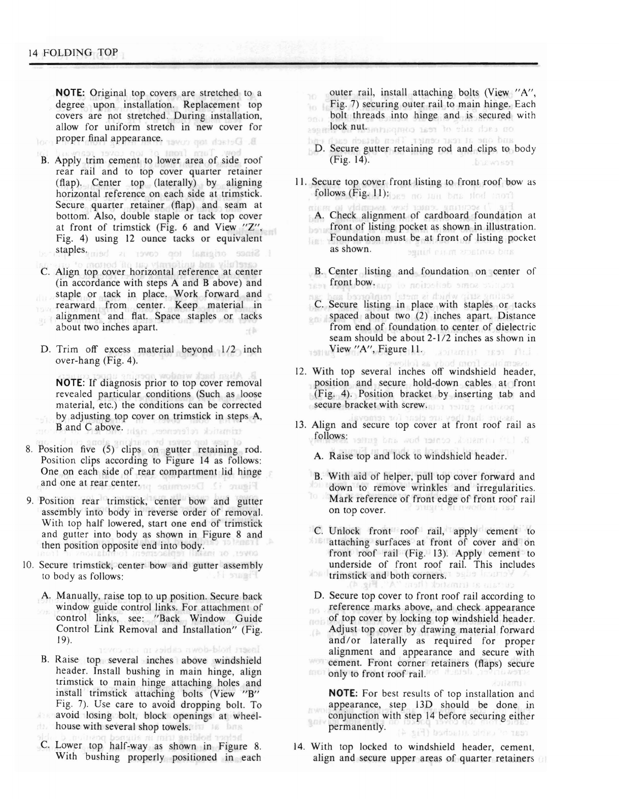
Fig. 3-Front
Roof
Rail Parts
Attachment
I.
Top
Cover
Corner
5.
Top
Cover 10.
Front
Roof
Rail
Retainer
6.
Front
Weatherstrip to
II.
Front
Roof
Rail
Rear
2. Staple Securing
Top
Top
Cover Sealer Weatherstrip
Cover
7. Tacking Strip
12.
Front
Roof
Rail to
3.
Front
Roof
Rail
8.
Pinchweld Finishing Windshield
Header
Locating Pin Lace
Spacer
4.
Front
Roof
Rail
9.
Staple Securing
Front
13.
Spacer
Attaching Nail
Front
Weatherstrip Weatherstrip
14.
Attaching Screw
FOLDING
TOP 5
VIEW
Y
4362
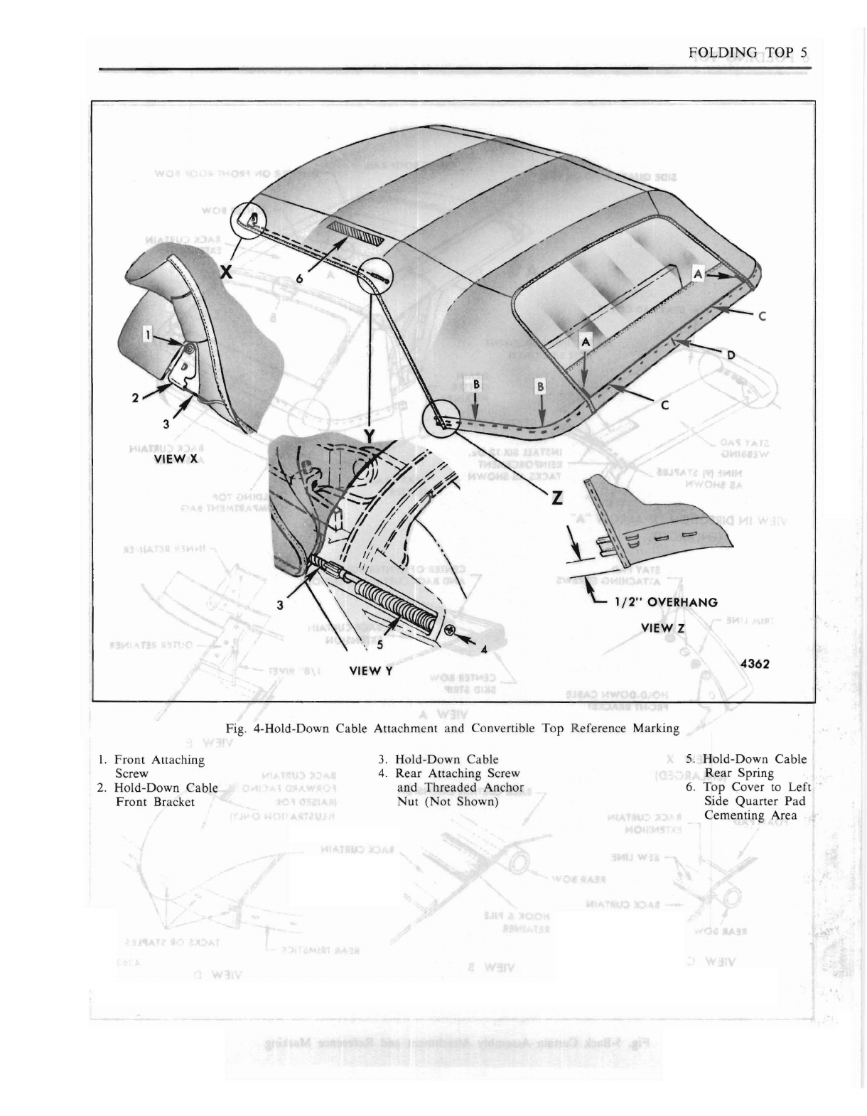
Fig. 4-Hold-Down Cable Attachment and Convertible
Top
Reference Marking
I.
Front
Attaching
3.
Hold-Down Cable
5.
Hold-Down Cable
Screw
4.
Rear
Attaching Screw
Rear
Spring
2.
Hold-Down Cable and
Threaded
Anchor 6.
Top
Cover
to
Left
Front
Bracket
Nut
(Not
Shown) Side
Quarter
Pad
Cementing Area
x
6 FOLDI G TOP
FRONT ROOF RAIL
STAY PAD COVER
BACK CURTAIN
ASSEMBLY
CENTER
BOW
FOLDING TOP
COMPARTMENT BAG
SILENCER
ON
FRONT ROOF
BOW
DRAIN
GUTTER
RETAINeR
CENTER
BOW
INSTALL SIX
12
Oz.
-.....:2'!LJ~-~-
REINFORCEMENT
TACKS AS
SHOWN
SIDE QUARTER IFOAM} PAD
NINE
19)
STAPLES
AS
SHOWN
VIEW
IN
DIRECTION OF ARROW
"A"
(ENLARGED)
VIEW B
STAY
PAD
ATTACHING SCREWS
HOLD.DOWN
CABLE
FRONT
BRACKET
FOAM
PAD BACK CURTAIN
\ rEXTENSION
VIEW X
(ENLARGED)
BACK CURTAIN
--
EXTENSION
CENTER
OF tENTER
BOW
AND
BACK CURTAIN EXTENSION
VIEW A
VIEW E
BACK CURTAIN
'\.
BACK CURTAIN EXTENSION
\
.~/
/4
/",
/
"
••••.•
:.-/
..••/ BACK CURTAIN
-~~/
SEW LINE
REAR
BOW"""'O
o
'''-:''-'
__
BACK CURTAIN
HOOK
&
PILE
REAR
BOW
RETAINER
VIEW C
FORWARD FACING.,
(RAISED
FOR
ILLUSTRATION ONLY]
VIEW D
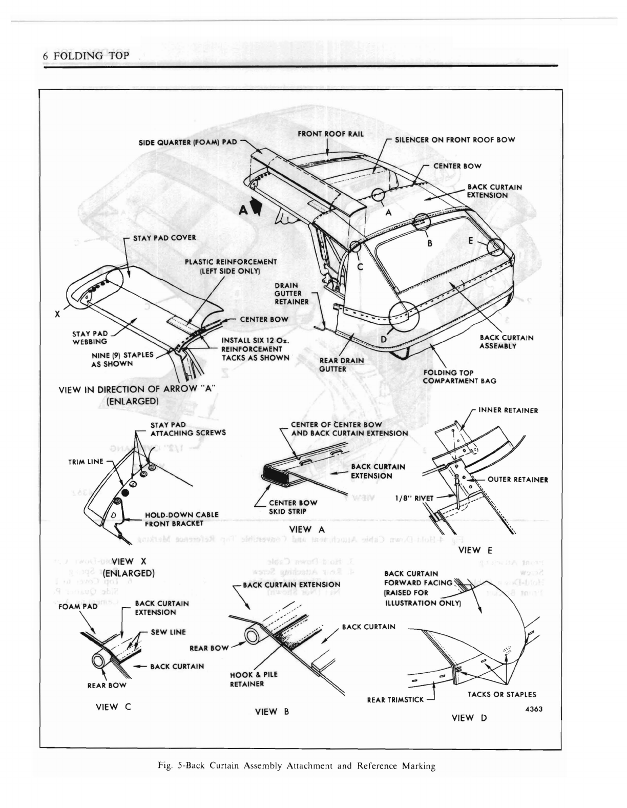
Fig. 5-Bat:k
Curtain
Assembly
Attat:hment
and
Reference
Marking
4363

FOLDING
TOP
7
4364
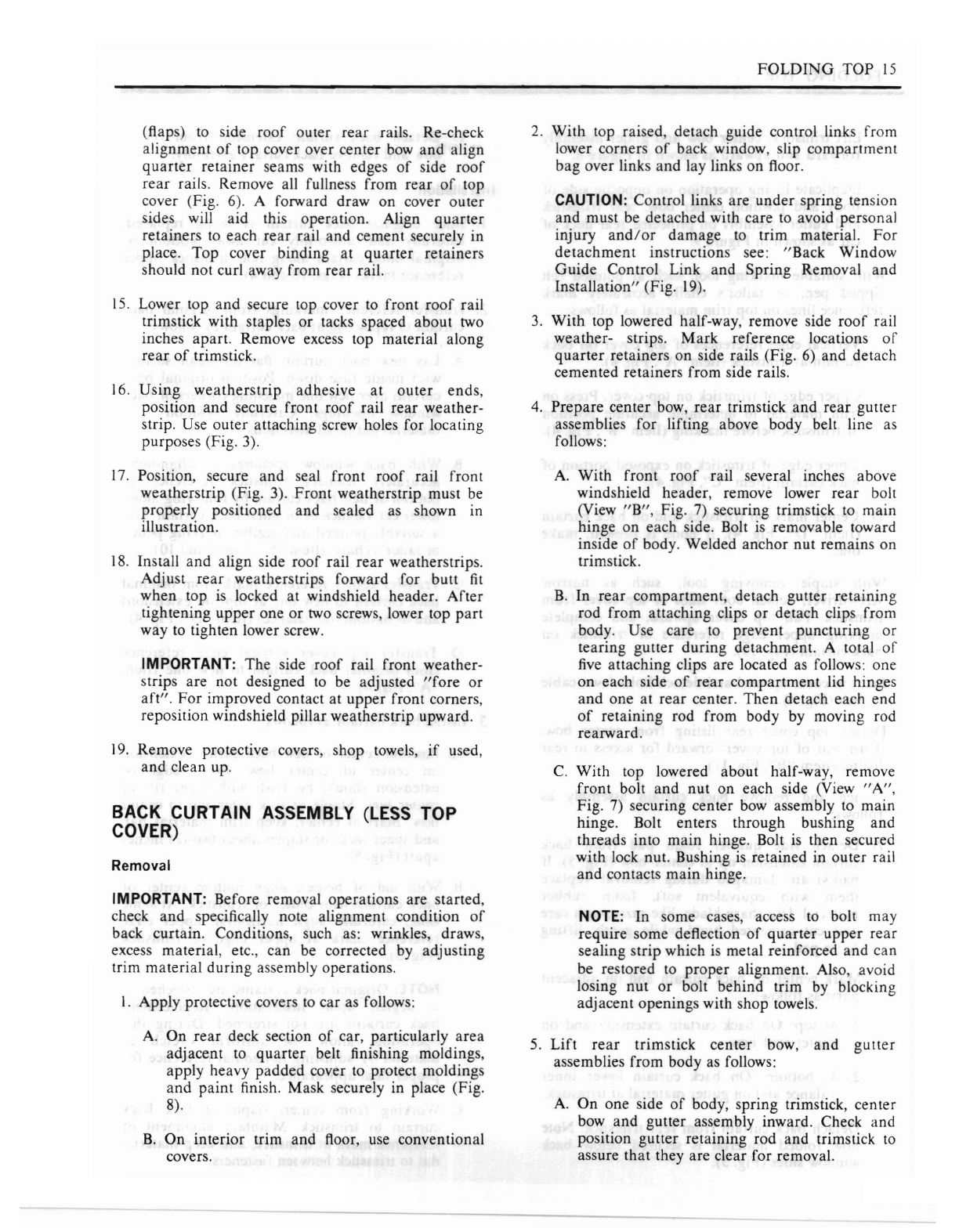
Fig. 6-Side
Roof
Rail
Rear
Weatherstrip and
Quarter
Retainer Attachment
I. Side
Roof
Outer
Rear
Rail
2.
Side
Roof
Inner
Rear
Rail
3.
Top
Cover
Rear
Quarter Retainer (Flap)
4.
Cementing Surfaces for Retainer
5.
Retainer Seam Aligned With Outer
Rear
Rail
6.
Side
Roof
Rail
Rear
Weatherstrip
7.
Attaching Screw
CAUTION: Control links are
under
spring tension
and
must be detached with care to avoid personal
injury
and/or
damage
to trim material.
For
detachment
instructions
see:
"Back
Window
Guide
Control Link
and
Spring
Removal
and
Installation"
(Fig.
19).
4.
With
top lowered half-way, remove side
roof
rail
rear
weatherstrips. Mark reference locations
of
quarter
retainers
on
side rails (Fig. 6)
and
detach
cemented retainers from side rails.
5.
Prepare
center bow,
rear
trimstick
and
rear
gutter
assemblies
for
raising above body belt line as
follows:
A.
With
front
roof
rail several inches above
windshield header, remove lower
rear
bolt
(Item
"B",
Fig. 7) securing trimstick to
main
hinge on each side. Bolt is removable toward
inside
of
body. Welded anchor nut
remains
on
trimstick.
B.
In
rear
compartment,
detach gutter
retaining
rod from attaching clips,
or
detach clips from
body (Fig. 14). Use care to prevent
puncturing
or
tearing gutter during detachment. A total
of
five
attaching
clips are located as follows: one
on
each side
of
rear
compartment
lid hinges
and
one
at
rear
center.
Then
detach each end
of
retaining
rod from body by moving rod
rearward.
C.
With
top lowered about half-way, remove
front bolt
and
nut on eacb side (Item
"A",
Fig. 7) securing center bow assembly
to
main
hinge. Bolt enters through bushing
and
threads into
main
hinge. Bolt
is
then secured
with lock nut. Bushing is retained in outer rail
and
contacts
main
hinge.
NOTE: In some cases, access to bolt
may
require some deflection
of
quarter
upper
rear
sealing strip which is metal reinforced
and
can
be restored to
proper
alignment. Also, avoid
losing nut
or
bolt behind trim by blocking
adjacent openings with shop towels.
6.
Lift
rear
trims
tick,
center
bow
and
gutter
assemblies as follows:
A.
On
one side
of
body, spring trimstick,
center
bow
and
gutter
assembly inward. Check
and
position
gutter
retaing rod
and
trimstick to
assure
that
they are clear for removal.
B.
Lift trimstick, center bow
and
gutter assembly
forward
and
upward as shown in Figure
8.
C.
Duplicate lifting
operation
on
opposite side
of
body,
and
position center bow,
rear
trimstick
and
gutter assembly on protected
rear
deck
of
car
as shown in Figure
9.
7.
With
suitable
marking
tool, such as pointed felt
tipped pen,
or
tailor's chalk, accurately
mark
reference lines
on
top trim material as follows:
A. Vertical edge references
of
top cover
on
back
curtain at trimstick
(Item"
A", Fig. 4).
B.
Upper
edge
of
trimstick
on
top cover. Press on
trim material to determine accurate position
of
trimstick before
marking
(Item
"B",
Fig. 4).
c.
Upper
edge
of
trimstick on exposed portion
of
back
curtain
(Item
"C",
Fig. 4).
D.
Center
mark
on
trimstick
and
on back
curtain
(Item
"0",
Fig. 4).
If
none
is
present, make
one.
8.
With
staple removing tool, such as narrow
screwdriver, detach both sides
of
top cover from
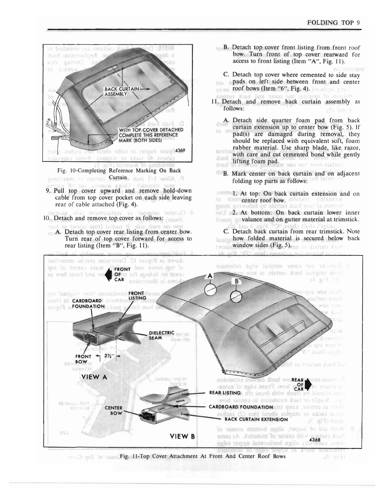
trimstick. Pull top cover upward, and complete
marking
upper
edge reference
of
trimstick on
back curtain (Fig. 10).

8
FOLDING
TOP
8
3
VIEW
"8"
7
4365
VIEW
"A"
Fig. 7-Center Bow Assembly and
Rear
Trimstick Attachment
I.
Attaching Bolt 3. Bushing
6.
Main Hinge
8.
Anchor
Nut
(Part
of
2.
Side
Roof
Outer
Rear
4.
Threaded
Hole in
7.
Rear
Trimstick
(Part
Trimstick)
Rail
(Part
of
Center Main Hinge
of
Center Bow
9.
Center
Bow
Bow Assembly)
5.
Lock
Nut
Assembly)
REAR
TRIMS
TICK
Fig. 8-Lifting
Rear
Trimstick From Body Fig. 9-Rear Trimstick
on
Rear Deck
of
Car
DIELECTRIC
FOLDING
TOP
9
B.
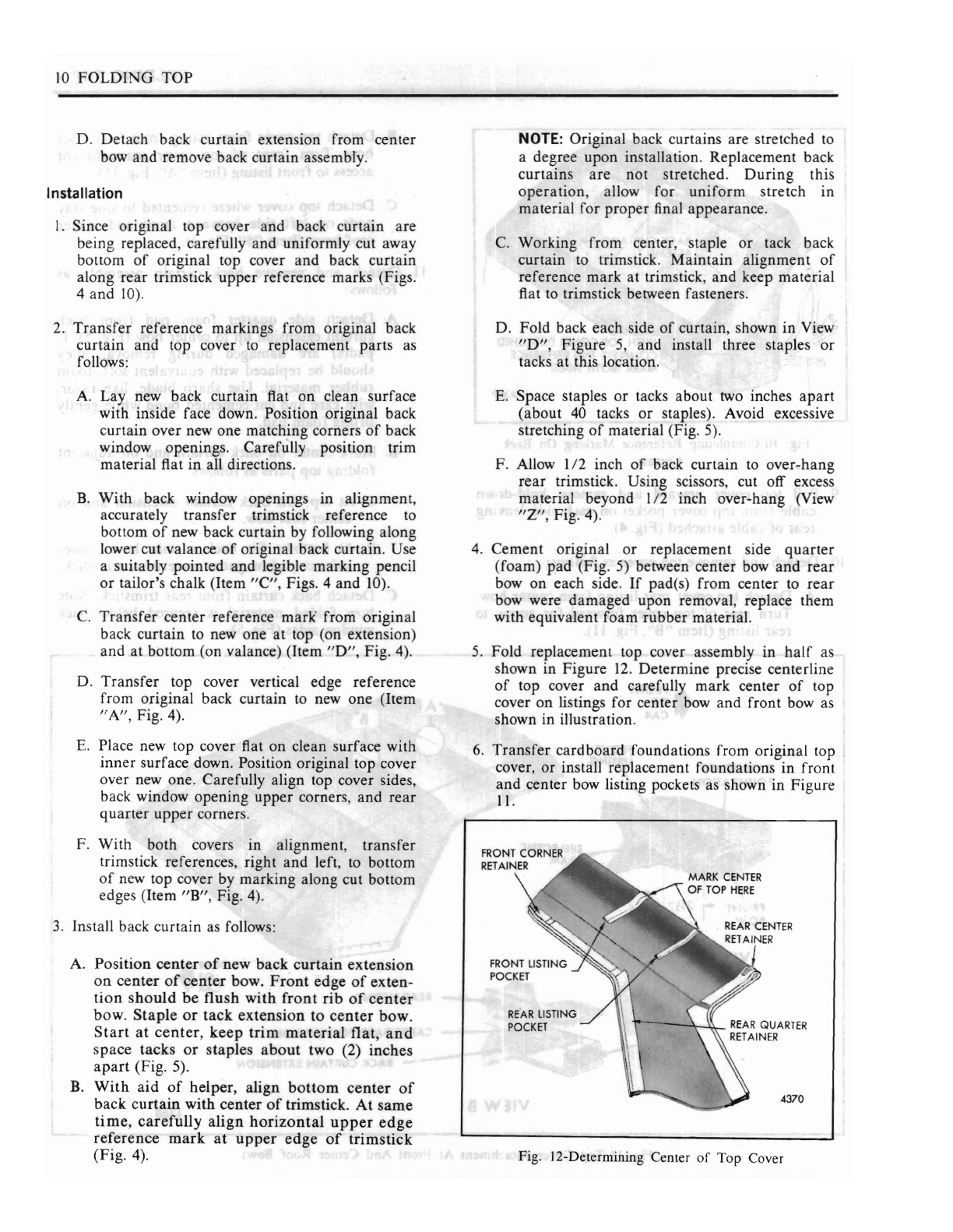
Detach top cover front listing from front
roof
bow.
Turn
front
of
top cover rearward for
access
to
front listing
(Item"
A", Fig.
II).
C.
Detach top cover where cemented
to
side stay
pads
on left side between front and center
roof
bows (Item
"6",
Fig. 4).
II.
Detach and remove back curtain assembly as
follows:
A. Detach side
quarter
foam
pad
from back
curtain extension up
to
center bow (Fig. 5).
If
WITH
TOP
COVER
DETACHED
r---...:>c:""71
COMPLETE
THIS
REFERENCE
pad(s)
are
damaged
during removal, they
MARK
(BOTH
SIDESj
should be replaced with equivalent soft, foam
rubber
material. Use
sharp
blade, like razor,
4369
with care and cut cemented bond while gently
lifting foam pad.
B.
Mark center on back curtain
and
on adjacent
folding top parts
as
follows:
9.
Pull top cover upward and remove hold-down
I.
At top: On back curtain extension
and
on
cable from top cover pocket on each side leaving center
roof
bow.
rear
of
cable attached (Fig. 4).
2.
At bottom: On back curtain lower
inner
10.
Detach and remove top cover
as
follows: valance and on gutter material at trimstick.
A. Detach top cover
rear
listing from center bow.
C.
Detach back curtain from
rear
trimstick. Note
Turn
rear
of
top cover forward for access to how folded material
is
secured below back
rear
listing (Item
"B",
Fig.
II).
window sides (Fig. 5).
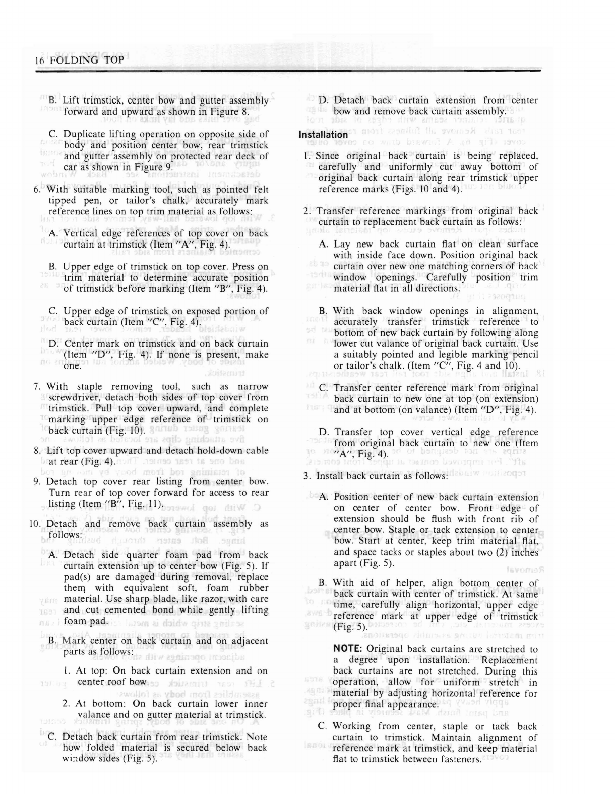
Fig. IO-Completing Reference Marking On Back
Curtain
fRONT
Of
~
CAR
SEAM
fRONT
LISTING
I
fRONT
2Yz";'
!
BOW
VIEW
A
REAR
LISTING
CARDBOARD
fOUNDATION
CENTER$d
BOW
".,
_
- BACK CURTAIN EXTENSION
VIEW
B
REARt
Of
CAR
Fig.
II-Top
Cover
Attachment
At Front And
Center
Roof
Bows
10
FOLDING
TOP
D.
Detach
back
curtain
extension
from
center
bow
and
remove
back
curtain
assembly.
Installation
I.
Since
original
top cover
and
back
curtain
are
being
replaced,
carefully
and
uniformly
cut away
bottom
of
original
top cover
and
back
curtain
along
rear
trimstick
upper
reference
marks
(Figs.
4
and
10).
2.
Transfer
reference
markings
from
original
back
curtain
and
top
cover to
replacement
parts
as
follows:
A.
Lay
new
back
curtain
flat
on
clean
surface
with
inside
face down. Position
original
back
curtain
over
new
one
matching
corners
of
back
window
openings.
Carefully
position
trim
material
flat
in
all directions.
B.
With
back
window
openings
in
alignment,
accurately
transfer
trimstick
reference
to
bottom
of
new
back
curtain
by following
along
lower
cut
valance
of
original
back
curtain.
Use
a
suitably
pointed
and
legible
marking
pencil
or
tailor's
chalk
(Item
"C",
Figs. 4
and
10).
C.
Transfer
center
reference
mark'
from
original
back
curtain
to new
one
at
top (on
extension)
and
at
bottom
(on
valance)
(Item
"0",
Fig. 4).
D.
Transfer
top
cover vertical
edge
reference
from
original
back
curtain
to new
one
(Item
"A",
Fig. 4).
E.
Place new
top
cover flat
on
clean
surface
with
inner
surface
down. Position
original
top
cover
over
new one.
Carefully
align
top cover sides,
back
window
opening
upper
corners,
and
rear
quarter
upper
corners.
F.
With
both
covers
in
alignment,
transfer
trimstick references,
right
and
left, to
bottom
of
new
top
cover
by
marking
along
cut
bottom
edges
(Item
"B",
Fig. 4).
3.
Install back
curtain
as follows:
A.
Position
center
of
new
back
curtain
extension
on
center
of
center
bow.
Front
edge
of
exten-
tion
should
be
flush
with
front
rib
of
center
bow.
Staple
or
tack
extension
to
center
bow.
Start
at
center,
keep
trim
material
flat,
and
space
tacks
or
staples
about
two
(2)
inches
apart
(Fig.
5).
B.
With
aid
of
helper,
align
bottom
center
of
back
curtain
with
center
of
trimstick.
At
same
time,
carefully
align
horizontal
upper
edge
reference
mark
at
upper
edge
of
trimstick
(Fig.
4).
NOTE:
Original
back
curtains
are
stretched
to
a
degree
upon
installation.
Replacement
back
curtains
are
not
stretched.
During
this
operation,
allow
for
uniform
stretch
in
material
for
proper
final
appearance.
C.
Working
from
center,
staple
or
tack back
curtain
to trimstick.
Maintain
alignment
of
reference
mark
at
trimstick,
and
keep
material
flat to trimstick between fasteners.
D.
Fold
back
each
side
of
curtain,
shown
in
View
"0",
Figure
5,
and
install
three
staples
or
tacks
at
this location.
E.
Space
staples
or
tacks
about
two inches
apart
(about
40
tacks
or
staples). Avoid excessive
stretching
of
material
(Fig. 5).
F.
Allow
1/2
inch
of
back
curtain
to
over-hang
rear
trims
tick.
Using
scissors, cut
off
excess
material
beyond
112
inch
over-hang
(View
"Z",
Fig. 4).
4.
Cement
original
or
replacement
side
quarter
(foam)
pad
(Fig. 5) between
center
bow
and
rear
bow
on
each
side.
If
pad(s)
from
center
to
rear
bow
were
damaged
upon
removal, replace
them
with
equivalent
foam
rubber
material.
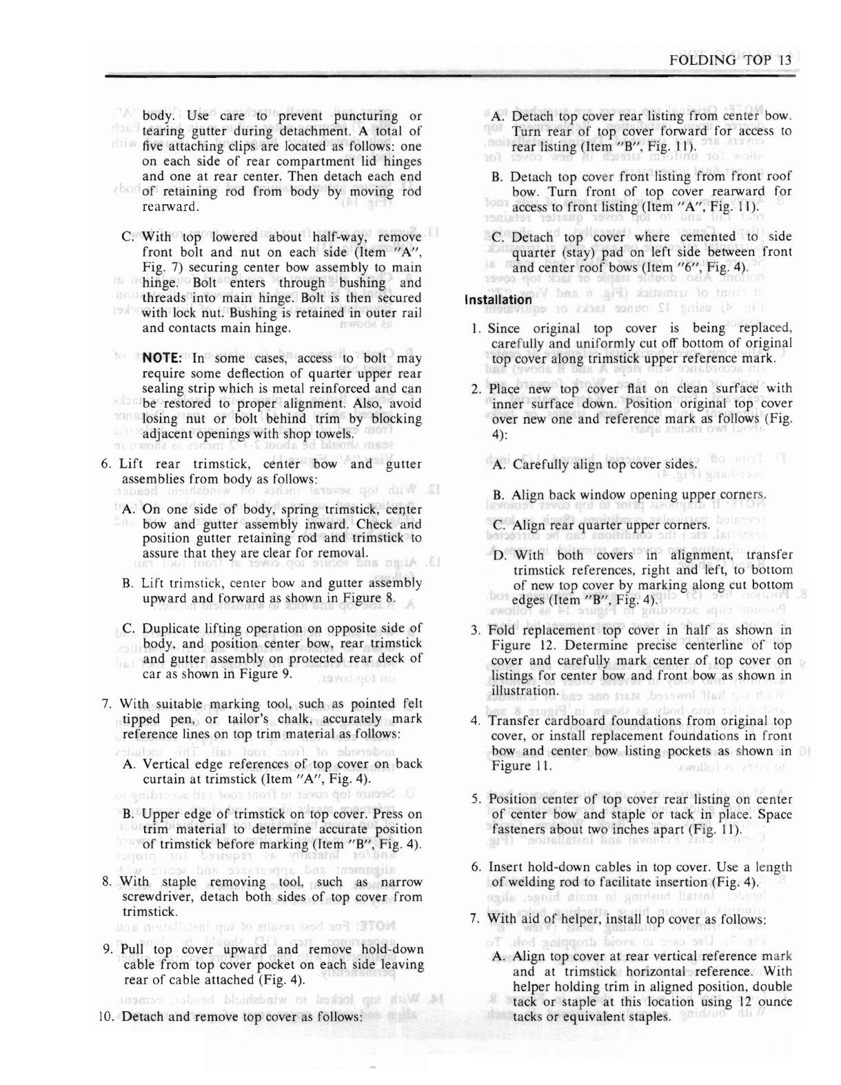
5.
Fold
replacement
top cover
assembly
in
half
as
shown
in
Figure
12.
Determine
precise
centerline
of
top
cover
and
carefully
mark
center
of
top
cover
on
listings
for
center
bow
and
front
bow as
shown
in
illustration.
6.
Transfer
cardboard
foundations
from
original
top
cover,
or
install
replacement
foundations
in
front
and
center
bow listing pockets as shown
in
Figure
II.
REAR
LISTING
POCKET
4370
Fig. 12-Determining Center
of
Top
Cover
FOLDING
TOP
II
7.
Position
center
of
top cover
rear
listing
on
center
bow
and
staple
or
tack in place. Space fasteners
about
two (2) inches
apart
(Fig.
II).
8.
Insert hold-down cables in top cover. Use a length
of
welding
rod to facilitate insertion (Fig. 4).
9.
With
aid
of
helper, install top cover as follows:
A. Align top cover
at
rear
vertical reference
mark
and
at trimstick horizontal reference (Items
"A"
and
"C",
Fig. 4).
With
helper holding
trim
in
aligned position, double tack
or
staple
at
this location using
12
ounce tacks
or
equivalent staples.
NOTE:
Original top covers are stretched to a
degree
upon
installation. Replacement top
covers
are
not stretched.
During
installation,
allow for uniform stretch in new cover for
proper
final appearance.
B.
Apply trim cement to lower
area
of
side
roof
rear
rail
and
to top cover
quarter
retainer
(flap).
Center
top (laterally) by aligning
horizontal reference on each side at trimstick.
Secure
quarter
retainer
(flap)
at
bottom. Also,
double staple
or
tack top cover at
front
of
trimstick (Fig. 6
and
View
"Z",
Fig. 4) using
12
ounce tacks
or
equivalent staples.
C. Align top cover horizontal refere..
ce
at center
(in accordance with steps A
and
B above)
and
staple
or
tack in place. Work forward
and
rearward from center. Keep material in
alignment
and
flat. Avoid stretching. Space
staples
or
tacks about two (2) inches apart.
D.
Trim
off excess material beyond
1/2
inch
over-hang
(Fig. 4).
NOTE:
If
diagnosis prior to top cover removal
revealed particular conditions (Such as: Loose
material, etc.) the conditions can be corrected
by adjusting top cover on trimstick in steps A,
Band
C above.
10.
Position
five
(5) clips on gutter
retammg
rod.
Position clips according to Figure
14
as follows:
One
on each side
of
rear
compartment
lid hinge
and
one at
rear
center.
II.
Position
rear
trimstick, center bow
and
gutter
assembly into body in reverse
order
of
removal.
With
top half-lowered, start one end
of
trimstick
and
gutter into body as shown in Figure
8,
then
position opposite
end
into body.
12.
Secure trimstick, center bow
and
gutter assembly
to body as follows:
A. Raise top to up position. Secure back window
guide control links.
For
attachement
of
control
links see: "Back Window
Guide
Control Link
Removal
and
Installation" (Fig.
19).
B.
Raise top several inches above windshield
header. Install bushing in
main
hinge, align
trimstick to
main
hinge attaching holes
and
install trimstick attaching bolts (View
"B",
Fig. 7). Use care
to
avoid
dropping
bolt. To
avoid losing bolt, block openings at wheel-
house with several shop towels.
C.
Lower top half-way as shown in
Figure
8.
With
bushing properly positioned in each
outer
rail, install attaching bolts (View
"A",
Fig. 7) securing outer rail to
main
hinge. Each
bolt threads into hinge
and
is secured with
lock nut.
D. Secure
rear
gutter retaining rod
and
clips to
body as shown in Figure
14.
13.
Secure top cover front listing to front
roof
bow as
follows (Fig.
II):
A. Check alignment
of
cardboard
foundation at
front listing pocket as shown in illustration.
Foundation
must be at front
of
listing pocket
as shown.
B.
Center
listing
and
foundation on
center
of
front
bow.
C. Secure listing in place with staples
or
tacks
spaced
about
two (2) inches apart. Distance
from
end
of
foundation to
center
of
dielectric
seam should be about
2-1/2
inches as shown in
View
"A",
Figure
II.
14.
With
top several inches off windshield header,
position
and
secure hold-down cables at front
(Fig. 4). Position bracket by inserting
tab
and
secure bracket with screw, then secure metal tab.
15.
Align
and
secure top cover at front
roof
rail as
follows:
A. Raise top
and
lock
to
windshield header.
B.
With aid
of
helper, pull top cover forward
and
down to remove wrinkles
and
irregularities.
Mark
reference
of
front edge
of
front
roof
rail
on
top cover.
C. Unlock front
roof
rail, apply
cement
to
attaching
surfaces
at
front
of
cover
and
on
front
roof
rail (Fig.
13).
Apply cement to
underside
of
front
roof
rail. This includes
tacking strip
and
both corners.

12
FOLDING
TOP
D. Secure top cover
to
front
roof
rail according
to
reference marks above, and check appearance
of
top cover by locking top to windshield
header. Adjust top cover by drawing material
forward
and/or
laterally as required for
proper
alignment
and
appearance, and secure
with cement.
Front
corner retainers (flaps)
secure only
to
front roof rail.
NOTE:
For
best results
of
top installation and
appearance, step 15D should be done in
conjunction with step
16
before securing either
permanently.
16.
With
top locked
to
windshield header, cement,
align
and
secure upper areas
of
quarter
retainers
(flaps)
to
side roof outer
rear
rails. Re-check
alignment
of
top cover over center bow.and align
quarter
retainer
seams with edges
of
side
roof
rear
rails. Remove all fullness from
rear
of
top
cover (Fig. 6). A forward draw on cover outer
sides will aid this operation. Align
quarter
retainers
to
each
rear
rail and cement securely in
place. Top cover binding at
quarter
retainers
should not curl away from
rear
rail.
17.
Lower top
and
secure top cover
to
front
roof
rail
trimstick with staples or tacks spaced about two
inches apart. Remove excess top material along
rear
of
trimstick.
18.
Using
weatherstrip
adhesive
at
outer
ends,
position and secure
rear
weatherstrip on front
roof
rail. Use outer attaching screw holes for
locating purposes (Fig. 3).
19.
Position, secure
and
seal front roof rail front
weatherstrip (Fig. 3).
Front
weatherstrip must be
properly positioned and sealed as shown in
illustration.
20. Install and align side roof rail
rear
weatherstrips.
Adjust
rear
weatherstrips forward for butt
fit
when
top
is
locked at windshield header. After
tightening
upper
two screws, lower top
part
way
to
tighten lower screw.
IMPORTANT: Side
roof
rail front weatherstrips
are not designed
to
be adjusted
"fore
or
aft".
For
improved contact
at
upper front corners, reposi-
tion windshield pillar weatherstrips upward.
21. Remove all protective covers
and
clean up.
FOLDING TOP COVER
(LESS
BACK
CURTAIN)
Removal
IMPORTANT: Before removal operations are started,
check
and
specifically note alignment
of
top cover.
Conditions, such as: wrinkles, draws, excess material,
etc.,
can
be corrected by adjusting trim material
during
assembly operations.
I.
Apply protective covers
to
car as follows:
A. On
rear
deck section
of
car, particularly
area
adjacent to
quarter
belt finishing moldings,
apply heavy
padded
cover
to
protect moldings
and
paint
finish. Mask securely in place (Fig.
8).
B.
On
interior
trim, floor
and
hood, use
conventional covers.
2.
With top lowered, detach top cover at front
roof
rail as follows (Fig. 3):
A. Remove front
roof
rail front weatherstrip.
B.
Detach front
roof
rail
rear
weatherstrip at
outer ends.
C.
Detach top cover from front roof rail. Use
care
to
avoid disturbing silencer attachment at
front
roof
rail (Fig.
13).
D. With top a short distance above windshield
header, remove attaching screws,
unbend
metal tabs,
and
detach hold-down cables
at
front (Fig. 4).
3. With top raised, detach guide control links from
lower corners
of
back window, slip
compartment
bag over links and lay links on floor.
CAUTION: Control links are
under
spring tension
and
must be detached with care to avoid personal
injury
and/or
damage
to
trim material.
For
detachment
instructions see:
"Back
Window
Guide
Control Link and
Spring
Removal and
Installation" (Fig.
19).
4.
With top lowered half-way, remove side
roof
rail
rear
weatherstrips. Mark reference locations
of
quarter
retainers on side rails (Fig. 6) and detach
cemented retainers from side rails.
5.
Detach center bow,
rear
trimstick
and
rear
gutter
assemblies for raising above body belt line as
follows:
A. With front
roof
rail several inches above
windshield header, remove lower
rear
bolt
(Item
"B",
Fig.
7)
securing trimstick to
main
hinge on each side. Bolt
is
removable toward
inside
of
body. Welded anchor nut remains on
trimstick.
B.
In
rear
compartment, detach gutter
retammg
rod from attaching clips
or
detach clips from
FOLDING
TOP
13
body. Use care
to
prevent puncturing or
tearing gutter during detachment. A total
of
five
attaching clips are located as follows: one
on each side
of
rear
compartment lid hinges
and
one at
rear
center. Then detach each end
of
retaining
rod from body by moving rod
rearward.
C.
With top lowered about half-way, remove
front bolt
and
nut on each side (Item
"A",
Fig.
7)
securing center bow assembly to main
hinge. Bolt enters through bushing and
threads into main hinge. Bolt
is
then secured
with lock nut. Bushing
is
retained in outer rail
and
contacts main hinge.
NOTE:
In some cases, access
to
bolt may
require some deflection
of
quarter
upper
rear
sealing strip which
is
metal reinforced
and
can
be restored
to
proper
alignment. Also, avoid
losing nut
or
bolt behind trim by blocking
adjacent openings with shop towels.
6.
Lift
rear
trimstick,
center
bow
and
gutter
assemblies from body
as
follows:
A.
On
one side
of
body, spring trimstick,
ceI').ter
bow and gutter assembly inward. Check
and
position gutter retaining rod and trimstick
to
assure
that
they are clear for removal.
B.
Lift trimstick, center
bow
and
gutter assembly
upward and forward
as
shown in Figure
8.
C.
Duplicate lifting operation on opposite side
of
body, and position center bow, rear trimstick
and gutter assembly on protected rear deck
of
car as shown in Figure
9.
7.
With suitable marking tool, such as pointed felt
tipped pen,
or
tailor's chalk, accurately mark
reference lines on top trim material as follows:
A. Vertical edge references
of
top cover on back
curtain
at
trimstick
(Item"
A", Fig. 4).
B.
Upper
edge
of
trimstick on top cover. Press on
trim material
to
determine accurate position
of
trimstick before marking (Item "B", Fig. 4).
8.
With staple removing tool, such as narrow
screwdriver, detach both sides
of
top cover from
trimstick.
9.
Pull top cover upward and remove hold-down
cable from top cover pocket on each side leaving
rear
of
cable attached (Fig. 4).
10.
Detach and remove top cover
as
follows:
A. Detach top cover rear listing from center bow.
Turn
rear
of
top cover forward for access
to
rear
listing (Item
"B",
Fig.
II).
B.
Detach top cover front listing from front
roof
bow.
Turn
front
of
top cover rearward for
access
to
front listing (Item
"A",
Fig.
II).
C.
Detach top cover where cemented to side
quarter
(stay) pad on left side between front
and center
roof
bows (Item
"6",
Fig. 4).
Installation
I. Since original top cover
is
being replaced,
carefully and uniformly cut off bottom
of
original
top cover along trimstick upper reference mark.
2.
Place new top cover flat on clean surface with
inner
surface down. Position original top cover
over new one
and
reference mark as follows (Fig.
4):
A.
Carefully align top cover sides.
B.
Align back window opening upper corners.
C.
Align
rear
quarter
upper corners.
D. With both covers in alignment,
transfer
trimstick references, right
and
left, to bottom
of
new top cover by marking along cut bottom
edges (Item
"B",
Fig. 4).
3.
Fold replacement top cover m
half
as
shown in
Figure
12.
Determine
precise centerline
of
top
cover and carefully mark center
of
top cover on
listings for center bow and front bow as shown in
illustration.
4.
Transfer
cardboard
foundations from original top
cover,
or
install replacement foundations in front
bow
and
center bow listing pockets
as
shown in
Figure
11.
5.
Position center
of
top cover
rear
listing on center
of
center bow
and
staple or tack in place. Space
fasteners about
two
inches
apart
(Fig. II).
6.
Insert hold-down cables in top cover. Use a length
of
welding rod to facilitate insertion (Fig. 4).
7.
With aid
of
helper, install top cover as follows:
A. Align top cover
at
rear vertical reference mark
and
at
trimstick horizontal reference. With
helper holding trim in aligned position, double
tack
or
staple at this location using
12
ounce
tacks or equivalent staples.
14
FOLDING
TOP
NOTE:
Original
top covers
are
stretched to a
degree
upon
installation.
Replacement
top
covers
are
not stretched.
During
installation,
allow
for
uniform
stretch in new cover for
proper
final
appearance.
B.
Apply
trim
cement
to lower
area
of
side
roof
rear
rail
and
to top cover
quarter
retainer
(flap).
Center
top (laterally) by
aligning
horizontal
reference
on each side at trimstick.
Secure
quarter
retainer
(flap)
and
seam
at
bottom. Also, double staple
or
tack top cover
at
front
of
trimstick (Fig. 6
and
View
"Z",
Fig. 4) using
12
ounce tacks
or
equivalent
staples.
C. Align top cover horizontal
reference
at
center
(in accordance with steps A
and
B above)
and
staple
or
tack in place.
Work
forward
and
rearward
from
center.
Keep
material
in
alignment
and
flat. Space staples
or
tacks
about
two inches
apart.
D.
Trim
off excess material beyond
1/2
inch
over-hang
(Fig. 4).
NOTE:
If
diagnosis
prior
to top cover
removal
revealed
particular
conditions
(Such as loose
material,
etc.) the conditions
can
be corrected
by
adjusting
top cover
on
trimstick in steps A,
Band
C above.
8.
Position
five
(5) clips on
gutter
retammg
rod.
Position clips according to
Figure
14
as follows:
One
on
each
side
of
rear
compartment
lid
hinge
and
one
at
rear
center.
9.
Position
rear
trimstick,
center
bow
and
gutter
assembly into body in reverse
order
of
removal.
With
top
half
lowered,
start
one
end
of
trimstick
and
gutter
into
body as shown in
Figure
8
and
then
position opposite
end
into body.
10.
Secure trimstick,
center
bow
and
gutter
assembly
to body as follows:
A.
Manually,
raise top to up position. Secure back
window
guide
control links.
For
attachment
of
control links, see: "Back Window
Guide
Control Link
Removal
and
Installation"
(Fig.
19).
B.
Raise top several inches above windshield
header.
Install
bushing
in
main
hinge, align
trimstick to
main
hinge
attaching
holes
and
install trimstick
attaching
bolts (View
"B"
Fig. 7). Use
care
to avoid
dropping
bolt.
To
avoid losing bolt, block
openings
at
wheel-
house with several
shop
towels.
C.
Lower top half-way as shown in
Figure
8.
With
bushing
properly
positioned
in
each
outer
rail, install
attaching
bolts
(View"
A",
Fig. 7)
securing
outer
rail to
main
hinge. Each
bolt
threads
into
hinge
and
is
secured with
lock nut.
D. Secure
gutter
retaining
rod
and
clips to
body
(Fig. 14).
II.
Secure top cover
front
listing to
front
roof
bow as
follows (Fig.
II):
A.
Check
alignment
of
cardboard
foundation
at
front
of
listing pocket as shown in illustration.
Foundation
must be at front
of
listing pocket
as shown.
B.
Center
listing
and
foundation
on
center
of
front
bow.
C. Secure listing in place with staples
or
tacks
spaced
about
two (2) inches
apart.
Distance
from
end
of
foundation
to
center
of
dielectric
seam
should be
about
2-112 inches as shown in
View
"A",
Figure
II.
12.
With
top several inches off windshield
header,
position
and
secure hold-down cables at
front
(Fig. 4). Position bracket by
inserting
tab
and
secure bracket with screw.
13.
Align
and
secure top cover at
front
roof
rail as
follows:
A.
Raise top
and
lock to windshield
header.
B.
With
aid
of
helper, pull top cover
forward
and
down to remove wrinkles
and
irregularities.
Mark
reference
of
front
edge
of
front
roof
rail
on
top cover.
C.
Unlock
front
roof
rail,
apply
cement
to
attaching
surfaces at
front
of
cover
and
on
front
roof
rail (Fig. 13).
Apply
cement
to
underside
of
front
roof
rail.
This
includes
trimstick
and
both
corners.
D. Secure top cover to front
roof
rail
according
to
reference
marks
above,
and
check
appearance
of
top cover by locking top windshield
header.
Adjust top cover by
drawing
material
forward
and/or
laterally
as
required
for
proper
alignment
and
appearance
and
secure with
cement.
Front
corner
retainers
(flaps) secure
only
to
front
roof
rail.
NOTE:
For
best results
of
top installation
and
appearance,
step
130
should be
done
in
conjunction
with step
14
before
securing
either
permanently.
14.
With
top locked to windshield
header,
cement,
align
and
secure
upper
areas
of
quarter
retainers
FOLDING
TOP
15
(flaps)
to
side roof outer
rear
rails. Re-check
alignment
of
top cover over center
bow
and
align
quarter
retainer
seams with edges
of
side
roof
rear
rails. Remove all fullness from
rear
of
top
cover (Fig. 6). A forward draw on cover
outer
sides will aid this operation. Align
quarter
retainers to each
rear
rail and cement securely in
place. Top cover binding at
quarter
retainers
should not curl away from rear rail.
15.
Lower top
and
secure top cover
to
front
roof
rail
trimstick with staples or tacks spaced about two
inches apart. Remove excess top material along
rear
of
trimstick.
16.
Using
weatherstrip
adhesive at
outer
ends,
position and secure front roof rail rear weather-
strip. Use outer attaching screw holes for locating
purposes (Fig. 3).
17.
Position, secure
and
seal front
roof
rail front
weatherstrip (Fig. 3).
Front
weatherstrip must be
properly positioned and sealed as shown in
illustration.
18.
Install and align side
roof
rail
rear
weatherstrips.
Adjust
rear
weatherstrips forward for butt
fit
when top
is
locked
at
windshield header. After
tightening
upper
one
or
two
screws, lower top
part
way to tighten lower screw.
IMPORTANT:
The
side roof rail front weather-
strips are not designed
to
be adjusted
"fore
or
aft".
For
improved contact at upper front corners,
reposition windshield pillar weatherstrip upward.
19.
Remove protective covers, shop towels,
if
used,
and
clean up.
BACK CURTAIN ASSEMBLY (LESS TOP
COVER)
Removal
IMPORTANT: Before removal operations are started,
check
and
specifically note alignment condition
of
back curtain. Conditions, such as: wrinkles, draws,
excess material, etc., can be corrected by adjusting
trim material
during
assembly operations.
I.
Apply protective covers to car as follows:
A.
On
rear
deck section
of
car, particularly
area
adjacent to
quarter
belt finishing moldings,
apply heavy
padded
cover to protect moldings
and
paint
finish. Mask securely in place (Fig.
8).
B.
On
interior trim and floor, use conventional
covers.
2.
With
top raised, detach guide control links from
lower corners
of
back window, slip
compartment
bag
over links and lay links on floor.
CAUTION: Control links are
under
spring tension
and
must be detached with care
to
avoid personal
injury
and/or
damage
to
trim material.
For
detachment
instructions see:
"Back
Window
Guide
Control Link and
Spring
Removal and
Installation" (Fig.
19).
3.
With top lowered half-way, remove side
roof
rail
weather- strips. Mark reference locations
of
quarter
retainers on side rails (Fig. 6) and detach
cemented retainers from side rails.
4.
Prepare
center bow,
rear
trimstick and
rear
gutter
assemblies for lifting above body belt line
as
follows:
A.
With front
roof
rail several inches above
windshield header, remove lower
rear
bolt
(View
"B",
Fig. 7) securing trimstick to
main
hinge on each side. Bolt
is
removable toward
inside
of
body. Welded anchor nut remains on
trimstick.
B.
In
rear
compartment, detach gutter
retammg
rod from attaching clips
or
detach clips from
body. Use care
to
prevent puncturing
or
tearing gutter
during
detachment. A total
of
five
attaching clips are located as follows: one
on
each side
of
rear
compartment
lid hinges
and
one
at
rear
center.
Then
detach each end
of
retaining rod from body by moving rod
rearward.
C.
With top lowered about half-way, remove
front bolt
and
nut on each side (View
"A",
Fig. 7) securing center bow assembly to main
hinge. Bolt enters through bushing and
threads into main hinge. Bolt
is
then secured
with lock nut. Bushing
is
retained in outer rail
and
contacts
main
hinge.
NOTE: In some cases, access
to
bolt may
require some deflection
of
quarter
upper
rear
sealing strip which
is
metal reinforced
and
can
be restored to
proper
alignment. Also, avoid
losing nut
or
bolt behind trim by blocking
adjacent openings with shop towels.
5.
Lift
rear
trimstick
center
bow,
and
gutter
assemblies from body
as
follows:
A.
On
one side
of
body, spring trimstick, center
bow and gutter assembly inward. Check and
position gutter retaining rod
and
trimstick
to
assure that they are clear for removal.
16
FOLDING
TOP
B.
Lift trimstick, center
bow
and
gutter
assembly
forward
and
upward
as shown in Figure
8.
C.
Duplicate
lifting
operation
on
opposite side
of
body
and
position
center
bow,
rear
trimstick
and
gutter
assembly
on
protected
rear
deck
of
car
as shown in
Figure
9.
6.
With
suitable
marking
tool, such as pointed felt
tipped
pen,
or
tailor's chalk, accurately
mark
reference
lines
on
top trim
material
as
follows:
A.
Vertical
edge
references
of
top cover
on
back
curtain
at trimstick
(Item"
A",
Fig. 4).
B.
Upper
edge
of
trimstick
on
top cover. Press
on
trim
material
to
determine
accurate position
of
trimstick
before
marking
(Item
"8",
Fig. 4).
C.
Upper
edge
of
trimstick
on
exposed
portion
of
back
curtain
(Item
"C",
Fig. 4).
D.
Center
mark
on
trimstick
and
on
back
curtain
(Item
"0",
Fig. 4).
If
none
is
present,
make
one.
7.
With
staple
removing
tool, such as
narrow
screwdriver,
detach
both sides
of
top cover
from
trimstick. Pull top cover upward,
and
complete
marking
upper
edge
reference
of
trimstick
on
back
curtain
(Fig. 10).
8.
Lift top cover upward
and
detach
hold-down cable
at
rear
(Fig. 4).
9.
Detach
top cover
rear
listing from
center
bow.
Turn
rear
of
top cover forward
for
access to
rear
listing (Item
"B",
Fig. 11).
10.
Detach
and
remove back
curtain
assembly as
follows:
A.
Detach
side
quarter
foam
pad
from
back
curtain
extension up to
center
bow (Fig. 5).
If
pad(s)
are
damaged
during
removal, replace
thelTJ
with
equivalent
soft,
foam
rubber
material.
Use
sharp
blade, like razor, with
care
and
cut
cemented
bond while gently
lifting
foam
pad.
8.
Mark
center
on
back
curtain
and
on
adjacent
parts
as follows:
1.
At top:
On
back
curtain
extension
and
on
center
roof
bow.
2.
At bottom:
On
back
curtain
lower
inner
valance
and
on
gutter
material
at trimstick.
C.
Detach
back
curtain
from
rear
trimstick.
ate
how folded
material
is
secured below back
window sides (Fig. 5).
D.
Detach
back
curtain
extension from
center
bow
and
remove back
curtain
assembly.
Installation
1.
Since
original
back
curtain
IS being replaced,
carefully
and
uniformly
cut away
bottom
of
original
back
curtain
along
rear
trimstick
upper
reference
marks
(Figs.
10
and
4).
2.
Transfer
reference
markings
from
original
back
curtain
to
replacement
back
curtain
as follows:
A.
Lay
new back
curtain
flat
on
clean
surface
with inside face down. Position
original
back
curtain
over
new one
matching
corners
of
back
window openings. Carefully position
trim
material
flat in all directions.
8.
With
back window
openings
in
alignment,
accurately
transfer
trimstick
reference
to
bottom
of
new back
curtain
by following
along
lower cut valance
of
original back
curtain.
Use
a
suitably
pointed
and
legible
marking
pencil
or
tailor's chalk. (Item
"C",
Fig. 4
and
10).
C.
Transfer
center
reference
mark
from
original
back
curtain
to
new one at top (on extension)
and
at
bottom
(on valance) (Item
"0",
Fig. 4).
D.
Transfer
top cover vertical edge
reference
from
original
back
curtain
to
new
one
(Item
"A",
Fig. 4).
3. Install back
curtain
as follows:
A.
Position
center
of
new back
curtain
extension
on
center
of
center
bow.
Front
edge
of
extension should be flush with
front
rib
of
center
bow. Staple
or
tack extension to
center
bow.
Start
at
center, keep
trim
material
flat,
and
space tacks
or
staples
about
two (2) inches
apart
(Fig. 5).
B.
With
aid
of
helper, align bottom
center
of
back
curtain
with
center
of
trimstick. At
same
time, carefully align horizontal,
upper
edge
reference
mark
at
upper
edge
of
trimstick
(Fig. 5).
NOTE:
Original
back
curtains
are
strf:'tched to
a
degree
upon installation.
Replacement
back
curtains
are
not stretched.
During
this
operation,
allow
for
uniform
stretch
in
material
by
adjusting
horizontal
reference
for
proper
final
appearance.
C.
Working
from center, staple
or
tack back
curtain
to trimstick.
Maintain
alignment
of
reference
mark
at trimstick,
and
keep
material
flat
to
trimstick between fasteners.
FOLDING
TOP
17
O. Fold back each side
of
curtain,
shown in
Item
"0",
Figure
5,
and
install three staples
or
tacks at this location.
E.
Space
staples
or
tacks
about
two inches
apart
(about
40 tacks
or
staples). Avoid excessive
stretching
of
material.
F. Allow
1/2
inch
of
back
curtain
to
over-hang
rear
trimstick.
Using
scissors, cut off excess
material
beyond
112
inch
over-hang
(Fig. 4).
4.
Cement
original
or
replacement
side
quarter
(foam)
pad
(Fig. 5) between
center
bow
and
rear
bow
on
each
side.
If
pad(s)
from
center
to
rear
bow were
damaged
upon
removaj, replace
them
with
equivalent
foam
rubber
material.
5.
Position
center
of
top cover
rear
listing
on
center
of
center
bow
and
staple
or
tack in place.
Space
fasteners
about
two inches
apart
(Fig. 11).
6. Secure hold-down cables
at
rear
(Fig. 4).
7.
With
aid
of
helper, install top cover as follows:
A.
Align top cover
at
rear
vertical
reference
mark
and
at trimstick horizontal
reference
(Items
"A"
and
"C",
Fig. 4).
With
helper
holding
trim
in
aligned
position, double tack
or
staple
at
this location using
12
ounce tacks
or
equivalent
staples.
B.
Apply
trim
cement
to lower
area
of
side
roof
rear
rail
and
to top cover
quarter
retainer
(flap).
Center
top (laterally) by
aligning
horizontal
reference
on
each
side at trimstick.
Secure
quarter
retainer
(flap)
at
lower
area.
Also,
double
staple
or
tack top cover
at
front
of
trimstick (Fig. 6
and
View
"Z",
Fig.
4)
using
12
ounce
tacks
or
equivalent
staples.
C. Align top cover horizontal
reference
at
center
(in accordance with steps A
and
B above),
and
staple
or
tack
in
place.
Work
forward
and
rearward
from
center.
Keep
material
in
alignment
and
flat. Avoid stretching.
Space
staples
or
tacks
about
two inches
apart.
O.
Trim
off excess
material
beyond 112
inch
over-hang
(Fig. 4).
NOTE:
If
diagnosis
prior
to top cover
removal
revealed
particular
conditions (Such as: Loose
material,
etc.), the conditions
can
be corrected
by
adjusting
top cover
on
trimstick at this
time.
8.
Position
five
(5) clips
on
gutter
retaining
rod.
Position clips
according
to
Figure
14
as follows:
One
clip
on
each
side
of
rear
compartment
lid
hinges
and
one
at
rear
center.
9.
Position
rear
trimstick, gutter,
and
center
bow
assembly
into
body
in
reverse
order
of
removal.
With
top
half
lowered,
start
one
end
of
trimstick
and
gutter
into
body
as shown in
Figure
8,
then
position
opposite
end
into
body.
10.
Secure trimstick,
gutter
and
center
bow assembly
to
body
as follows:
A. Raise top to
up
position. Secure back window
guide
control links.
For
attachment
of
control
links, see:
"Back
Window
Guide
Control
Link
Removal
and
Installation"
(Fig. 19).
B.
Raise
top
several inches above windshield
header.
Install
bushing
in
main
hinge; align
trimstick to
main
hinge
attaching
holes;
and
install trimstick
attaching
bolts (View
"B",
Fig. 7). Use
caution
to avoid
dropping
bolt.
To
avoid losing bolt, block
openings
at wheel-
house
with
several
shop
towels.
C. Lower
top
half-way
as shown in
Figure
8.
With
bushing
properly
positioned
in
each
outer
rail,
install
attaching
bolts (View
"A",
Fig. 7)
securing
outer
rail to
main
hinge.
Each
bolt
threads
into
hinge
and
is secured
with
lock
nut.
O.
Secure
gutter
retaining
rod
and
clips to
body
(Fig. 14).
11.
With
top locked to windshield
header,
cement,
align
and
secure
upper
attaching
surfaces
of
quarter
retainers
(flaps) to side
roof
outer
rear
rails. Align
quarter
retainer
seams
with edges
of
side
roof
outer
rear
rails to remove all fullness
from
rear
of
top cover (Fig. 6). A
forward
draw
on
cover
outer
sides will aid this
operation.
Align
quarter
retainers
to
each
rear
rail
and
cement
securely in place.
Top
cover
binding
along
rear
rails should
not
curl away
from
rails.
12.
Install
and
align
side
roof
rail
rear
weatherstrips.
Adjust
rear
weatherstrips
forward
for
butt
fit
when
top is locked at windshield
header.
After
tightening
upper
one
or
two screws, lower top
part
way
to
tighten
lower screw.
IMPORTANT:
Side
roof
rail
front
weathers
trips
are
not
designed to be adjusted
"fore
or
aft".
For
improved
contact
at
upper
front
corners,
position
windshield
pillar
weatherstrips
upward.
13.
Remove
protective covers
and
clean
up.
FOLDING
TOP
SILENCER
ASSEMBLY
The
silencer
is
serviced as a complete assembly
and
consists
of
a section
of
deadener
padding
sewn to
an
inner
lining
trim
cloth.
The
assembly is located
under

18
fOLDI~G
TOP
6 / 2
_f---
3
7
VIEW
C
10
CEMENT
IN
SHADED AREA
8
FIGURE A
VIEW
D
9 4360
VIEW
B
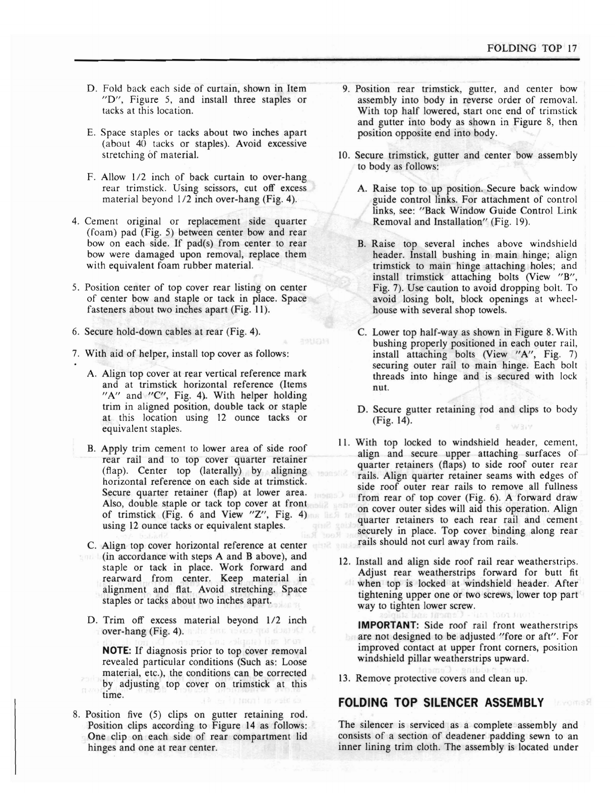
Fig. 13-Folding
Top
Silencer Assembly Attachment
I.
Front
Roof
Rail
6.
Trim Cement
8.
Silencer Listing
2.
Silencer Assembly Securing Silencer
to
Pocket
3.
Deadener
Pad Front Rail and
9.
Staple
4.
Front
Roof
Bow Tacking Strip
10.
Trim Cement in
5.
Side
Quarter
Padding
7.
Front
Roof
Rail
Shaded
Area
Tacking Strip Securing Silencer
to
Side
Quarter
Padding
the
folding
top at the front,
and
is
secured
around
its
2.
Reference
mark
front
edge
of
front
roof
rail
on
perimeter
as follows (Fig. 13): top cover. Also place
center
mark
on
cover
and
on
masked
section
of
front
roof
rail.
A. At the
front
roof
rail -
Cement
and
staples
3.
Detach
top cover
and
silencer assembly from
front
B.
At the
front
roof
bow -Slide-on listing pocket and
roof
rail (staples
and
cement).
Do
not
detach
side
staples
quarter
padding.
C.
At side
quarter
padding
-
Cement
4.
Raise top
and,
with front
roof
rail several inches
above
windshield
header,
detach
hold-down
cables at
front
(Fig. 4).
Removal
I.
With
top lowered to stacked position, remove
front
5.
Turn
back top cover
and
detach
cemented
side
roof
rail
front
weatherstrip. Detach front
roof
rail sections
of
silencer from side
quarter
padding
rear
weatherstrip
at
outer
ends (Fig. 3). (Fig. 13).
Popular Automobile Accessories manuals by other brands


InPOWER
InPOWER SS-FD23 owner's manual

Metra Electronics
Metra Electronics 108-TO7HG installation instructions

Enduro
Enduro SD260 Assembly instruction and safety regulations

STL
STL STRIKER 2 instruction manual

Aries
Aries S223015 installation manual

Truckman
Truckman Roll-Top Xtreme installation instructions