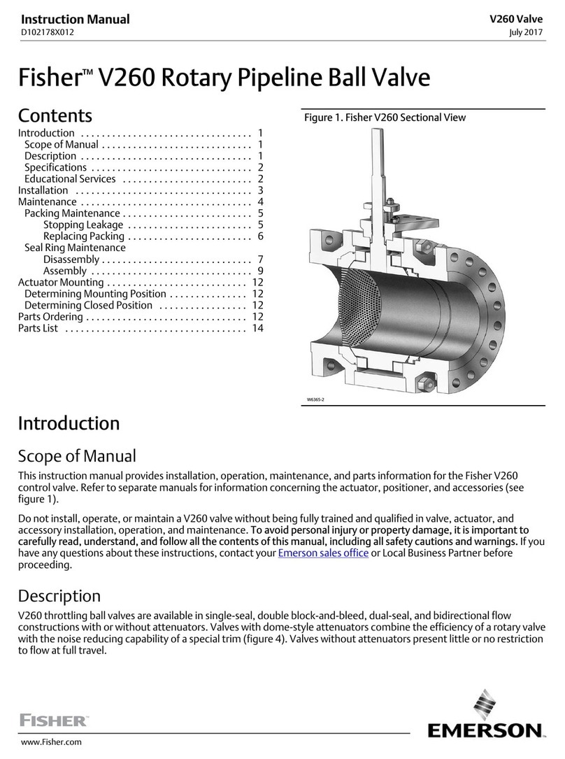
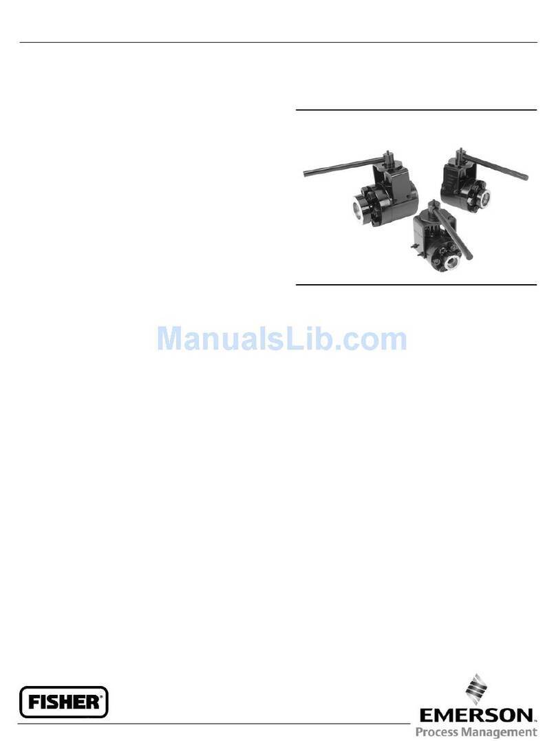
Fisher 461 User manual

www.Fisher.com
Fisher™461
Increased Outlet Angle Sweep-Flo Valve
Contents
Introduction 1.................................
Scope of Manual 1.............................
Description 1.................................
Specifications 2...............................
Educational Services 2.........................
Installation 2..................................
Maintenance 3.................................
Packing Lubrication 4..........................
Packing Maintenance 5.........................
Adding Packing Rings 5.....................
Replacing Packing 5........................
Replacing Trim 11.............................
Disassembly 11............................
Assembly 12..............................
Lapping Seating Surfaces 13....................
Parts Ordering 14...............................
Parts List 14...................................
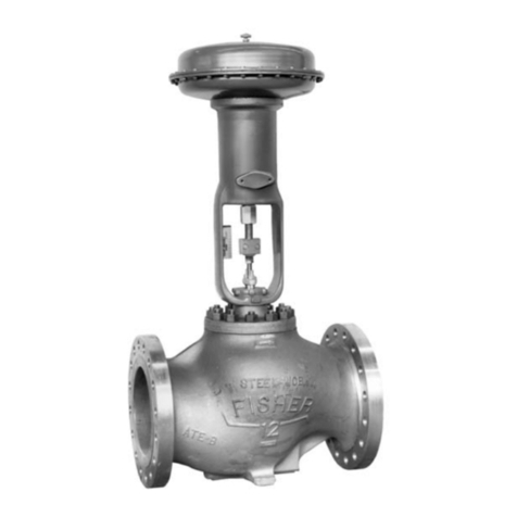
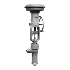
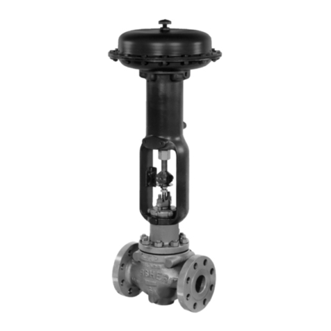
Figure 1. Fisher 461 Valve with 657 Actuator
W9553-2
Introduction
Scope of Manual
This instruction manual includes installation, maintenance, and parts information for the Fisher 461 anti-coke valve.
Refer to separate manuals for instructions covering the actuator, positioner, and accessories.
Description
The 461 valve (figure 1) is a self-cleaning, increased-outlet, angle valve that is typically used in the chemical and
hydrocarbon industries where control of residual oils or other liquids with coking properties is necessary. The 461
features a venturi-type throat, which is useful in power plants or slurry services where high pressure drops and flashing
might exist.
Do not install, operate, or maintain a 461 valve without being fully trained and qualified in valve, actuator, and
accessory installation, operation, and maintenance. To avoid personal injury or property damage, it is important to
carefully read, understand, and follow all the contents of this manual, including all safety cautions and warnings. If you
have any questions about these instructions, contact your Emerson sales office or Local Business Partner before
proceeding.
Instruction Manual
D100714X012
461 Valve
June 2017

Instruction Manual
D100714X012
461 Valve
June 2017
2
Table 1. Specifications
Valve Sizes (inlet size x outlet size)
NPS J2x3, J3x4, J4x6, and J6x8
Shutoff Classification per ANSI/FCI 70-2 and IEC
60534-4
Standard: Class IV
Optional: Class V
Flow Characteristic
Equal percentage Micro-Form flow characteristic in
the 12.7 to 31.8 mm (0.5 to 1.25 inch) port size and a
modified parabolic flow characteristic in the 38.1 to
114.3 mm (1.5 to 4.5 inch) port size.
Flow Direction
Flow down
Packing Arrangement
PTFE and graphite ribbon/filament are available as
standard packing.
Specifications
Specifications for the 461 valve are shown in table 1. If the valve is shipped with the actuator, some of the valve
specifications are on the valve nameplate, which is attached to the actuator. If the valve is shipped without the
actuator, the valve nameplate is wired to the valve.
Educational Services
For information on available courses for Fisher 461 valves, as well as a variety of other products, contact:
Emerson Automation Solutions
Educational Services - Registration
Phone: 1-641-754-3771 or 1-800-338-8158
E-mail: [email protected]
emerson.com/fishervalvetraining
Installation
WARNING
To avoid personal injury or equipment damage caused by sudden release of pressure, install the valve assembly only where
service conditions will not exceed the limits given on the appropriate nameplate.
Always wear protective gloves, clothing, and eyewear when performing any installation operations to avoid personal
injury.
Check with your process or safety engineer for any additional measures that must be taken to protect against process
media.
If installing into an existing application, also refer to the WARNING at the beginning of the Maintenance section in this
instruction manual.
1. Before installing a 461 valve, inspect it for any foreign material that may have collected during crating or shipping.
2. Check that the pipelines are free of pipe scale, chips, welding slag, and other foreign material.
3. Use accepted piping practices when installing the valve.

Instruction Manual
D100714X012
461 Valve
June 2017
3
4. Do not install the valve in a system where the service conditions exceed those specified when the valve was
ordered.
5. If continuous operation is required during maintenance and inspection, install a three-valve bypass around the valve
body so that it will be isolated.
6. Orient the valve body so that the flow will be in the direction indicated by the flow direction arrow located on the
outside of the valve body to ensure proper self-cleaning action.
7. If the actuator and valve are shipped separately, refer to the actuator mounting procedure outlined in the
appropriate actuator instruction manual.
8. If the valve body was shipped without packing installed in the packing box, install the packing before putting the
valve body into service. Refer to instructions given in the Packing Maintenance procedure.
WARNING
Personal injury could result from packing leakage. Valve packing was tightened before shipment; however, the packing
might require some readjustment to meet specific service conditions.
Valves with ENVIRO‐SEALtlive‐loaded packing or HIGH‐SEAL Heavy‐Duty live‐loaded packing will not require this
initial re‐adjustment. See the instruction manuals titled ENVIRO‐SEAL Packing System for Sliding‐Stem Valves,
D101642X012, or HIGH‐SEAL Live‐Loaded Packing System, D101453X012, (as appropriate) for packing instructions. If
you wish to convert your present packing arrangement to ENVIRO‐SEAL packing, refer to the retrofit kits listed in the
parts kit sub‐section near the end of this manual.
Maintenance
Valve parts are subject to normal wear and must be inspected and replaced as necessary. The frequency of inspection
and replacement depends upon the severity of service conditions.
WARNING
Avoid personal injury or property damage from sudden release of process pressure or bursting of parts. Before performing
any maintenance operations:
D Do not remove the actuator from the valve while the valve is still pressurized.
D Always wear protective gloves, clothing, and eyewear when performing any maintenance operations to avoid personal
injury.
D Disconnect any operating lines providing air pressure, electric power, or a control signal to the actuator. Be sure the
actuator cannot suddenly open or close the valve.
D Use bypass valves or completely shut off the process to isolate the valve from process pressure. Relieve process pressure
from both sides of the valve. Drain the process media from both sides of the valve.
D Vent the power actuator loading pressure and relieve any actuator spring precompression.
D Use lock-out procedures to be sure that the above measures stay in effect while you work on the equipment.
D The valve packing box may contain process fluids that are pressurized, even when the valve has been removed from the
pipeline. Process fluids may spray out under pressure when removing the packing hardware or packing rings, or when
loosening the packing box pipe plug.
D Check with your process or safety engineer for any additional measures that must be taken to protect against process
media.

Instruction Manual
D100714X012
461 Valve
June 2017
4
Note
If the valve has ENVIRO‐SEAL live‐loaded packing installed (figure 4), see the instruction manual entitled ENVIRO‐SEAL Packing
System for Sliding‐Stem Valves, D101642X012, for packing instructions.
If the valve has HIGH‐SEAL Heavy‐Duty live‐loaded packing installed (figure 4), see the instruction manual entitled HIGH‐SEAL
Live‐Loaded Packing System, D101453X012, for packing instructions.
Figure 2. Lubricator and Lubricator/Isolating Valve
LUBRICATOR
LUBRICATOR/ISOLATING VALVE
10A9421‐A
AJ5428‐D
A0832‐2
12
12
Packing Lubrication
Note
To avoid lubricants breaking down at elevated temperatures, do not lubricate packing used in processes with temperatures over
260_C (500_F).
WARNING
Do not lubricate parts when used in oxygen service, or where the lubrication is incompatible with the process media. Any
use of lubricant can lead to the sudden explosion of media due to the oil/oxygen mixture, causing personal injury or
property damage.
If a lubricator or lubricator/isolating valve (figure 2) is provided for PTFE/composition or other packings that require
lubrication, it will be installed in place of the pipe plug (key 12, figure 6). Use a good quality silicon‐base lubricant.
Packing used in oxygen service or in processes with temperatures over 260_C (500_F) should not be lubricated. To
operate the lubricator, turn the cap screw clockwise to force the lubricant into the packing box. The
lubricator/isolating valve operates the same way except the isolating valve must first be opened and then closed after
lubrication is completed.

Instruction Manual
D100714X012
461 Valve
June 2017
5
Packing Maintenance
If there is undesirable packing leakage in the spring‐loaded PTFE V‐ring packing shown in figure 3, tighten the packing
flange nuts (key 25, figure 6) until the shoulder on the packing follower (key 29, figure 6) contacts the bonnet (key 14,
figure 6). If leakage continues, replace the packing by following the numbered steps presented in the replacing
packing procedure.
If there is undesirable packing leakage with other than spring‐loaded PTFE V‐ring packing, first try to limit the leakage
and establish a stem seal by tightening the packing flange nuts (key 25, figure 6) to at least the minimum
recommended torque in table 2 or 3. However, do not exceed the maximum recommended torque in table 2 or 3 or
excessive friction may result. If leakage continues, replace the packing by following the numbered steps presented in
the Replacing Packing procedure.
If the packing is relatively new and tight on the valve plug stem, and if tightening the packing flange nuts does not stop
the leakage, it is possible that the stem is worn or nicked so that a seal cannot be made. The surface finish of a new
stem is critical for making a good packing seal. If the leakage comes from the outside diameter of the packing, it is
possible that the leakage is caused by nicks or scratches around the packing box wall. While replacing the packing
according to the Replacing Packing procedure, inspect the valve plug stem and packing box wall for nicks or scratches.
Adding Packing Rings
Key numbers referred to in this procedure are shown in figure 6, unless otherwise indicated.
When using packing with a lantern ring, it may be possible to add packing rings above the lantern ring as a temporary
measure without removing the actuator from the valve body.
1. Isolate the control valve from the line pressure, release pressure from both sides of the valve body, and drain the
process media from both sides of the valve. If using a power actuator, also shut off all pressure lines to the power
actuator, release all pressure from the actuator. Use lock‐out procedures to be sure that the above measures stay in
effect while you work on the equipment.
2. Remove the packing flange nuts (key 25) and lift the packing flange, upper wiper, and packing follower (keys 23, 16,
and 29) away from the valve body.
3. It may be possible to dig out the old packing rings on top of the lantern ring, but use care to avoid scratching the
valve plug stem or packing box wall. Clean all metal parts to remove particles that would prevent the packing from
sealing.
4. Remove the stem connector and slip the packing rings over the end of the valve plug stem.
5. Reassemble the packing follower, upper wiper, packing flange, and packing flange nuts (keys 29, 16, 23, and 25).
6. Reconnect the body‐actuator stem connection according to the appropriate actuator instruction manual.
7. Tighten the packing flange nuts only far enough to stop leakage under operating conditions. Check for leakage
around the packing follower when the valve is being put into service. Retighten the packing flange nuts as required
(see table 2 or 3).
Replacing Packing
WARNING
Refer to the WARNING at the beginning of the Maintenance section in this instruction manual.
Key numbers referred to in this procedure are shown in figure 6, unless otherwise indicated.
Instruction Manual
D100714X012
461 Valve
June 2017
6
1. Isolate the control valve from the line pressure, release pressure from both sides of the valve body, and drain the
process media from both sides of the valve. If using a power actuator, also shut off all pressure lines to the power
actuator, release all pressure from the actuator. Use lock‐out procedures to be sure that the above measures stay in
effect while you work on the equipment.
2. Remove the cap screws in the stem connector, and separate the two halves of the stem connector. Then exhaust all
actuator pressure, if any was applied, and disconnect the actuator supply and any leakoff piping.
Figure 3. Packing Arrangements
UPPER WIPER (KEY 16)
PACKING FOLLOWER
(KEY 29)
FEMALE ADAPTOR
(KEY 22)
V‐RING (KEY 19)
MALE ADAPTOR
(KEY 21)
WASHER (KEY 18)
SPRING (KEY 17)
PACKING BOX RING
(KEY 38)
LOWER WIPER
(KEY 39)
PACKING FOLLOWER
(KEY 29)
PACKING BOX RING
(KEY 38)
LANTERN RING
(KEY 30)
GRAPHITE FILAMENT
PACKING RING (KEY 20)
GRAPHITE RIBBON
PACKING RING (KEY 20)
1
2
12A8160‐A 14A3412‐C
PTFE V‐RING
SINGLE PACKING
GRAPHITE RIBBON AND FILAMENT
SINGLE PACKING
}KEY 22
UPPER WIPER (KEY 16)
PACKING FOLLOWER
(KEY 29)
FEMALE ADAPTOR
(KEY 22)
V‐RING (KEY 19)
MALE ADAPTOR
(KEY 21)
LANTERN RING (KEY 30)
PACKING BOX RING
(KEY 38)
LOWER WIPER
(KEY 39)
2
12A7839‐A Sht 1 14A3414‐C
PTFE V‐RING
DOUBLE PACKING
}KEY 22
GRAPHITE RIBBON AND FILAMENT
DOUBLE PACKING
1
1
PACKING FOLLOWER
(KEY 29)
PACKING BOX RING
(KEY 38)
LANTERN RING
(KEY 30)
GRAPHITE FILAMENT
PACKING RING (KEY 20)
GRAPHITE RIBBON
PACKING RING (KEY 20)
UPPER WIPER
(KEY 16)
PACKING
FOLLOWER
(KEY 29)
PACKING BOX RING
(KEY 38)
LANTERN RING
(KEY 30)
PACKING RING
(KEY 20)
12A8163‐A
PTFE/COMPOSITION
DOUBLE PACKING
NOTES:
0.102 mm (0.004 INCH) THICK SACRIFICIAL ZINC WASHERS. USE ONLY ONE BELOW EACH GRAPHITE RIBBON RING.
HAS THE APPEARANCE OF A WOVEN OR BRAIDED RING.
1
2
C0747‐1
3
3
33
3
3
3
3FOR A FLAT BOTTOM PACKING BOX, THESE PARTS ARE NOT NEEDED.

Instruction Manual
D100714X012
461 Valve
June 2017
7
Figure 4. ENVIRO-SEAL and HIGH-SEAL Packing Systems
W7018
W8532-1
FOLLOWER
PACKING
BOX
STUD
PACKING
SPRINGS
W8533-1
PACKING
BOX
STUD
FOLLOWER
PACKING
SPRING
W5803-3
SPRINGS
ANTI-
EXTRUSION
RING
LANTERN
RING
PACKING
BOX
STUDS
PACKING
RING
VALVE
BONNET
TYPICAL ENVIRO-SEAL PACKING SYSTEM
WITH PTFE PACKING
TYPICAL ENVIRO-SEAL PACKING SYSTEM
WITH GRAPHITE ULF PACKING
TYPICAL HIGH-SEAL PACKING SYSTEM
WITH GRAPHITE ULF PACKING
TYPICAL ENVIRO-SEAL PACKING SYSTEM
WITH DUPLEX PACKING
1FOR A FLAT BOTTOM PACKING BOX, THE PACKING BOX RING AND LOWER WIPER ARE NOT NEEDED.
1
1

Instruction Manual
D100714X012
461 Valve
June 2017
8
3. Remove the yoke locknut (key 26), and remove the actuator from the bonnet (key 14).
4. Loosen the packing flange nuts (key 25) so that the packing is not tight on the valve plug stem (key 10). Remove
any travel indicator disk and stem locknuts from the valve plug stem threads.
CAUTION
When lifting the bonnet (key 14), be sure that the valve plug and stem assembly (keys 3 and 10) remains on the seat ring
(key 2). This avoids damage to the seating surfaces as a result of the assembly dropping from the bonnet after being lifted
part way out. The parts are also easier to handle separately.
Use care to avoid damaging gasket sealing surfaces.
WARNING
To avoid personal injury or property damage caused by uncontrolled movement of the bonnet, loosen the bonnet by
following the instructions in the next step. Do not remove a stuck bonnet by pulling on it with equipment that can stretch
or store energy in any other manner. The sudden release of stored energy can cause uncontrolled movement of the bonnet.
If the liner sticks to the bonnet, proceed carefully with bonnet removal and support the liner so that it will not fall
unexpectedly from the bonnet.
Note
The following step also provides additional assurance that the valve body fluid pressure has been relieved.
5. Hex nuts (key 8) attach the bonnet to the valve body. Loosen these nuts approximately 3 mm (1/8 inch). Then
loosen the body‐to‐bonnet gasketed joint by either rocking the bonnet or prying between the bonnet and valve
body. Work the prying tool around the bonnet until the bonnet loosens. If no fluid leaks from the joint, proceed to
the next step.
6. Unscrew the hex nuts (key 8) and carefully lift the bonnet off the valve stem. If the valve plug and stem assembly
starts to lift with the bonnet, use a brass or lead hammer on the end of the stem and tap it back down. Set the
bonnet on a cardboard or wooden surface to prevent damage to the bonnet gasket surface.
7. Remove the valve plug (key 3), bonnet gasket (key 6) and the liner (key 5).
CAUTION
Inspect the liner, bonnet, and body gasket surfaces. These surfaces must be in good condition, with all foreign material
removed. Small burrs less than approximately 0.076 mm (0.003 inches) in height (the thickness of a human hair) can be
ignored. Scratches or burrs that run across the serrations are not permitted under any conditions, since they will prevent
the gaskets from sealing properly.
8. Clean all gasket surfaces with a good wire brush. Clean in the same direction as the surface serrations, not across
them.
9. Cover the opening in the valve body to protect the gasket surface and to prevent foreign material from getting into
the valve body cavity.
10. Remove the packing flange nuts (key 25), packing flange (key 23), upper wiper (key 16), and packing follower (key
29). Carefully push out all the remaining packing parts from the valve side of the bonnet using a rounded rod or
other tool that will not scratch the packing box wall.

Instruction Manual
D100714X012
461 Valve
June 2017
9
Figure 5. Installing Graphite Ribbon/Filament Packing Rings One at a Time
VALVE STEM
PACKING FOLLOWER
BONNET
TOP OF PACKING
RING EVEN WITH
BOTTOM OF
ENTRANCE
CHAMFER
INSTALLING
SECOND PACKING RING
A2207‐2
INSTALLING
FIRST PACKING RING
11. Clean the packing box and the following metal packing parts: packing follower, packing box ring, spring or lantern
ring, and, for single arrangements of PTFE V‐ring packing only, special washer (key 18).
12. Inspect the valve stem threads for any sharp edges that might cut the packing. A whetstone or emery cloth may
be used to smooth the threads if necessary.
13. Remove the protective covering from the valve body cavity, and install the liner. Install the plug and position the
new bonnet gasket (key 6) on top of the valve body. Then slide the bonnet over the stem and onto the studs (key 7).
Note
The prelubricated hex nuts (key 8) referred to in step 14 can be identified by a black film coating on the nut threads.
The proper bolting procedures in step 14 include‐‐but are not limited to‐‐ensuring that the bonnet stud threads are clean, and that
the hex nuts are evenly tightened to the specified torque values.
CAUTION
Failure to comply with good bonnet‐to‐body bolting practices and the torque values shown in table 4 may result in damage
to the valve. Cheater bars or slug wrenches should not be used for this procedure.
Hot torquing is not recommended.
14. Lubricate the stud threads, nut threads, and the faces of the hex nuts (key 8) with anti‐seize lubricant (not
necessary if new factory prelubricated hex nuts are used). Replace the hex nuts and tighten them finger‐tight.
Stroke the valve several times to center the trim. Torque the nuts in a crisscross pattern to no more than 1/4 of the
nominal torque value specified in table 4.

Instruction Manual
D100714X012
461 Valve
June 2017
10
When all nuts are tightened to that torque value, increase the torque by 1/4 of the specified nominal torque and
repeat the crisscross pattern. Repeat this procedure until all nuts are tightened to the specified nominal value. Apply
the final torque value again and, if any nut still turns, tighten every nut again.
Note
When installing packing rings, prevent entrapping air between the rings. Add the rings one at a time without forcing them below
the chamfer of the packing box entrance chamber. As each successive ring is added, the stack should not be pushed down more
than the thickness of the added ring (figure 5).
15. Install new packing and the metal packing box parts according to the appropriate arrangement in figure 3. If
desired, packing parts may be pre‐lubricated with a silicon base grease for easier installation. Slip a smooth‐edged
pipe over the valve stem, and gently tamp each soft packing part into the packing box, being sure that air is not
trapped between adjacent soft parts.
16. Slide the packing follower, wiper, and packing flange into position. Lubricate the packing flange studs (key 24) and
the faces of the packing flange nuts (key 25). Replace the packing flange nuts.
For the spring‐loaded PTFE V‐ring packing shown in figure 3, tighten the packing flange nuts until the shoulder on the
packing follower (key 29) contacts the bonnet.
For graphite packing, tighten the packing flange nuts to the maximum recommended torque shown in table 2. Then,
loosen the packing flange nuts, and retighten them to the recommended minimum torque shown in table 2.
For other packing types, tighten the packing flange nuts alternately in small equal increments until one of the nuts
reaches the minimum recommended torque shown in table 3. Then, tighten the remaining flange nuts until the
packing flange is level and at a 90‐degree angle to the valve stem.
For ENVIRO‐SEAL or HIGH‐SEAL live‐loaded packing, refer to the note at the beginning of the Maintenance section.
17. Mount the actuator on the valve body assembly, and reconnect the actuator and valve plug stems according to
the procedures in the appropriate actuator instruction manual.
Table 2. Recommended Torque for Graphite Type Packing Flange Nuts (non live-loaded)
VALVE STEM DIAMETER PRESSURE RATING
TORQUE
NSm lbfSft
mm Inches Min Max Min Max
19.1 3/4
CL600 21 31 15 23
CL900 27 41 20 30
CL1500 34 50 25 37
CL2500 41 61 30 45
25.4 1
CL600 35 53 26 39
CL900 42 62 31 46
CL1500 52 77 38 57
CL2500 61 91 45 67
31.8 1-1/4
CL600 49 74 36 55
CL900 56 83 41 61
CL1500 68 102 50 75
CL2500 81 122 60 90

Instruction Manual
D100714X012
461 Valve
June 2017
11
Replacing Trim
Refer to figure 6.
Disassembly
1. Remove the actuator and the bonnet according to steps 1 through 6 of the Replacing Packing section.
2. Remove the valve plug and stem assembly (keys 3 and 10) from the valve. If the stem needs to be replaced, drive
the pin (key 11) out, and unthread the stem from the plug.
CAUTION
Never use an old stem with a new valve plug. The use of an old stem requires drilling a new pin hole through the stem,
which will weaken the stem.
3. If the valve plug needs replacing, replace the entire valve plug and stem assembly. Do not reuse the old stem on a
new valve plug. If only a new stem is necessary, screw the plug onto the new stem. Drill a 4.8 mm (3/16 inch) hole
through the stem using the plug pin hole as a guide. Drive the pin into the stem and plug.
Table 3. Recommended Torque for PTFE Type Packing Flange Nuts (non live-loaded)
VALVE STEM DIAMETER PRESSURE RATING
TORQUE
NSm lbfSft
mm Inches Min Max Min Max
19.1 3/4
CL600 10 15 7 11
CL900 27 41 20 30
CL1500 34 50 25 37
CL2500 41 61 30 45
25.4 1
CL600 17 25 13 18
CL900 42 62 31 46
CL1500 52 77 38 57
CL2500 61 91 45 67
31.8 1-1/4
CL600 24 36 18 27
CL900 56 83 41 61
CL1500 68 102 50 75
CL2500 81 122 60 90
4. With the stem and valve plug assembly removed, slide the liner (key 5) out of the valve body. Inspect the seat ring
(key 2) for nicks and scratches. Make sure the valve plug and seat ring contact surfaces are free of nicks and
scratches.
5. To remove the liner (key 5), break it loose by using cap screws in the tapped holes located in the liner's flange. (In
some very hard materials, i.e., R30006, the holes have been omitted; therefore, a sleeve puller or similar device
must be used).
6. To replace the seat ring (key 2), remove the valve from the line, or remove the pipe connected to the flange. Then,
unthread the seat ring retainer (key 4), and remove the seat ring through the bottom of the valve body.

Instruction Manual
D100714X012
461 Valve
June 2017
12
Table 4. Recommended Torque for Valve Body to Bonnet Nuts
VALVE SIZE, NPS PRESSURE RATING STUD DIAMETER,
INCHES
TORQUE
B7/2H S20910
NSm lbfSft NSm lbfSft
2x3
CL300
7/8
373 275 339 250
CL600 373 275 339 250
CL900 373 275 339 250
CL1500 373 275 339 250
CL2500 1-1/8 522 385 522 385
3x4
CL300 7/8 373 275 339 250
CL600 373 275 339 250
CL900 1522 385 502 370
CL1500 522 385 502 370
CL2500 1-1/2 1247 920 1247 920
4x6
CL300 1522 385 502 370
CL600 522 385 502 370
CL900 1-1/4 942 695 942 695
CL1500 942 695 942 695
CL2500 1-3/4 2670 1970 2670 1970
6x8
CL300 1522 385 502 370
CL600 522 385 502 370
CL900 1-1/2 1247 920 1247 920
CL1500 1247 920 1247 920
Assembly
1. When assembling, use a new bonnet gasket (key 6), and wipe all sealing surfaces (valve body, bonnet, and gaskets)
with a clean cloth. If the seat ring (key 2) was removed, install it in the valve body (key 1), and then torque the seat
ring retainer (key 4) into the valve body. Since there is no gasket between the seat ring and the valve body, make
sure that the mating surfaces are clean and free of nicks and scratches.
2. Replace the liner (key 5). Then, slide the valve plug and stem assembly (keys 3 and 10) into the valve body (key 1).
3. Mount the bonnet (key 14) onto the valve body (key 1), being careful not to damage the gasket.
Note
If the seating surfaces of the valve plug and seat ring require lapping, refer to the Lapping Seating Surfaces section before
continuing to assemble the valve.
CAUTION
Avoid product damage in the following step by taking care not to damage the packing while installing the bonnet.
4. If it is necessary to replace the packing, perform steps 10 through 16 of the Replacing Packing section. However, if it
is not necessary to replace the packing, make sure to install the bonnet carefully on the valve body to avoid
damaging the packing with the valve stem threads.
5. Lubricate the valve body studs and nuts (key 7) with anti-seize lubricant, and install the nuts (key 8) on the bolts.
Tighten the nuts in a crisscross pattern to no more than 1/4 of the nominal torque value specified in table 4 to
ensure a positive seal and even pressure on the bonnet.

Instruction Manual
D100714X012
461 Valve
June 2017
13
When all nuts are tightened to that torque value, increase the torque by 1/4 of the specified nominal torque and
repeat the crisscross pattern. Repeat this procedure until all nuts are tightened to the specified nominal value. Apply
the final torque value again and, if any nut still turns, tighten every nut again.
Note
It may be necessary to repeat the bolting pattern several times until the bonnet-to-body seal is made since the tightening of one
nut might loosen an adjacent nut. It is recommended that the pattern be repeated until none of the nuts will turn at the
recommended torque.
6. Mount the actuator on the bonnet, and make up the stem connection according to the procedure given in the
appropriate actuator instruction manual.
Lapping Seating Surfaces
A certain amount of leakage should be expected with metal-to-metal seating in any valve body. If the leakage becomes
excessive, however, the condition of the seating surfaces of the valve plug and seat ring can be improved by grinding.
Large nicks should be machined out rather than ground out. Use a commercial lapping compound or a mixture of
600-grit Carborundum and solidified vegetable oil. Apply the compound to the bottom of the valve plug, and apply
white lead to the seat ring to prevent excessive tearing or cutting during lapping. The white lead should not be mixed
with the grinding compound, but rather applied separately.
The valve must be assembled to the extent that the valve plug and stem assembly (keys 3 and 10) and the seat ring
(key 2) are in place and the bonnet (key 14) is bolted to the valve body (key 1). A simple handle can be made from a
piece of strap iron locked to the valve plug stem with nuts. Rotate the handle alternately in each direction to lap the
seats. After lapping, remove the bonnet, and clean the seating surfaces. Completely assemble as described in the
Assembly part of the Maintenance section, and test the valve for shutoff. Repeat the lapping procedure if leakage is
still excessive.

Instruction Manual
D100714X012
461 Valve
June 2017
14
Parts Ordering
Each body-bonnet assembly is assigned a serial number, which is on the body nameplate. The serial number also
appears on the actuator nameplate if you bought a valve and actuator assembly. Refer to this serial number when
contacting your Emerson sales office or Local Business Partner for technical advice. When ordering replacement parts,
mention this serial number. Also specify key number and part description following Parts List.
WARNING
Use only genuine Fisher replacement parts. Components that are not supplied by Emerson Automation Solutions should
not, under any circumstances, be used in any Fisher valve, because they may void your warranty, might adversely affect the
performance of the valve, and could cause personal injury and property damage.
Parts List
Note
Contact your Emerson sales office or Local Business Partner for Part
Ordering information.
Key Description
1 Valve Body
If you need a valve body as a replacement part, order by valve
size, serial number, and desired material.
2* Seat Ring
3* Valve Plug
4* Seat Ring Retainer
5* Liner
6* Gasket, N04400
7 Stud Bolt, (8 req'd for NPS 2x3 through NPS 4x6,
12 req'd for NPS 6x8)
8 Hex Nut, (12 req'd for NPS 6x8, 8 req'd for all other sizes)
Key Description
9 Line Position Pin
10 Valve Stem
11* Pin, S31600 SST
12 Pipe Plug, Lubricator, or Lubricator/Isolating Valve
14 Bonnet
If you need a bonnet as a replacement part, order by valve size
and stem diameter, serial number, and desired material.
16* Upper Wiper, felt
17 Spring
18 Washer
19* Packing Ring, PTFE
21* Male Adaptor
22* Female Adaptor
23 Packing Flange
24 Packing Stud (2 req'd)
25 Packing Nut (2 req'd)
26 Yoke Locknut
29 Packing Follower
33 Companion Flange
34* Gasket, N04400, (2 req'd)
35 Stud Bolt (4 req'd)
36 Hex Nut (4 req'd)
37 Equalizing Connection
40 Nameplate
41 Wire
42 Drive Screw
*Recommended spare parts

Instruction Manual
D100714X012
461 Valve
June 2017
15
Figure 6. Fisher 461 Valve Assembly
KEYS 33, 34, 35, 36, 37, 40, 41, AND 42 NOT SHOWN

Instruction Manual
D100714X012
461 Valve
June 2017
16
Actuator Groups (by Type Number)
Group 1
90 mm (3-9/16 Inch) Yoke Boss
Group 100
127 mm (5 Inch)
Yoke Boss
585C
657 and 667—76.2 mm (3 Inch) Travel
1008
585C
657
1008
Group 101
127 mm (5 Inch)
Yoke Boss
667
Emerson Automation Solutions
Marshalltown, Iowa 50158 USA
Sorocaba, 18087 Brazil
Cernay, 68700 France
Dubai, United Arab Emirates
Singapore 128461 Singapore
www.Fisher.com
The contents of this publication are presented for informational purposes only, and while every effort has been made to ensure their accuracy, they are not
to be construed as warranties or guarantees, express or implied, regarding the products or services described herein or their use or applicability. All sales are
governed by our terms and conditions, which are available upon request. We reserve the right to modify or improve the designs or specifications of such
products at any time without notice.
E1981, 2017 Fisher Controls International LLC. All rights reserved.
Fisher and ENVIRO-SEAL are marks owned by one of the companies in the Emerson Automation Solutions business unit of Emerson Electric Co. Emerson
Automation Solutions, Emerson, and the Emerson logo are trademarks and service marks of Emerson Electric Co. All other marks are the property of their
respective owners.
Neither Emerson, Emerson Automation Solutions, nor any of their affiliated entities assumes responsibility for the selection, use or maintenance
of any product. Responsibility for proper selection, use, and maintenance of any product remains solely with the purchaser and end user.
Table of contents
Other Fisher Control Unit manuals

Fisher
Fisher EAS easy-e User manual

Fisher
Fisher EUT-2 User manual

Fisher
Fisher Z500 User manual

Fisher
Fisher ET easy-e User manual

Fisher
Fisher D2T FloPro User manual

Fisher
Fisher HPA User manual

Fisher
Fisher V150S User manual

Fisher
Fisher 8590 User manual

Fisher
Fisher A31A Manual

Fisher
Fisher TBX-T User manual

Fisher
Fisher Control-Disk User manual

Fisher
Fisher Design ED series User manual

Fisher
Fisher Vee-Ball V150 User manual

Fisher
Fisher EHD User manual

Fisher
Fisher NotchFlo DST CL300 User manual

Fisher
Fisher 1808 User manual

Fisher
Fisher Z500 User manual

Fisher
Fisher 167D User manual

Fisher
Fisher FIELDVUE DVC2000 User manual

Fisher
Fisher Vee-Ball V150 User manual