manuals.online logo
Brands
  1. Home
  2. •
  3. Brands
  4. •
  5. Fisher
  6. •
  7. Tools
  8. •
  9. Fisher 75394 User manual

Fisher 75394 User manual

1. Do not use reel at higher pressures or temperatures than listed on
the back of this bulletin.
2. Remove all spring tension before beginning disassembly process.
SAFETY
Dimensions
A 14 3/8”
B 14”
C 9 3/4”
D 2 1/2”
E 6 1/8”
INSTALLATION: A flexible hose connection must be used between the hose reel inlet and the source of supply to prevent possible
misalignment and binding. Turn over the page for more detailed instructions and drawing configuration.
This reel is configured to be wall mounted. The hose reel is equipped with a universal mounting bracket so that it can
be mounted on the floor, wall or ceiling. In order to modify it’s factory set position the hose guide arm can be moved
to the position desired by removing the screws fastening the guide bracket to the reel base. Shift the guide arm bracket
so the hose comes off the reel at the desired position and replace the screws. NOTE: For proper installation in wall mount
applications, ensure reel is mounted with inlet on the right as you are facing the reel. Failing to do so could cause latching issues.
Hose reel spring and bearings are factory lubricated and require no further lubrication.
LUBRICATION:
REPLACING HOSE:
1. Wind spool flange clockwise-facing swivel-until spring is tight.
2. Back off three turns and latch.
3. Insert hose through roller guide.
4. Connect hose fitting to swivel joint and secure hose with clamps.
ADJUSTMENTS: To adjust spring tension, add or remove wraps of hose from the spool, one wrap at a time until desired tension is
obtained.
REPAIRS: Extensive repairs should be performed only by an authorized serviceman or factory to avoid damage which may
void your warranty. Remove all spring tension before beginning disassembly process.
MOUNTING:
Operating Instructions
Model:75394
Spring Driven Reel
Fisher Manufacturing Co. • 1900 “O” Street, Tulare, CA 93274
Ph: 800-421-6162 / 559-685-5200 • Fax: 800-832-8238 / 599-685-5222
Part No.75432 Rev.A
Model: 75394 Spring Driven Hose Reel
Model: 75430 Reel Kit Pro Spray Valve
Page 2
Item # Description # Req. 75394
2980-R027
33324
9 Bumper Stop Assembly 1
10 Hose Assembly 1
14 Drive Spring 1
31 Swivel Assembly 1
32 Swivel Union 1
Hose I.D. and Length 3/8” x 35 FT
Reel Inlet Connection 3/8” F.P.T.
Max. Operating Pressure 200 P.S.I.
Max. Operating Temperature 160 °F
Item # # Req. Description
Item # Req.# Part Description
Item # # Req. Description Item # # Req. Description
12
1” Snap
31 175066 Hose RR 3/8m x 1/2f x 1 1/2 ft
32
33
12913-3/8 Handle 3/4-14f X 3/8f
34
12922-5000 Gasket Handle
35
12990 Pro Spray Valve
1
3298 PST Thread Sealant
Ring 11 1 Guide Arm Assembly 21 1 Latch Bushing
22
Spacing Washer 12 1 Base Assembly 22 1 Latch Spring
33
1/4-10 x 5/8”
Self Tapping Screw 15 1 Spring Case Stud 24 1 O-ring
41
Sheave Flange 16 1 3/8-16 x 1/2” Set Screw 25 1 Latch Plate Assembly
51
Sheave Disk 17 1 Spring Case & Hub Assembly 26 1 10-32 x 1” Machine Screw
61
Latch Cam 18 8 10-32 x 3/8” Nyloc Nut 27 1 U-bolt Hose Clamp
72
Spring Arbor 19 1 Latch Plate Bumper 28 2 1/4-20 Nyloc Nut
87
10-32 x 1/2” Machine Screw 20 1 10-24 x 3/8”Self Tapping Screw 30 1 Main Shaft
31
32
33
34
35
1. Connect the lead-in line (31) to the reel (75394) inlet located on the right-hand side of the hose reel,
by applying PST (35) or plumbers tape on the male 3/8” NPT threads on the lead-in line (31) and thread it
to the reel (75394) using a wrench to support the swivel while tightening the lead-in line.
2. Connect the 1/2” female end of the lead-in line (31) to the water supply using PST (35) or plumbers tape
and tighten.
3. Turn on water supply and flush the reel line to remove any debris from the reel for a few seconds and
then turn off water supply.
4. Attach the handle (32) to the reel hose (10). By applying PST (35) or plumbers tape on the 3/8” NPT male threads on reel hose
and tighten.
6. Insert the gasket handle (33) into the handle (32) and then connect the pro spray valve (34).
7. Turn water supply on and check for leaks.
NOTE: Apply PST or Plumber Tape on
the following locations to prevent any
leaks.
1
1
1
Page 1
Read this manual carefully before installing, operating or
servicing this equipment.
IMPORTANT
Dimensions
A 20 1/4”
B 19 3/4”
C 7 13/16”
D 3 7/8”
E7”
SAFETY
Personal injury and/or equipment damage may result
if proper safety precautions are not observed.
• Ensure that reel is properly installed before connecting
input and output hoses.
• Bleed fluid/gas pressure from system before servicing
reel.
• Before connecting reel to supply line, ensure that
pressure does not exceed maximum working pressure
rating of reel.
• Remember, even low pressure is very dangerous
and can cause personal injury or death.
• Be aware of machinery and personnel in work area.
• If a leak occurs in the hose or reel, remove system
pressure immediately.
Operating Instructions
Model:
Wall Mounted Spring Driven Reel
• A high tension spring assembly is contained within the reel.
Exercise extreme caution.
• Pull hose from reel by grasping the hose itself, not the control
valve.
• Ensure that reel, hose, and equipment being serviced
are properly grounded. Use an ohmmeter to check ground
continuity.
• If reel ceases to unwind or rewind, remove system pressure
immediately. Do not pull or jerk on hose!
• Treat and respect the hose reel as any other piece of
machinery, observing all common safety practices.
Fisher Manufacturing Co. • 1900 “O” Street, Tulare, CA 93274
Ph: 800-421-6162 / 559-685-5200 • Fax: 800-832-8238 / 599-685-5222
Part No.75421 Rev.A
75395 50 ft Hose with Spray Valve
Page 2
Spring Driven Hose Reels
INSTALLATION INSTRUCTIONS
MOUNTING
Caution: Unless reel was specified
differently when ordering, maximum
installation height is 16 feet. Do not
exceed this distance.
1. Unpack and inspect reel for damage.
Turn by hand to check for smooth
operation. Check for completeness.
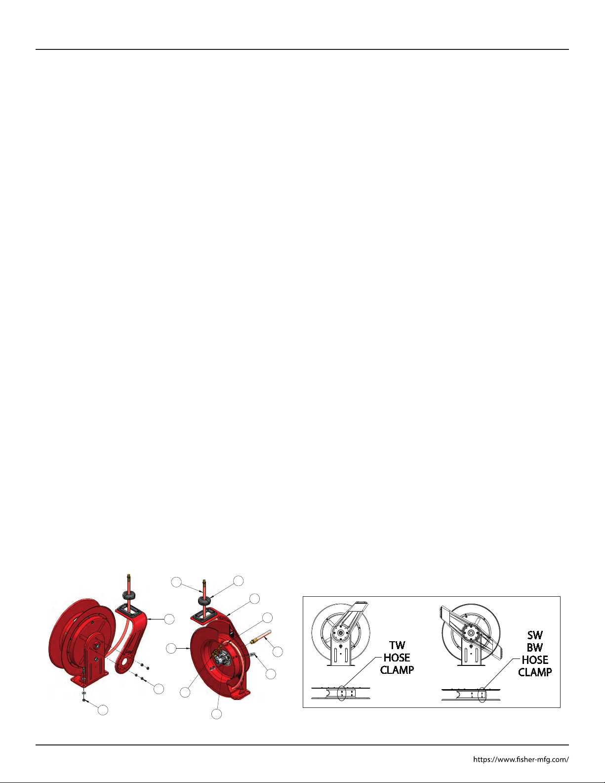
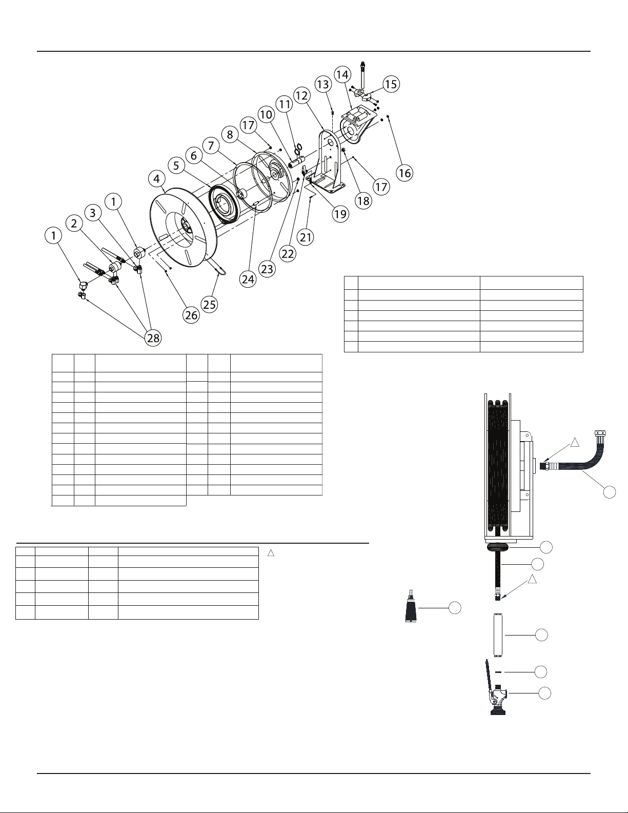
2. Configure reel for top, side or
bottom-wind hose dispensing by
removing nuts (1) securing guide arm
bracket (2). Position guide arm bracket
to desired location, and replace nuts.
Caution: When changing guide arm
positions, the U-bolt must be placed in
the proper location as instructed in
figure A below. The reel can
“latch out” during use if this
instruction is not adhered to.
3. Position reel on floor, wall, or ceiling.
Secure into place using four (customer
supplied) bolts (3).
INSTALLING THE INPUT HOSE(S)
Warning: Ensure that supply line
pressure does not exceed maximum
working pressure rating of reel. Apply
pipe thread sealant to all threads.
Caution: Use flexible hose connection at
input. Do not use rigid plumbing.
1. Connect supply line hose (4) to main
shaft input (5) as indicated in
illustration.
INSTALLING THE OUTPUT HOSE(S)
Warning: Use extreme caution; reel
under tension. Avoid releasing latch
mechanism. Apply pipe thread sealant to
all threads.
1. Manually turn sheave (10) until spring
is tight, back off 3 turns, then latch.
2. Route output hose(s) (11) through
guide arm bracket (2), U-bolts (12),
then through cutout (13) in spool as
indicated in illustration.
3. Connect output hose(s) (11) to swivel
(14) as indicated in illustration.
4. Tighten U-bolts (12).
5. Charge hose(s). Momentarily open
control valve to purge hose(s) of gases.
When fluid appears at control valve,
close valve. With hose(s) fully charged,
release latch and wind output hose(s)
onto reel.
ADJUSTMENTS
Warning: Use extreme caution; reel
under tension. Avoid releasing latch
mechanism. If necessary, adjust spring
tension on reel by adding or removing
wraps of hose from spool, one wrap at a
time, until desired tension is obtained.
Add wraps to increase tension. Remove
wraps to decrease tension.
SERVICE INSTRUCTIONS
User servicing of the reel is limited to
replacing input/output hoses only. Refer
all other repairs to an authorized service
person or directly to Reelcraft. Failure to
do so can result in personal injury and/or
equipment damage and may void the
warranty. Warning: Rewind hose on
reel, then bleed pressure from system
before performing the following proce-
dures.
1. Replace hoses in accordance with
procedures given in “Installation
Instructions” section of this manual
Caution: When replacing drive spring,
hold the center of the spring down as the
hub is pulled out. If the center is allowed
to raise up, the spring may escape from
it’s container with enough force to cause
injuries.
When disposing of old or broken spring
assemblies, the coils should be welded or
wired together to prevent possible injury
to scrap handling personnel.
2. All mating moving parts are to be
lubricated with Perma Bond or Loctite
anti-seize compound.
Figure A
3
1
5
2
4
14
10
11 15
13
12
2
Spring Driven Hose Reels
Model: 75431 Reel Kit Pro Spray Valve
Page 3
Item
#Description
#
Req.
Item
#Description
#
Req.
75395
1 Swivel Assembly1
3 90° Ell1
4 Sheave Assembly1
5 Drive Spring Assembly1
6 Spring Arbor Assembly1
7 Gasket1
8 Spring Case Assembly1
9 10-32 Hex Locknut6
10 Main Shaft1
11 1 1/4” Snap Ring2
12 Base Assembly1
13 1/2-13 Set Screw1
14 Guide arm with Rollers
1
15 Bumper Stop Assembly
1
16 5/16-18 Locknut4
17 10-32 x 3/8” Nyloc Nut1
18 1/2-20 x 5/8” Hex Nut1
19 Latch Spring1
21 10-32 Shoulder Screw1
22 Latch Pawl Assembly1
23 3/8-24 Jam Nut1
24 Spring Case Stud1
25 U-bolt1
26 1/4-20 X 3/8” Locknut4
28
29
30
Swivel Union1
Hose Assembly
Reel Model
2980-R027Bumper Stop Assembly
33332
Hose I.D. x Length 3/8” X 50’
Reel Inlet Connection 1/2” FPT
Max. Operating Pressure 200 PSI
Max. Operating Temperature 160 °F
NOTE: Apply PST or Plumber Tape on
the following locations to prevent any
leaks.
1
35
32
33
34
29
30
31
Item # Req.# Part Description
31 133413 Hose RRA 1/2m X 1/2f X 2 ft
32
33
12913-3/8 Handle 3/4-14f X 3/8f
34
12922-5000 Gasket Handle
35
12990 Pro Spray Valve
13298 PST Thread Sealant
1. Connect the lead-in line (31) to the reel (75395) inlet located on the right-hand side of the hose reel,
by applying PST (35) or plumbers tape on the male 1/2” NPT threads on the lead-in line (31) and thread it
to the reel (75395) using a wrench to support the swivel while tightening the lead-in line.
2. Connect the 1/2” female end of the lead-in line (31) to the water supply using PST (35) or plumbers tape
and tighten.
3. Turn on water supply and flush the reel line to remove any debris from the reel for a few seconds and
then turn off water supply.
4. Attach the handle (32) to the reel hose (30). By applying PST (35) or plumbers tape on the 3/8” NPT male threads on reel hose
and tighten.
5. Insert the gasket handle (33) into the handle (32) and then connect the pro spray valve (34).
6. Turn water supply on and check for leaks.
1
1

Other Fisher Tools manuals

Fisher 29841 User manual

Fisher

Fisher 29841 User manual

Fisher 29801 User manual

Fisher

Fisher 29801 User manual

Popular Tools manuals by other brands

DeWalt DWP690 instruction manual

DeWalt

DeWalt DWP690 instruction manual

Cornwell Tools CAT120 operating manual

Cornwell Tools

Cornwell Tools CAT120 operating manual

Westfalia 16 38 24 instruction manual

Westfalia

Westfalia 16 38 24 instruction manual

Ripley WS5-M operating instructions

Ripley

Ripley WS5-M operating instructions

TREND PFJ/SET/1 manual

TREND

TREND PFJ/SET/1 manual

5th Axis V75150X VISE owner's manual

5th Axis

5th Axis V75150X VISE owner's manual

Southwire Triggers TSS-01 operating instructions

Southwire

Southwire Triggers TSS-01 operating instructions

molex 64005-0400 Specification sheet

molex

molex 64005-0400 Specification sheet

Ryobi ACWB1 quick start guide

Ryobi

Ryobi ACWB1 quick start guide

CMT ORANGE TOOLS CMT200 Operating/safety instructions

CMT ORANGE TOOLS

CMT ORANGE TOOLS CMT200 Operating/safety instructions

XPOtool 62565 user manual

XPOtool

XPOtool 62565 user manual

M7 SQ-0217 quick start guide

M7

M7 SQ-0217 quick start guide

ReelCraft 7000 Series operating instructions

ReelCraft

ReelCraft 7000 Series operating instructions

Hilti SCO 6-22 operating instructions

Hilti

Hilti SCO 6-22 operating instructions

Festool TP 220 Original operating manual

Festool

Festool TP 220 Original operating manual

Beta 1931CD13 instructions

Beta

Beta 1931CD13 instructions

Bostitch BT1855 Original instructions

Bostitch

Bostitch BT1855 Original instructions

BGS technic 69506 instruction manual

BGS technic

BGS technic 69506 instruction manual

manuals.online logo
manuals.online logoBrands
  • About & Mission
  • Contact us
  • Privacy Policy
  • Terms and Conditions

Copyright 2025 Manuals.Online. All Rights Reserved.