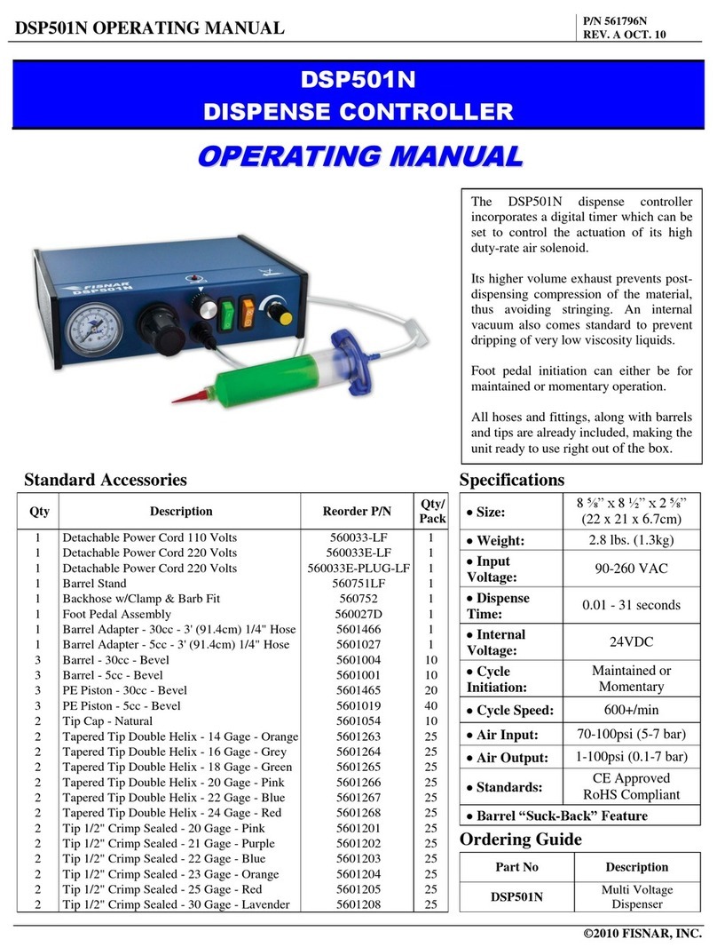
FISNAR VC300 User manual

VC300 Pneumatic Valve Controller Operating Manual
© 2021 Fisnar - 2 - VC300 Rev 01
Table of Contents
Machine Overview 3
Product Safety Statements 4
Specifications 6
Accessories 6
External Controls 7
Front
8
Back
11
Control Buttons
13
Machine Setup 15
Dispense Setup 17
Timing Diagram 19
Dispense Modes 20
Manual Mode
20
Timed Mode
22
Cycle Mode
26
Function Menu 29
Auto Cycle Stop
30
Low Pressure Alarm
31
Low Pressure Limit
32
P-Unit
33
Program Version
34
External Machine Actuation 35
I/O Specification 36
Schematic
36
Output Signal Logic
37
Input Signal Logic
38
Output Signal Definition
39
Input Signal Definition
40
Spare Part List 41
Troubleshooting 42

VC300 Pneumatic Valve Controller Operating Manual
© 2021 Fisnar - 3 - VC300 Rev 01
OVERVIEW
Model VC300 Pneumatic Valve Controller
The VC300 is a sophisticated controller able to control the operation of pneumatic dispensing
valves with a spring return closing action or air actuated closing action. The high speed,
internal 5/2 way pneumatic solenoid valve is able to rapidly actuate and shut off the dispense
valve, to prevent drooling and achieve consistent and repeatable dispense results.
The plug & play pneumatic push-in style fittings on the back of the controller, ensure it can be
quickly and easily configured when actuating a pneumatic dispense valve fitted with a
mechanical spring return closing action.
The controllers bright multi-line LED display provides easy user-friendly programming and
visualization of the dispense parameters and conditions. While an integrated pressure
regulator and gauge offer the added benefit in allowing the controller to control both dispense
valve actuation and the fluid pressure being supplied to the dispense valve. This results in a
simple and compact valve system setup, with less external fittings & components being used
at risk of damage and leakages.
Three Operation Modes
A manual mode – The dispense operation is manually controlled by a foot pedal.
A timed mode – Dispenses at a pre-set time for controlled, repeatable shot sizes.
A cycle mode – Continually dispenses at a pre-set time and at a pre-set interval.
One programmable memory slot.
Adjustable fluid output pressure (0-100psi) for setting and controlling pressure of fluid reservoir
connected to the dispense valve.
Compatible with pneumatic dispense valves fitted with a spring return or air actuated closing action
Digital timer display (0.008-99.99 seconds).
7 channel I/O circuit for external control and robot integration
Air input alarm for monitoring consistent system input pressure
Industry standard ¼” air-output connector ensures easy system installation and integration into
workplace environments
Compact & durable aluminum housing designed for industrial work environments.
Worldwide compatible power supply.

VC300 Pneumatic Valve Controller Operating Manual
© 2021 Fisnar - 4 - VC300 Rev 01
General Precautions
Do not operate the machine in excess of its maximum ratings / settings.
Make sure that the input air supply is clean and dry. A 5 micron air filter/regulator
(item number 560567) is supplied and recommended to use, so as to ensure the
input air supply is clean and dry.
If Cyanoacrylates adhesives or other moisture sensitive fluids are being used,
an inline coalescing filter (item number 560779C) must be installed to maintain
dispensing system performance
The fluid being dispensed may be toxic and / or hazardous. Refer to the Material
Safety Data Sheet for proper handling and safety precautions.
Do not smoke or use near an open flame when flammable materials are being
dispensed.
Do not expose the machine directly to sunlight.
Avoid cleaning the machine with aggressive solvents – neutral detergents are
preferred.
VC300 Malfunction
If the machine malfunctions, shut down the machine immediately. This can be
done by either pushing the power switch at the back of the unit into the off
position or disconnecting the power cord.
Isolate pneumatic air supply to the controller.
Identify the cause of machine malfunction and fix accordingly before switching
back on.
SAFETY

VC300 Pneumatic Valve Controller Operating Manual
© 2021 Fisnar - 5 - VC300 Rev 01
Inappropriate Use
If the machine is used in a way other than described in this manual, it may cause damage
to self or property.
Do not use any components with the machine other than Fisnar authorized
components.
Do not use incompatible materials.
Do not make any modifications to the machine.
All repairs are to be done using Fisnar specified spare parts.
Do not operate the machine in excess of its maximum ratings / settings.
Fire Prevention
Refer to the following instructions to avoid any fire or explosion.
Assess your surroundings and the location of the nearest fire extinguisher and
Emergency Exit.
Do not smoke or use near an open flame when flammable materials are being
dispensed.
Immediately disconnect power if any sparking or smoke appears.
Do not expose the machine directly to sunlight.
Maintenance
The VC300 is generally a maintenance free machine. However, to ensure smooth
operation please follow the below instructions.
Only use non-woven cleaners on the machine.
Periodically inspect pneumatic and fluid tubing for signs of fatigue and replace
as necessary
Ensure that compressed air supply to the machine is clean and moisture free.
Periodically check electrical connections and pneumatic fittings are secure.
SAFETY

VC300 Pneumatic Valve Controller Operating Manual
© 2021 Fisnar - 6 - VC300 Rev 01
ACCESSORIES
Item Description Quantity
5601911 Power Adaptor (Input: 100 – 240 VAC / Output: 24 VDC) 1
5601888 Foot Pedal 1
560567 5 Micron Air Filter 1
5801060-10FT 1/4" OD x 1/8” ID Polyurethane Tubing – 10FT 1
560746A Straight 1/4" OD Push Connector x 1/4" NPT Male 3
560716 Nipple ¼” NPT Male 1
560945 Street T 1/4” NPT Male x 1/4" NPT Female 1
580057 Female Quick Connect x 1/4” NPT Male Fitting 1
51495K173 1/4” OD Push to Connect Air Plug 2
5779K712 Push To Connect Air Fitting 1/4" Stem OD X 5/32" Tube OD 3
2146T13 15 Pin D-Sub Connector Plug 1
SPECIFICATIONS
Dimensions (W x D x H): 7.56” x 5.04” x 3.00” (192 x 128 x 76 mm)
Weight: 2.36 lbs (1.07 kg)
Input AC to Power
Supply:
100 – 240 VAC, 50 / 60 Hz
Output DC from Power
Supply: 24 VDC – 1 Amp
Cycle Rate: Up to 600 cycles / min
Relative Humidity: 20 – 90% (No Condensation)
Operating Temperature: 50 – 104
℉ (
10 – 40
℃)
Timer: 0.008 – 99.99 seconds
Air Input: 100 psi (7 bar) max
Air Output: 1 – 100 psi (0.07 – 7 bar)
Standards: CE Approved, UKCA Approved, EMC Compliant,
RoHS Compliant

VC300 Pneumatic Valve Controller Operating Manual
© 2021 Fisnar - 7 - VC300 Rev 01
EXTERNAL CONTROLS
FIG. 1: External Controls - Overview
Item
Illustration Item Illustration Item Illustration
1 Air Pressure Gauge 7 Scroll Down Button 13 Power On/Off Switch
2 Set Button 8 Air Pressure Regulator 14 Valve Close Air Out
Port
3 Mode Button 9 Display 15 Exhaust Port
4 Function Button 10 Foot Switch Connector 16 Fluid Air Out Port
5
Scroll Up Button
11
Power Input Connector
17
Air Inlet Port
6 Shot Button 12 I/O Connector 18 Valve Open Air Out
Port
REAR
FRONT
9
7
1
8
2
4
6
3
5
17
13
18
10
11
12
14
15
16

VC300 Pneumatic Valve Controller Operating Manual
© 2021 Fisnar - 8 - VC300 Rev 01
EXTERNAL CONTROLS
FIG. 2: External Controls – Front
1. Air Pressure
Gauge
Shows the amount of pressure being used to pressurize the fluid feed
system that is feeding the dispense fluid into the valve.
The pressure gauge value is set and controlled by the pressure regulator
(3).
The set pressure is fed out of the machine to the external fluid feed
system from the “Fluid Air Out” port (16).
1
3
2
TIM AL1 IN 0 psi
1.
234 s
A
B
C
D

VC300 Pneumatic Valve Controller Operating Manual
© 2021 Fisnar - 9 - VC300 Rev 01
2A. Digital Display
Screen
In MANUAL mode, when the foot pedal switch or shot button is pressed
or an external machine actuation input signal is received, the dispense
valve will be actuated to start dispensing fluid. The machine will also
begin counting up from 0.000 seconds.
When the foot pedal switch or shot button is released or an external
machine actuation input signal is removed, the dispense valve will stop
being actuated and dispensing of fluid will stop. The machine will display
and hold the dispense cycle time until the next actuation cycle.
When the foot pedal switch or shot button is pressed again or an external
machine actuation input signal is received again, the timer will
automatically reset and start counting up from 0.000 seconds, and the
dispense valve will be actuated to start dispensing fluid again.
When in TIMED mode, the saved dispense time (seconds) will be
displayed. When the foot pedal switch or shot button is pressed or an
external machine actuation input signal is received, the dispense valve
will be actuated to start dispensing fluid. The machine will also begin
counting up from 0.000 seconds until it reaches the saved dispense time.
Once the saved dispense time has been reached, the dispense valve
will stop being actuated and dispensing of fluid will stop. The machine
will display and hold the dispense cycle time until the next actuation
cycle.
One (1) individual program is saved to the machine and automatically
recalled when the machine is powered back on.
When in CYCLE mode, the saved dispense time (seconds) will be
displayed. When the foot pedal switch or shot button is pressed or an
external machine actuation input signal is received, the dispense valve
will be actuated to start dispensing fluid. The machine will also begin
counting up from 0.000 seconds until it reaches the saved dispense time.
Once the saved dispense time has been reached, the dispense valve
will stop being actuated and dispensing of fluid will stop. The machine
will then automatically start counting down from the time set in the “P00.
Auto Cycle Stop” function setting to 0.000 seconds.
Once the machine has counted down to 0.000 seconds, the dispense
valve will automatically be actuated to start dispensing fluid again. The
machine will also automatically begin counting up from 0.000 seconds
until it reaches the saved dispense time.
This looping cycle will continue to be repeated until the foot pedal switch
or shot button is pressed again or an external machine actuation input
signal is received again.

VC300 Pneumatic Valve Controller Operating Manual
© 2021 Fisnar - 10 - VC300 Rev 01
2B. Digital Display
Screen – Mode
The current mode that the machine is operating in, is displayed here.
MAN = Manual Mode
TIM = Timed Mode
CYC = Cycle Mode
2C. Digital Display
Screen - Alarm
If an alarm circuit is activated, it will be displayed here.
AL 1 = Input Pressure Alarm
AL2 = External Error Input Alarm
A red LED light will alight next to the text “ALARM” on the front panel of
the controller, to identify the “Alarm Out” signal has been activated.
If the “Alarm Out” signal is activated during a program cycle, the
program cycle will be automatically stopped.
It will also not be possible to actuate a new program cycle until the “Alarm
Out” signal has been switched off.
2D.
Digital Display
Screen –
Pressure In
Shows the amount of pressure being supplied into the machine and
being used to actuate the connected dispense valve.
Pneumatically operated dispense valves are designed to be actuated
at a minimum pressure of 70psi (4.8bar).
3. Pressure
Regulator
Adjusts the amount of pressure being used to pressurize the fluid feed
system that is feeding the dispense fluid into the valve.
To reach the desired pressure, turn the knob counterclockwise to a point
below the required pressure, and then turn the knob clockwise to reach
the required pressure.
The regulator can be locked into position by tightening the jam nut
behind the knob against the fitting on the front panel of the machine.

VC300 Pneumatic Valve Controller Operating Manual
© 2021 Fisnar - 11 - VC300 Rev 01
EXTERNAL CONTROLS
FIG. 3: External Controls - Back
1. Foot Switch
Connector
The foot pedal switch is connected here. Or it can be used for connecting
to an external device (e.g. Fisnar dispense robot) that will send the
dispense start actuation signal to the machine.
2. Power Input
Connector Power input cable from the external power supply is connected here.
3. I/O Connector
Where the external machine I/O input signals and output signals are
connected.
A courtesy 24V + output is also included on the I/O Connector.
4. On / Off Switch Used to switch the machine on or off.
5. Valve Close
Air Out Port
At the end of a dispensing cycle, pressurized air will exit this port. It is
used for closing the dispense valve via the “Operating Air Close” / “2
nd
Operating Air Inlet” port on the dispense valve.
The pressurized air that exits this port is equal to the air pressure that is
being supplied to the “Main Air In” port
This port is only designed for optional use when the machine is
connected to a 790HP, VDP150, VMS400, VMP30H, VP300 Fisnar
dispense valve.
Typically, this is only needed when using a high viscosity fluid material,
which prevents the return spring fitted inside the dispense valve, from
creating a fast and positive shut-off actuation.
8
4
9
1
2
3
5
6
7

VC300 Pneumatic Valve Controller Operating Manual
© 2021 Fisnar - 12 - VC300 Rev 01
If this function is not required or cannot be used due to the dispense
valve model connected to the machine, then a blanking plug MUST be
inserted into the port.
6. Exhaust Port
At the end of a dispensing cycle, pressurized air that was used to control
the dispense valve actuation will be exhausted from this Exhaust Port.
7. Fluid Air Out Port
The regulated compressed air set by the pressure regulator and
displayed on the pressure gauge on the machine, will exit from this port.
It is used to allow the safe pressurization of the connected fluid feed
system (e.g. syringe barrel, cartridge, etc.)
If this connection is not required for use (e.g. a fluid reservoir tank is
being used as the fluid feed system with its own individual pressure
supply and regulator), it is recommended that the pressure regulator on
the machine be set to 0psi and a blanking plug be inserted into this port.
8. Main Air In Port
External Compressed air 70-100 psi (5-7 bar) is to be connected here.
To prevent damage to internal pneumatic components of the machine,
make sure that the input air supply is clean and dry.
A 5-micron air filter/regulator (item number 560567) is supplied and
recommended to be used, to ensure the input air supply is clean and
dry.
9. Valve Open
Air Out Port
At the start of a dispensing cycle, pressurized air will exit this port. It is
used for opening the dispense valve via the “Operating Air Open” /
“Operating Air Inlet” port on the dispense valve.
The pressurized air that exits this port is equal to the air pressure that is
being supplied to the “Main Air In” port
Pneumatically operated dispense valves are designed to be actuated
at a minimum pressure of 70psi (4.8bar).
To prevent actuation of the connected dispense valve below the
minimum specified working pressure that may have a negative effect on
the dispense result, we recommend enabling the “Low Pressure Alarm”
function (P10) on the machine and setting the “Low Pressure Limit” (P11)
value to 70psi.

VC300 Pneumatic Valve Controller Operating Manual
© 2021 Fisnar - 13 - VC300 Rev 01
EXTERNAL CONTROLS
FIG. 4: Control Buttons
Mode
Press the button to switch between the three different dispense modes
(MANUAL, TIMED or CYCLE). A green LED light will alight next to the text
“MANUAL”, “TIMED” or “CYCLE”, to identify the current dispense mode that the
machine is operating in.
Set
When in “TIMED” or “CYCLE” mode Press the button to change the
dispense time using the and/or button.
When adjusting the dispense time, the button is used as a scroll button
to move between the numerical digits showing on the digital display screen.
When the machine is in the “FUNCTION” menu, the button is used to go
into and out of the selected function setting.
UP and DOWN
When in “TIMED” or “CYCLE” mode, press the and/or button to
make on the fly adjustments by increasing or decreasing the dispense time.

VC300 Pneumatic Valve Controller Operating Manual
© 2021 Fisnar - 14 - VC300 Rev 01
The numerical digit adjusted will be the last numerical digit that was flashing,
when the dispense time was set using the button.
When the machine is in the “FUNCTION” menu, the and/or button is
used to scroll though the different Function settings.
When the machine is in a function setting, press the and/or button to
adjust the function setting value as required.
Shot
Press the button to actuate the machine and begin dispensing fluid from
the connected dispense valve.
Func. (Esc)
Press and hold the button for 5 seconds to enter the Function Menu to
make changes to the Function settings, which provide additional control and
adjustment to the dispense application and machine settings.

VC300 Pneumatic Valve Controller Operating Manual
© 2021 Fisnar - 15 - VC300 Rev 01
MACHINE SET UP
FIG. 5: Machine Setup
1.
Connect air hose from compressed air 70-100 psi (5-7 bar) to the “Main Air In” port on the
back of the machine.
2.
Connect the foot pedal switch to the port on the back of the machine.
Or connect the cable from the dispenser port of the Fisnar robot here. Alternatively, the
machine can be connected to be actuated by an external device using the I/O connector
on the back of the machine.
3.
Attach appropriate country type plug adapter onto the power supply and then connect
Electrical Power Cord (3) to the power input connector on the back of the machine.
4.
Connect a length of ¼” OD pneumatic tubing between the operating air inlet / open fitting
of the dispense valve and the “Valve Open Air Out” port on the back of the machine.
1
2
4
3
5
6
7

VC300 Pneumatic Valve Controller Operating Manual
© 2021 Fisnar - 16 - VC300 Rev 01
If a third-party dispense valve is being connected to the machine, then depending on the
air fitting size used on the dispense valve, either ¼” OD tubing (5801060-10FT), or
5/32”/4mm OD tubing (5601966-10FT) in conjunction with air fitting reducer (5779K712)
installed into the “Valve Open Air Out” can be used.
5.
Connect a length of ¼” OD pneumatic tubing between the 2
nd
operating air inlet /close
fitting of the dispense valve and the “Valve Close Air Out” port on the back of the machine.
If a third-party dispense valve is being connected to the machine, then depending on the
air fitting size used on the dispense valve, either ¼” OD tubing (5801060-10FT), or
5/32”/4mm OD tubing (5601966-10FT) in conjunction with air fitting reducer (5779K712)
installed into the “Valve Close Air Out” can be used.
If the dispense valve being connected to the machine does not utilize this function, then
instead insert a blanking plug into the “Valve Close Air Out” port on the back of the
machine.
6.
Connect ¼” OD pneumatic tubing between the “Fluid Air Out” port on the back of the
machine and the air inlet port of the connected fluid feed system to be pressurized.
If a Fisnar QuantX syringe barrel is being used as the fluid feed system to the dispense
valve, then a standard Fisnar syringe barrel adapter can be used as the compressed air
connection between the syringe barrel and “Fluid Air Out” port on the back of the machine.
(If the syringe barrel adapter to be used with the machine has a bayonet fitting attached to
the end of it, make sure to cut the bayonet fitting off from the hose and install the included
push to connect air fitting (1/4” stem x 5/32” tube O.D.) (5779K712) onto the end of the
tubing.)
If the “Fluid Air Out” port is not required for use (e.g. a fluid reservoir tank is being used as
the fluid feed system with its own individual pressure supply and regulator), it is
recommended that the pressure regulator on the machine be set to 0psi and a blanking plug
be inserted into this port.
7.
Connect ¼” OD fluid tubing between the fluid outlet of the fluid feed system and the fluid
inlet fitting on the dispense valve, using the appropriate required fittings. Note, in some
cases e.g., when dispensing high viscosity fluid materials, it may be necessary to use 3/8”
OD fluid tubing.
If a Fisnar QuantX syringe barrel is being used as the fluid feed system to the dispense
valve, then an 1/8” luer lock elbow fitting (5601821) can be used to connect the syringe
barrel directly to the dispense valve. Note, dispense valves fitted with a ¼” NPT female
fluid inlet thread will also require reducer fitting (561861).

VC300 Pneumatic Valve Controller Operating Manual
© 2021 Fisnar - 17 - VC300 Rev 01
DISPENSE SETUP
FIG. 6: Dispense Setup
1.
Ensure fluid fittings used to connect the fluid feed system to the dispense valve are tight
and secure.
2. Switch on the machine using the power switch located on the back panel.
3. Gradually apply air pressure (80 psi) to the “Main Air In” port on the back of the machine.
4.
Slowly increase the fluid pressure by rotating the pressure regulator clockwise on the front
of the machine.
Stop rotating the pressure regulator when fluid can be seen travelling through the fluid
tubing from the fluid feed system to the dispense valve.
5. Check the operation mode of the machine is set to “Manual” mode.
6.
Locate the stroke control knob on the top of the dispense valve. Rotate the stroke control
knob clockwise until it can no longer be rotated any further. Then rotate the stroke control
knob counterclockwise by 1 full turn (360°).
This step can be ignored when using Fisnar 790HP spool valve.
Dispense Valve and Stand
sold separately

VC300 Pneumatic Valve Controller Operating Manual
© 2021 Fisnar - 18 - VC300 Rev 01
7.
Press the shot button on the front of the machine until fluid begins to dispense out of the
fluid outlet orifice of the connected dispense valve. When fluid is consistently flowing from
the fluid outlet of the dispense valve and no bubbles/air-pockets are observed, release the
shot button on the front of the machine.
If no fluid is dispensed from the dispense valve after approx. 1 minute stop the actuation of
the machine. The below steps can then be carried out, and the machine actuated again.
a) Rotate the stroke control knob counterclockwise by 1 full turn (360°).
b) Increase fluid pressure.
If fluid is still not dispensed, please contact your local sales representative.
8.
Attach a suitable dispense tip to the dispense valve.
Note:- A low gauge number / larger I.D. dispense tip will dispense a larger diameter dot or
bead width. A high gauge number / smaller I.D. dispense tip will dispense a smaller
diameter dot or bead width.
9.
Use the below parameters to achieve the necessary settings for the dispensing application.
1.) Adjust the fluid pressure of the fluid feed system, and stroke control knob on the
dispense valve to achieve the required flow rate.
2.) Adjust the dispense time to set the required volume / time.
3.) Adjust the dispense tip size to assist in fine tuning the dispense dot or bead size.

VC300 Pneumatic Valve Controller Operating Manual
© 2021 Fisnar - 19 - VC300 Rev 01
DISPENSE MODES
FIG. 7: Dispense Mode - Manual
MANUAL
MODE
1.
Use the button to switch to MANUAL mode. The green light on the front of
the machine next to the text “MANUAL” will alight.
MANUAL mode allows the operator to actuate the machine on demand
whenever the foot pedal switch or shot button is pressed.
MANUAL mode can also be used to allow an externally connected device to
control the dispense actuation and time signal duration of the machine.
2.
Press the foot pedal switch or button or supply an external machine
actuation input signal to start the machine and begin dispensing.

VC300 Pneumatic Valve Controller Operating Manual
© 2021 Fisnar - 20 - VC300 Rev 01
Release the foot pedal or button or remove an external machine actuation
input signal to stop dispensing.
The machine will count the amount of time you are dispensing whilst the foot
pedal or button is pressed, or an external machine actuation input signal
is held on for.
This may be helpful in determining a dispense time to be used when actuating
the machine in TIMED mode.
The TIME shown on the digital display after the foot pedal or button, or
external machine actuation input signal has been released, will automatically
reset to zero (0) seconds every time the machine is actuated.
Table of contents
Other FISNAR Controllers manuals
Popular Controllers manuals by other brands
Missile Works
Missile Works RRC2X User manual and instructions
LG
LG PACP4B000 Installation & user manual
Delta Electronics
Delta Electronics Programmable Logic Controller DVP04AD-H2 instruction sheet
Condec
Condec UVC1000 Operation and maintenance manual
IOTA
IOTA IQ-TURBO owner's manual
Siemens
Siemens LOGO! 8 manual


