Communication 10
[email protected] /
www
.montalvo.com
/
Technical details subject to change without notice. Z4-Enet-technical manual-us © Montalvo 10.2-6
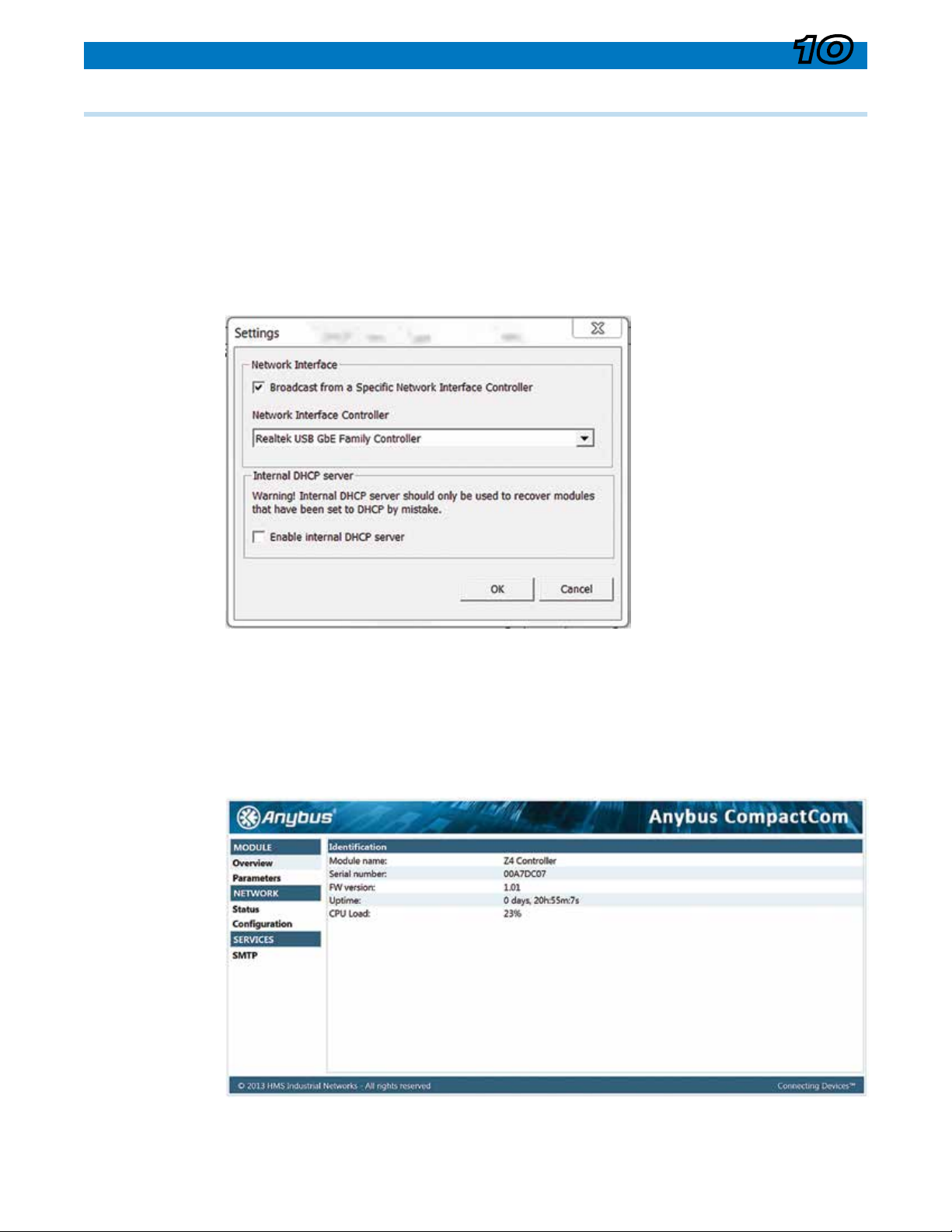
10.2 Ethernet (option)
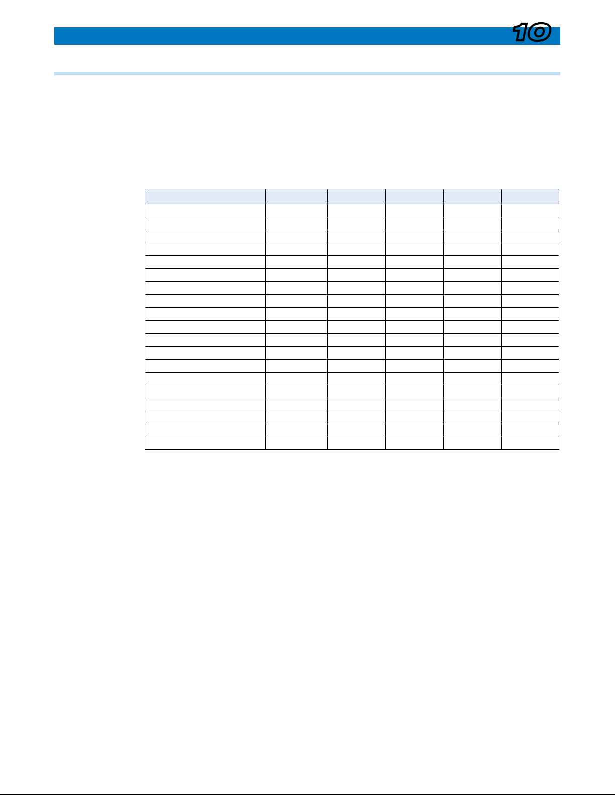
System Signals Mapping
Menu Accessible Signals
Parameter Read/Write Related Menu Entry
RunMode R Run Mode
CtrlType R \ Setup Menu \ Cong Menu \ Ctrl Type
CtrlSubType R \ Setup Menu \ Cong Menu \ RWD Type or
\ Setup Menu \ Cong Menu \ NIP Type
Diameter R \ Status Menu \ Diameter
Tapered_Setpoint R \ Status Menu \ Setpoint
Taper_Begin R \ Setup Menu \ Taper Menu \ Tap Begin
Min_SP R \ Setup Menu \ Dancer Menu \ Ten Min
Splice_Lev R/W \ Setup Menu \ Splice Menu \ Spl Level
Range R \ Setup Menu \ Range Exp Menu \ Active No.
SoftStart_Redux R/W \ Setup Menu \ Start Menu \ Start Lev
Gain_Boost R/W \ Setup Menu \ Cong Menu \ Sensitivity
DI3_Mode R \ Setup Menu \ Options Menu \ DI Mode Menu \ DI-3 Mode
DI4_Mode R \ Setup Menu \ Options Menu \ DI Mode Menu \ DI-4 Mode
DI8_Mode R \ Setup Menu \ Options Menu \ DI Mode Menu \ DI-8 Mode
PID_Gain_Level R/W \ Setup Menu \ PID Menu \ Sys Gain
PID_P-Level R/W \ Setup Menu \ PID Menu \ P Level
PID_I-Time R/W \ Setup Menu \ PID Menu \ I Level
PID_D-Level R/W \ Setup Menu \ PID Menu \ D Level
Gain_Exp R/W \ Setup Menu \ Gain Menu \ Gain Slope
Gain_Max R/W \ Setup Menu \ Gain Menu \ Gain Max
Gain_Min R/W \ Setup Menu \ Gain Menu \Gain Min
Gain_Level R \ Setup Menu \ Gain Menu \ Gain Level
AuxIn1_Value R \ Status Menu \ Aux1 Out
AuxIn2_Value R \ Status Menu \ Aux2 Out
SpdTrim_Out R \ Setup Menu \ Regulator Menu \ Trim Menu \ Trm Level
Internal System Signals
Parameter Read/Write Menu Entry
Setpoint R Internal Un-Tapered Setpoint (system setpoint before taper calculation)
Digital Alarm Signals
Documentation Name Alarm Condition
Alm_WebBreak Web break detected (typically drop in tension)
Alm_Diameter Diameter has passed through specied limit
Alm_LowTension Tension is below pre-dened limit
Alm_HighTension Tension is above pre-dened limit
Alm_Linespeed Linespeed is above specied limit
Motor_Active Signaled when Z4 is on control of motor and shaft is turning