Arjo Opera Installation guide

Operating and Product Care
Instructions
TM
KKX 52180.GB/2
Aug 2000
KPX 01700.US
Issue 1
Jan. 2001
Opera

2
The vertical and horizontal lines printed in the
margins adjacent to the text/illustrations in these
instructions are for ARJO use only and should be
disregarded by the reader.
Some of the information contained in these
instructions may become outdated, due to
improvements made to the product in the future. If
you have any questions regarding these instructions
or your lift, please contact ARJO.
The policy of ARJO is one of continuous
development, and therefore reserve the right to
change specifications without notice.
ARJO strongly advise and warn that only ARJO
Company Designated Parts, which are designed for
the purpose, should be used on equipment and
other appliances supplied by ARJO, to avoid
injuries attributable to the use of inadequate parts.
The ARJO Company’s Conditions of sale make
specific provision confirming no liability in such
circumstances.
”Opera”, “Flites” and “Lock and Load” are
trademarks of the ARJO Group

3
SECTION Page
No.
Foreword ..................................................... 4
Safety Instructions...................................... 5
Product description/function..................... 6-12
Parts referred to in this manual ................. 6-7
Slings......................................................... 8-9
Control Handset......................................... 10
Dual Control panel .................................... 10
Emergency stop button (red) ..................... 10
Reset button (green) .................................. 10
System failure lower override ................... 11
System failure wind down function .......... 11
System cut-out switch ............................... 11
Automatic cut-out ...................................... 12
Automatic stop function ............................ 12
Battery discharge indicator........................ 12
Service indicator........................................ 12
Adjustable width chassis legs.................... 12
Chassis castor Brakes ................................ 12
Using the Opera ........................................... 13-28
Before apparoaching the patient................ 13
Powered opening “V” chassis ................... 13
“Lock and Load” system jib...................... 13
Using the 4-point spreader bar .................. 13
To lift from a chair................................. 14
To lift from a bed................................... 15
To lift from the floor.............................. 17
At the toilet ............................................ 18
Powered patient positioning spreader bar
(if fitted) .................................................... 19
Using the 2-point spreader bar .................. 21
To lift from a chair................................. 21
To lift from a bed................................... 22
Using the soft stretcher.............................. 23
Using the strap stretcher ............................ 25
Patient Scale (if fitted) ............................... 28
Lift Battery Charging................................ 29-30
Warnings for Charging.............................. 29
General Safety Practises for Batteries ....... 29
Care of the Opera ........................................ 31-33
Sling Care and Cleaning............................ 31
Lift Care and Cleaning .............................. 31
Periodic Testing......................................... 32
Service Advice .......................................... 32
Labels........................................................... 34
Technical Specification............................... 35-36
Lift Dimensions......................................... 37
Contents

4
Thank you for purchasing ARJO equipment
The Opera is part of a series of quality products
designed especially for hospitals, nursing homes
and other healthcare uses.
We are dedicated to serving your needs and
providing the best products available, along with
training that will bring your staff maximum benefit
from every ARJO product.
Please contact us if you have any questions about
the operation or maintenance of your ARJO
equipment.
The touch panel label on the dual control panel
displays several instruction symbols. The letter (i)
shown on the open book icon indicates
“information”, and is an instruction to always read
the operating instructions before use (see Fig. 1).
The expected operational life of the Opera is 10
years, provided that it has been regularly serviced
and maintained as recommended in these
instructions.
The expected operational life of the consumable
parts, i.e. batteries, slings etc., is dependent on
usage (also, see the section titled “Care of the
Opera”).
All references to the patient in these instructions
refer to the person being lifted, and references to the
attendant refer to the person who operates the lift.
References to the left and right of the lift in these
instructions are as viewed when you are standing at
the rear of the Opera, facing forward, i.e. when
viewed from the dual control panel (see Fig. 1).
The lifting operations in these instructions are
described as if you are lifting a patient from a chair.
The same operations can be performed effectively
when lifting a patient from a wheelchair or a sitting
position on a bed, although a second attendant
should support the patient if the patient lacks sitting
balance.
All operations in these instructions are described as
if the attendant were using the control handset.
Each operation described can be controlled using
the control handset and/or the dual switch panel,
located at the rear of the mast.
Foreword

5
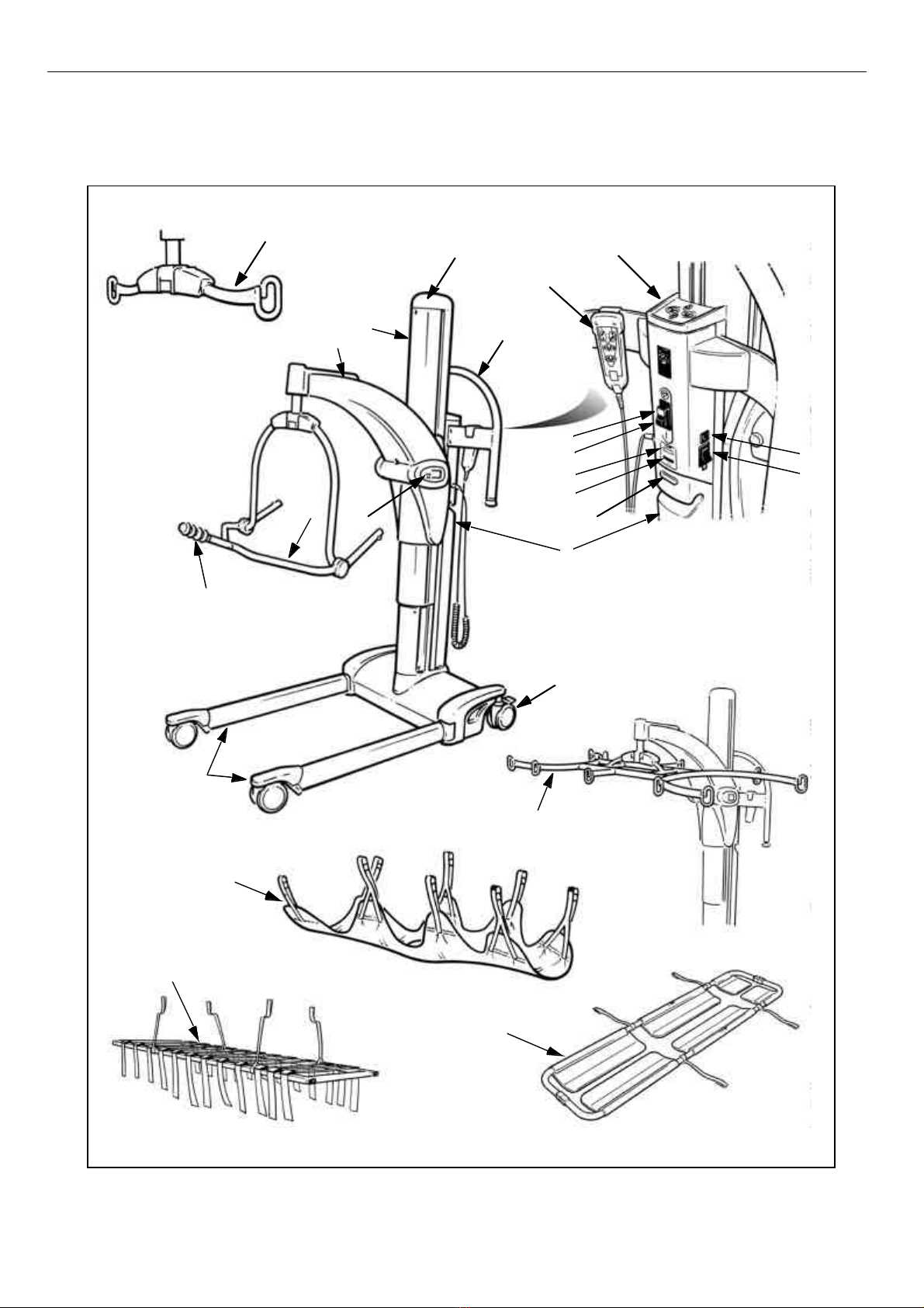
Before using the Opera, familiarize yourself with
the various parts and controls, as illustrated in Fig.
1 and other illustrations. Then please read this
entire manual thoroughly before using the Opera.
The information in the manual is crucial to the
proper operation and maintenance of the
equipment, and will help protect your product and
ensure that the equipment performs to your
satisfaction. Some of the information in this
booklet is important for your safety and must be
read and understood to help prevent possible injury.
If there is anything in the manual that is confusing
or difficult to understand, please call ARJO (the
telephone number appears on the last page of this
manual).
Symbols used adjacent to the text in these
instructions:
This product has been designed and manufactured
to provide you with trouble free use. However, this
product does contain components that, with regular
use, are subject to wear.
Also, see the section titled “Care of the Opera”. This product is intended to be operated entirely by
an attendant. No functions regarding the control of
this product should be performed by the patient. A
second attendant may be required with certain
patients.
Danger: Electrical hazard warning.
Failure to understand and obey this
warning may result in electrical shock.
Warning: Failure to understand and
obey this warning may result in injury to
you or to others.
Caution: Failure to follow these
instructions may cause damage to one or
all parts of the system or equipment.
•Note: This information is important for
the correct use of this system or
equipment.
Warning: SOME OF THESE PARTS
ARE CRITICAL TO ENSURE THE
SAFETY IN OPERATING THE OPERA
AND MUST BE EXAMINED AND
SERVICED ON A REGULAR BASIS
AND REPLACED AS NEEDED.
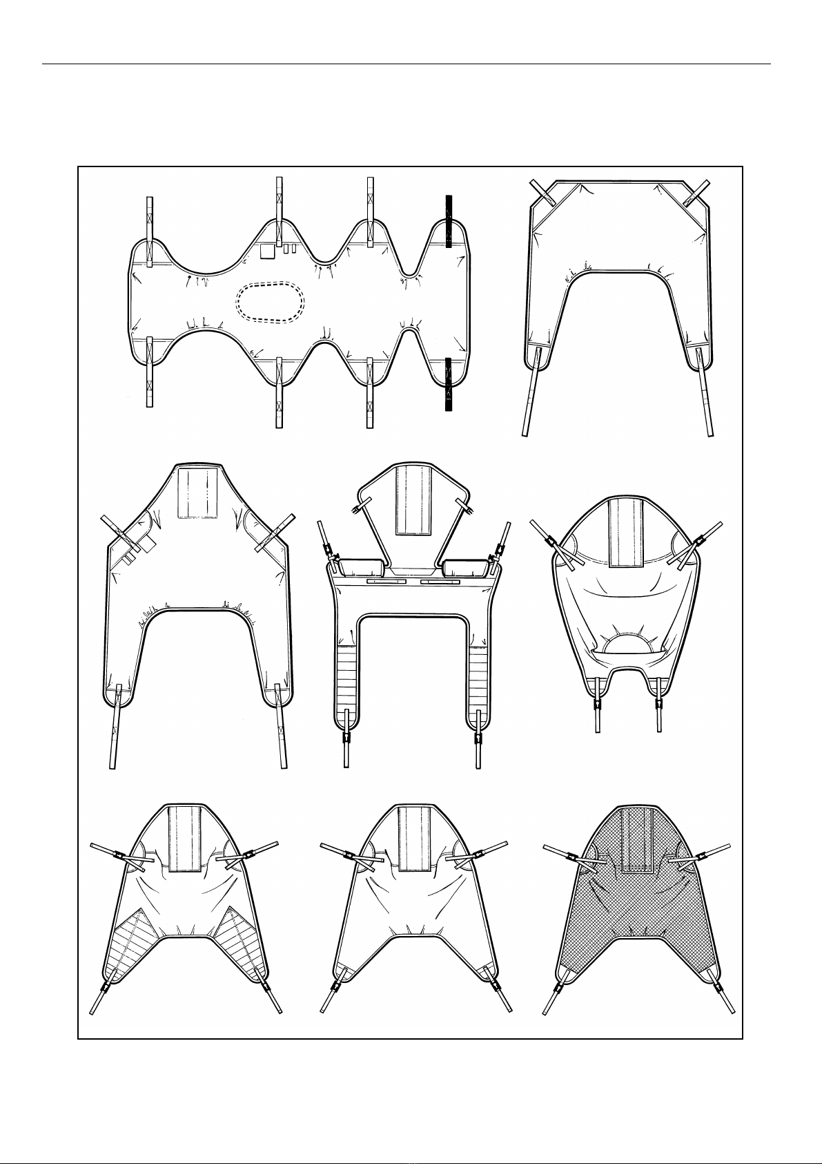
Warning : Use only ARJO slings and
stretchers that have been specifically
designed for the Opera.
Warning : Do not load theOpera beyond
the approved lifting capacity of the lowest
rated attachment/accessory.
The Opera may be used on gentle slopes
with caution.
Care should be taken when manually
lifting alternative/optional components,
i.e. stretcher frames, spreader bars etc., to
avoid injury.
Do not attempt to manually lift the
complete lift.
Caution: Although manufactured to a
high standard the Opera and accessories
should not be left for extended periods in
humid or wet areas.
Do not, under any circumstances, spray
the Opera or accessories with water, i.e.
under the shower (this excludes slings or
ARJO approved wet environment
equipment).
Warning: It is advisable to familiarize
yourself with and understand the
operation of the various controls and
features of the Opera and ensure that any
action or check specified is carried out
before lifting a patient.
Warning: The Opera has been designed
as a mobile lift for raising and
transporting patients in hospitals and care
facility environments, and should only be
used for this purpose.
The Opera can be supplied with a variety
of optional attachments, which may not be
described in these instructions. If the
Opera has been fitted with an alternative/
optional sub-assembly, i.e. a stretcher,
etc., always refer to the separate relevant
operating instructions supplement, as well
as these instructions, before operating the
lift.
Safety Instructions

6
Fig. 1
1
2
3
4
5
6
7
8
9
10
11
12
13
14
15
16
17
18
20
19
21
22
23
24
P138 9ab, P1 391 c, P119 8a, P 13 91c, P 13 95e, P1 396 c, mP 11 42c
Product Description/Function
Parts referred to in this manual

7
Fig. 1 Key
1. Mast
2. Adjustable chassis legs
3. Braked castors
4. Lift maneuvring handle
5. Jib
6. Mast top cover
7. 4-Point spreader bar
8. 2-Point spreader bar (if supplied)
9. Patient positioning handle
10. Lift battery pack
11. Battery release button
12. Patient scale (if fitted)
13. Control handset
14. Dual control panel
15. Emergency stop button
16. Reset button
17. System failure lower override
18. System cut-out switch
19. Battery discharge indicator
20. Service indicator
21. Stretcher frame (if supplied)
22. Soft stretcher (if supplied)
23. Strap stretcher (if supplied)
24. Scoop stretcher (if supplied)
Product Description/Function

8
Slings
A circular label is fitted to the lift jib for quick
color-to-size reference (see the section titled
“Labels”).
A range of special purpose slings is available as
accessories. For these or for special size slings,
contact your ARJO representative.
•Note : All Opera slings will support
420lbs. Note: the extra extra large sling
will support 440 lbs. All slings are coded
for size with a different colored edge
binding as follows:
Brown - Extra small - XS
Red - Small - S
Yellow - Medium - M
Green - Large - L
Blue - Extra Large - XL
White - Extra Extra Large - XXL
Warning : Only use ARJO supplied
slings and stretchers that are designed to
be used with the Opera. The sling profiles
illustrated (see Fig. 2) will help to identify
the various ARJO slings and fabric
stretchers available.
If Flites from ARJO (disposable slings)
are to be used with the Opera, always
refer to the separate operating instructions
for Flites (literature reference part No.
MAX01720), as well as these
instructions, before using them.
Warning: ARJO slings with head support
have two pockets at the head section
which should contain plastic rein-
forcement pieces during use. Always
ensure that these reinforcement pieces
have been inserted into the sling pockets
before using the sling.
Product Description/Function

9
4-point unpadded
sling
4-point padded sling 4-point mesh sling
4-point amputee slingLoop sling (with headrest) 4-point toileting sling
(with headrest)
Loop sling
Soft stretcher
Fig. 2
P13 90, P1 143 a, b, P9 53 a, b , c, d , e
Product Description/Function
ARJO standard sling profiles that can be used with the Opera

10
Controls and Features
Control Handset (see Fig. 3): To raise and lower
the jib and to open and close the chassis legs, press
the appropriate button on the control handset. Note:
icons with direction arrows are printed on each
button for quick reference.
If the pressure is released during any function,
powered motion will cease immediately. Do not
drop the handset into water, i.e. the bath, etc.,
although if this does happen, no harm will come to
the patient or attendant.
When it is not in use, keep the handset conveniently
ready for use by hooking it over the handle support
at the rear of the mast.
Dual Control Panel (see Fig. 4): An additional
feature fitted to the Opera is a mast mounted dual
switch panel. This operates in parallel with the
control handset to enable powered operations to be
controlled from the lift mast, as well as remotely by
using the handset. As with the handset, icons with
direction arrows are printed on each button for
quick reference.
Emergency Stop Button (Red) (see Fig. 5): If, in
an emergency, you have to immediately stop any
powered movement (other than by releasing
pressure on the control handset button or dual
switch panel button), press the “emergency stop
button” located on the rear of the mast.
Once the emergency stop button has been pressed,
the green reset button will have to be re-engaged.
This is done by pressing it in before any powered
movement can be utilized.
Reset button (green) (see Fig. 5): This is adjacent
to the emergency stop button. It is used to reset the
“power on” status after the emergency stop button
has been pressed. It is also used to reset if the
automatic overload fuse has engaged, which is
indicated by the reset button projecting outward
slightly. If the fuse has engaged and, once reset,
engages again, do not use the lift and contact the
ARJO Service Department.
P139 6a
Fig. 3
“Raise”
Button “Lower”
Button
Chassis leg
open Button
Chassis leg
close Button
Fig. 4
P1 396 b
“Raise”
Button
“Lower”
Button
Chassis leg
open Button Chassis leg
close Button
Fig. 5
P13 89b
Emergency
Stop
Reset
System
Failure
Lower
Override
System
cut-out
switch
Battery
discharge
indicator
Service
indicator
Product Description/Function

11
System Failure Lower Override (see Fig. 5): This
can be used in the event of main control failure. If
the control handset or dual switch panel fail to
operate the lift, with a patient still supported by the
sling or stretcher, a provision for lowering has been
made using the “System Failure Lower Override
switch” located to the right of the controls console.
A green and white identification label is positioned
near the switch for quick and easy recognition. If
pressure is released from the switch during use,
lowering will stop.
System Failure Wind Down Facility (see Figs. 6
& 7): If the electrical power fails due to battery
power loss or another electrical malfunction, the jib
can be lowered. To do this, first remove the
battery pack. Then use a coin or screwdriver to
slacken and remove the screw that retains the mast
top cover. Slightly lift the rear side of the top cover
approximately 3/16 inch and slide the cover
forward. Then lift it off the mast. Identify and
remove the hexagonal wrench located inside the
mast. Use the wrench to slacken the shaft lockscrew
located at the top front of the mast (see Fig. 7c) and
turn it three full turns anti-clockwise. Identify the
hexagonal hole in the shaft center inside the mast
(see Fig. 7d) and use the wrench to turn the shaft
clockwise and lower the patient.
Hold the hexagonal wrench securely in the shaft.
Do not release hand contact with the wrench as this
could result in loss of control during the lowering
procedure.
Once the patient has been lowered and removed
from the lift, ensure that the components are re-
assembled by reversing the above procedure.
If the system failure lower override switch or wind
down facility has to be operated, do not use the lift
and contact the ARJO Service Department.
System Cut-Out Switch (see Fig. 5): If the lift
functions fail to operate when the buttons on the
control handset or dual switch panel are pressed.
Check that the “green” reset button is pressed in
and that the battery pack is fully charged. If the lift
still fails to operate, check the system cut-out
switch, located to the right of the controls console
above the lower override switch. If the cut-out has
engaged, the switch will protrude from its mount.
Press the switch in to reset it.
Warning: The Lower Override switch
will only engage while the green reset
button is in. Only use this switch in an
emergency. Do not use it for normal
lowering.
Fig. 6
P13 98a, b
AB
Top
Cover Wrench
Screwdriver/Coin
•Note: One full clockwise rotation of the
shaft lowers the mast jib by 3/8 inch.
Fig. 7
P139 8c, d
C D
Shaft
lockscrew
Shaft
Warning: If the mast is in a high position
and the wind-down facility has to be used,
always ensure that suitable and safe
measures are taken to gain access to the top
cover.
•Note: To enable the shaft lockscrew to be
tightened by three full turns, the shaft
may have to be rotated slightly to make
alignment possible. To achieve this,
identify the alignment mark on the top of
the shaft and then rotate the shaft until
the mark aligns with the axis of the
lockscrew.
Product Description/Function

12
Automatic cut out (not an operator control but a
function built into the lift electronics):
If the lift is overloaded (by lifting a patient heavier
than permitted), an automatic “cut-out” engages to
prevent the lift lifting a load in excess of one and a
half times the maximum rated load. This will stop
the lift motion automatically.
If this occurs, when pressure is released from the
lift button on the handset or dual control the
electronics will, after a short delay, reset and enable
the patient to be lowered only, when either of the
“lower” buttons is pressed. Remove the patient
from the lift.
Automatic stop function (not an operator control
but a function built into the lift electronics):
Great care should be taken not to lower the spreader
bar or stretcher on to the patient or any other
obstruction. If this should happen, the motor will
stop and downward movement will be held by the
obstruction. If this occurs, immediately release the
pressure from the “lower” button, operate the
“raise” button until the spreader bar/stretcher is
clear, then remove the obstruction.
Battery Discharge Indicator(see Fig. 5): This is a
small LED display which shows the charge
condition of the lift battery (also, see the section
titled “Battery Charging” for a complete
description).
Service Indicator(see Fig. 5): This is a small LCD
display which shows the total duration of powered
operation (in hours) of the lifting and lowering
procedure. This is primarily intended to assist
service engineers.
Adjustable width chassis legs (see Fig. 8): Press
the appropriate button on either the control handset
or the dual control panel on the lift to open the
chassis legs to any variable width. When pressure is
released from the button, the movement will stop
and the chassis legs will remain securely in
position. Always transport the chassis legs in the
narrow (closed) position.
Chassis castor Brakes (see Fig. 9): The chassis
rear castors have brakes which can be foot operated
if required, i.e. when leaving the patient
unattended, or to keep the Opera in position.
Jib and spreader bars/stretcher frame (see Fig. 1):
If the Opera has not been supplied with a
“dedicated” or permanently attached powered
patient positioning 4-point spreader bar (PPP), it
will be supplied with the “Lock and Load” system
jib. This jib is fitted with a carrier able to
accommodate any of the Operajib attachments, i.e.
the 2- or 4-point spreader bars, stretcher frame, etc.
(see the section titled “Using the Opera” for full
instructions on fitting or changing the attachments).
Warning: If the system cut-out switch
engages again, do not use the lift and
contact the ARJO Service Department.
Fig. 8
P1 392 b
Fig. 9
mP 133 2e, f
Product Description/Function

13
Before Approaching the Patient:
Ensure that the battery pack supplied is fully
charged before use (to charge it, see the instructions
in the section titled “Lift Battery Charging”). When
the battery pack is fully charged, remove it from the
charger unit and insert it into the battery position of
the Opera located at the rear of the mast (see Fig.
1). To do this, first locate the recess across the
bottom of the battery with the protrusion at the
bottom of the battery position. Then pivot the
battery into position until the retaining catch
engages. An electrical connection will be made
automatically.
Ensure that the green reset button (located on the
control console below the dual control panel) is
pressed in (see Fig. 5).
Ensure that a selection of sling types and sizes is
easily available for all types of lift likely to be
performed with the Opera.
The attendant should always tell the patient what
they are going to do, and have the correct size sling
ready. When possible, always approach the patient
from the front.
If required, the chassis legs may be opened to
maneuver around a chair or wheelchair.
Powered opening “V” chassis:
Select the appropriate button on the control handset
or dual switch panel and keep it pressed until the
required width is achieved. To close the legs, press
the appropriate button. The movement will stop if
the pressure is released, whether opening or
closing.
Opera “Lock and Load” System
(see Figs. 10 & 11)
If the Opera has not been supplied with a
“dedicated” or permanently attached powered
patient positioning (PPP) spreader bar, it will be
supplied with the “Lock and Load” System jib. If
you need to fit or change the attachment, i.e.
spreader bar or stretcher frame, proceed as follows:
To remove an existing attachment, hold the unit
carefully and depress the retaining catch on the
attachment yoke (see Fig. 10) to release the
attachment. Lift the yoke upward and away from
the carrier and store it carefully for future use.
Select the attachment required. Then carefully lift
the unit up and allow the recess in the yoke to fit
around the carrier shaft. Ensure that the yoke drops
down over the carrier and the retaining catch
engages (see Fig. 11). To check the locking, try to
lift the yoke without depressing the retaining catch.
Warning: To ensure the maximum
patient comfort, do not allow the patient
to hold on to the spreader bar.
Warning: When opening or closing the
legs on a powered chassis, do not allow
anyone to stand in the way of the moving
chassis legs.
Transport the Opera with the chassis legs
in the parallel (closed) position only.
Fig. 10
P1 391 a, P 143 9a, P 14 39b
Attachment
yoke
Carrier
Retaining
catch
Using the Opera

14
Using the 4-point spreader bar
Ensure that the spreader bar is securely connected
to the jib before commencing the lift (“Lock and
Load” system jib only).
To Lift from a Chair
Place the sling around the patient so that the base of
his/her spine is covered and the head support piece
is behind the head. Pull each leg piece under the
thigh so that it emerges on the inside of the thigh
(see Fig. 12).
Ensure that the positioning handle on the spreader
bar is facing away from the patient, and that the
wide part of the spreader bar is located at the
patient’s shoulder level (see Fig. 13).
Ensure that the Opera is close enough to be able to
attach the shoulder clips of the sling to the spreader
bar. To acheive this you may have to put the
patient’s feet on or over the chassis.
Once the Opera is in position, attach the shoulder
strap attachment clips to the pegs on the spreader
bar (see Fig. 14).
Press down on the positioning handle of the
spreader bar and attach the leg strap attachment
clips to it (see Fig. 15).
Fig. 11
P1 391 b
Warning: Care must be taken when the
weight of the unit comes away from the
jib.
For larger attachments, or if you are in
doubt about being able to lift and hold the
attachment securely, use more than one
person for the operation, or support the
attachment on a bed or chair.
Fig. 12
P1 146 a,b
Fig. 13
P139 2c
•Note: The chassis rear castors have
brakes which can be foot operated when
required (see Fig. 9). Do not apply the
castor brakes at this stage, as the position
of the patient will adjust to his/her own
center of gravity when lifted.
Fig. 14
P13 92d , P100 2a,b, c
Warning: Apply the castor brakes when
leaving the patient unattended or to keep
the Opera in position on a sloping surface.
Using the Opera

15
If necessary, use the handset control to lower the
spreader bar, being careful not to lower it on to the
patient. If this should happen, there is a built-in cut-
out device which will prevent any further
downward movement. Do not continue to press the
handset lowering button.
Raise the patient by operating the handset control.
Move the lift away from the chairm, then carefully
lift the positioning handle until the patient is
reclined in the sling - the head support will now
come into use (see Fig. 16). This is the most
comfortable position for transportation, as it
reduces pressure on the patient’s thighs. The angle
of recline can be adjusted for increased comfort if
the patient is restless.
Before transportation, turn the patient to face the
attendant at approximately normal chair height (see
Fig. 17). This gives confidence and dignity and also
improves the mobility of the Opera.
Remember to release the brakes, if they have been
applied, before attempting to transport the patient.
When lowering the patient back into a chair or
when transferring from bed to chair, push down on
the positioning handle to place the patient in a
comfortable sitting position. This avoids further
lifting strain. Take care not to push down too
quickly, as this may jerk the patient’s head forward.
Fig. 15
P139 2e
•Note : If the handset button is released
during lifting or lowering, powered
motion will stop immediately.
Warning: IMPORTANT: Always check
that the sling attachment clips are fully in
position before and during the lifting
cycle, and in tension as the patient’s
weight is gradually taken up.
Fig. 16
P1 393 f
Fig. 17
P1 393 d
Warning: When lowering the lift, ensure
that the patient’s or attendant’s legs and
feet are clear of the moving mast.
Using the Opera

16
To Lift from a Bed
Before lifting a patient from a bed, ensure that there
is sufficient clearance underneath, to accommodate
for the Opera chassis legs.
To position the patient on the sling, roll the patient
toward you. Then fold the sling in half and place it
behind the patient’s back (see Fig. 18). Position the
sling carefully so that when rolled back, the patient
will lie centrally on the sling (see Fig. 19). Check
that the head support area of the sling covers the
patient’s neck.
Alternatively, the patient can be brought into a
sitting position. This is detailed in the section titled
“To Lift From A Chair”.
Approach the bed with the open side of the spreader
bar toward the patient’s head (see Fig. 20).
Use the adjustable width chassis to make
adjustments to chassis leg widths to assist
maneuvrability around obstructions, i.e. bed legs.
Position the Opera so that the spreader bar is just
above, and centrally situated over the patient.
Use the positioning handle to tilt the spreader bar
until the shoulder attachment points can be
connected to the sling shoulder strap attachment
clips (see Fig. 21).
Press down on the positioning handle until
connection of the sling leg pieces is possible (see
Fig. 22). The leg pieces must be brought under the
thighs to connect up. This may involve lifting one
leg at a time to connect. The spreader bar may need
to be lowered, using the handset control.
Fig. 18
P11 33b
Fig. 19
P10 22a
•Note : When rolling the patient back onto
the sling, roll the patient slightly in the
opposite direction so that the folded part
of the sling can be brought out.
Fig. 20
P139 3e
Warning: Care must be taken not to
lower the spreader bar on to the patient.
Fig. 21
P139 5a, P100 2 a,b ,c
Using the Opera

17
When lifting from the bed, some attendants prefer
to connect the leg pieces first. This particularly
applies to patients with large thighs. In this case,
raise the hip and knee into maximum flexion and
attach the leg strap attachment clips. Then tilt the
spreader bar toward the shoulders for connection.
Lift the patient using the handset control, and adjust
the patient to a comfortable position for transfer
(see Fig. 23). The specially designed sling together
with its integral head support, enables one person to
carry out the complete lifting function without
additional help.
If returning the patient to a bed, adjust the sling
position as necessary to move the patient into the
desired position above the bed, then lower the
patient using the handset control.
Move the Opera away before removing the sling
from under the patient. If transferring the patient to
a chair, refer to the section titled “To Lift from a
Chair”.
To Raise from the Floor
Put the sling around the patient, by using the rolling
or sitting-up method. Depending on the
circumstances, space and/or position of the patient,
approach the patient with the open part of the
chassis. Open the chassis legs if necessary, and lift
the patient’s legs over the chassis as shown in Fig.
24.
The patient’s head and shoulders could be raised on
pillows for comfort, if required, but this is not
essential when connecting the sling to the spreader
bar.
With the open part of the spreader bar pointing
down toward the shoulders, attach the shoulder
strap attachment clips as shown in Fig. 25 and inset.
Fig. 22
P1 395 b
Warning: IMPORTANT: Always check
that the sling attachment clips are fully in
position before and during the lifting
cycle, and in tension as the patient’s
weight is gradually taken up.
Fig. 23
P1 395 d
Warning: When lowering the lift, ensure
that the patient’s or attendant’s legs and
feet are clear of the moving mast.
Only when the patient’s body weight is
fully supported by the bed may the sling
leg connection clips be detached,
followed by the shoulder connections.
Fig. 24
P13 94a
Using the Opera

18
Once connected, raise the hip and knee into
maximum flexion, and push down on the
positioning handle in order to connect the leg strap
attachment clips as shown in Fig. 26. This will raise
the patient’s head and shoulders slightly.
When lifting from the floor, some attendants prefer
to connect the leg pieces first. This particularly
applies to patients with large thighs. In this case,
raise the hip and knee into maximum flexion, and
attach the leg straps first. Then tilt the spreader bar
toward the shoulders to enable the shoulder straps
to be connected.
When all the straps have been properly connected,
raise the patient from the floor in a semi-recumbent
position. Support the head to offer comfort and
reassurance to the patient. Once raised from the
floor, ensure that the patient’s legs are clear of the
chassis before continuing to lift (see Fig. 27). The
leg sections of the sling will tend to be fairly high
in the crotch, so straighten them out for added
comfort. The patient may be positioned in a chair,
or placed on a bed. If the patient is prone to extensor
spasm, he/she may be lifted by the Opera, but
special attention should be paid to support of the
legs during the early part of the lift.
When lifting a patient with leg amputations, use the
double amputee sling (available as an accessory
from ARJO). This sling is specially designed to
accommodate for the differing patient center of
gravity.
At the Toilet
To toilet a patient, use the toilet sling with head rest.
The toilet sling is fitted in a similar manner to the
standard 4-point sling, except that the sling is not
taken to the base of the patient’s spine but fitted so
that the top of the head support piece of the sling is
level with the top of the patient’s head (see Fig. 28),
as a guide to positioning.
Fig. 25
P139 4b, P1 002 a, b,c
Fig. 26
P139 4c
Warning: IMPORTANT: Always check
that the sling attachment clips are fully in
position before and during the lifting
cycle, and in tension as the patient’s
weight is gradually taken up.
Fig. 27
P1 394 d
Warning: When lowering the lift ensure
that the patient’s or attendant’s legs and
feet are clear of the moving mast.
Transportation of a patient should always
be done with the chassis legs parallel
(closed) as this will make maneuvrability
easier, especially through doorways. The
patient should be positioned facing the
attendant (see Fig. 17). Apply the chassis
brakes if leaving the patient unattended.
Using the Opera

19
The ARJO toilet sling has been specially designed
to help support patients while toileting.
To provide the best possible access when toileting,
the sling has a wide commode opening and because
of this it is essential that:
(a) the correct size sling is chosen, relative to the
weight and height of the patient; and
(b) both of the patient’s arms are positioned
outside the sling, over the padded areas but
under the “head section” support straps (see
Fig. 28). This will help to prevent the patient
from sliding through the sling.
When used in accordance with these instructions,
the toileting sling provides a very effective method
of toileting dependent patients.
Once the patient has been lifted and transported to
the toilet, position the lift so that the patient is
positioned above the toilet seat.
Apply the chassis brakes.
Unbutton and/or remove the patient’s garments and
lower the patient to a comfortable sitting position.
Powered Patient Positioning
Spreader Bar (if fitted)
If the lift has been fitted with a Powered Patient
Positioning (PPP) spreader bar, use this type of
spreader bar (including sling positioning with
patient, sling connection to the spreader bar, and
patient handling) as you would the non-powered 4-
point spreader bar described previously in these
instructions.
The fundamental difference is that the PPP spreader
bar has the added advantage of enabling the patient
positioning maneuvre to be performed by the
attendant with minimal physical strain.
Fig. 28
P113 0a
“Head Section”
support strap buckles
Warning: It is essential to familiarize
yourself with the correct method of use
before any attempt is made to lift a
patient.
Always ensure that the patient has
sufficient trunk and head control to be
safely lifted in the toilet sling. If in doubt,
use the standard type sling.
•Note: It is advisable to release the “head
section” support strap buckles before
fitting the sling. Once the sling is around
the patient, reconnect the support strap
buckles, while ensuring that the patient’s
arms are positioned over the sling.
Warning: Always ensure that the patient,
when suspended, is in an upright sitting
position as shown in Fig. 28.
Warning: When lowering the lift, ensure
that the patient’s or attendant’s legs and
feet are clear of the moving mast.
Warning: Always use the toilet sling with
caution. Encourage the patient to hold
tightly to the sling to avoid sliding out. Do
not use the toilet sling for lifting and
transportation apart from toilet visits.
Fig. 29
P139 7a
Jib
Motor
cover
Gearbox
covers
Support
frame
Sling attachment lugs
Isolator
/cut-off
switch
Positioning
control handle
Spreader
bar
Using the Opera

20
Rotate the PPP spreader bar manually and in the
same way as the manual patient positioning
spreader bar.
The PPP spreader bar is fully waterproof and is
classified by ARJO as a wet environment unit. It
has a blue and white circular label attached to it to
qualify this (see the section titled “Labels”). The
label signifies that the lower end of the unit may be
immersed in bath water.
To operate the powered patient positioning
function, ensure that the isolator/cut off switch is in
the on position (see Fig. 30).
When you are ready to perform the patient
positioning function (as described previously), hold
the positioning handle and apply a lifting or
lowering action as necessary (see Fig. 31).
Powered movement will continue in the direction
of hand pressure until the limit of travel has been
reached or until pressure is released from the
handle.
The spreader bar will remain firmly in position
once powered movement has ceased.
Warning: Before using the lift when it is
fitted with the PPP spreader bar,
familiarize yourself with the various parts
as illustrated in Fig. 29. Then read and
thoroughly understand the following
operating instructions.
The PPP spreader bar must be used in
accordance with the following
instructions and in conjunction with the
operating instructions previously
described for the manually operated (non-
powered) 4-point spreader bar.
The lifting capacity of the lift when fitted
with the PPP spreader bar remains the
same as that of the non-powered patient
positioning spreader bar version.
Fig. 30
P1 389 d
Off
On
Fig. 31
P1 397 b
•Note: A slight pivoting movement of the
handle may be noticed. This is correct,
and is how the direction sensing device
operates.
Warning: To stop any powered move-
ment, release the pressure from the handle
or press the isolator/cut-off switch.
•Note: The isolator/cut-off switch can
remain in the ON position indefinitely if
required. It will not drain any power from
the battery.
Warning: Before and during operation of
the powered patient positioning spreader
bar, ensure that all obstructions are clear
of the spreader bar, support frame and jib.
Using the Opera
Other manuals for Opera
1
Table of contents
Other Arjo Medical Equipment manuals

Arjo
Arjo Dual-Loop Attachment Straps User manual

Arjo
Arjo Typhoon User manual

Arjo
Arjo SARA Combilizer User manual

Arjo
Arjo Flowtron ACS900 User manual

Arjo
Arjo MaxiSlide User manual

Arjo
Arjo Pentalex Plus User manual

Arjo
Arjo Enterprise ENT-ACC06 User manual

Arjo
Arjo Prioma User manual

Arjo
Arjo Maxi Air User manual

Arjo
Arjo Maxi Sky 1000 User manual

Arjo
Arjo Carevo Operating instructions

Arjo
Arjo Huntleigh Sonicaid Team3 USA User manual

Arjo
Arjo Miranti User manual

Arjo
Arjo TheraKair Visio User manual

Arjo
Arjo Maxi Sky 2 User manual

Arjo
Arjo Miranti User manual

Arjo
Arjo Flowtron Excel User manual

Arjo
Arjo CARENDO User manual

Arjo
Arjo Parker User manual

Arjo
Arjo Ninjo User manual