manuals.online logo
Brands
  1. Home
  2. •
  3. Brands
  4. •
  5. Siemens
  6. •
  7. Control Unit
  8. •
  9. Siemens 3UF51 User manual

Siemens 3UF51 User manual

GWA 4NEB 631 5286-30a 1
¿
Á
Â
Ã
Ä
4,9
85
100
70
50
125
5
20 21 22 23 24 25 26 27 28
.5 .6 .7 .8
.4.3
.2
1
OUT
32 33 34 35 PE
Sys.
3UF5
30 31
1.2 .3 .4
IN
< 300V AC/DC
EN 50022
35 mm
Sys.
3UF5
À
Eine sichere Gerätefunktion ist nur mit zertifizierten
Komponenten gewährleistet!
Verbindungskabel nicht unter Spannung stecken oder
ziehen !
Beachten Sie das Systemhandbuch 3UF5.
Bild
¿SUB-D-Buchse zum Grundgerät 3UF50
ÀSUB-D-Buchse zum Bedienbaustein 3UF52 oder
PC
Á8 extern versorgte Eingänge DC 24 V, AC 115 V,
AC 230 V, je nach Ausführung
Â4 Relaisausgänge
ÃPE-Anschluss
ÄBefestigungswinkel
Anschlussquerschnitte
- ein- und mehrdrähtig 1 x (0,5 bis 4,0) mm2
2 x (0,5 bis 2,5) mm2
- feindrähtig 1 x (0,5 bis 2,5) mm2
mit/ohne Aderendhülse 2 x (0,5 bis 1,5) mm2
Anzugsdrehmoment 0,8 bis 1,2 Nm
GEFAHR
Gefährliche Spannung.
Lebensgefahr oder Gefahr schwerer
Verletzung.
Vor Beginn der Arbeiten Anlage und
Gerät spannungsfrei schalten.
Deutsch
!
Dieses Gerät wurde im Werk sorgfältig
geprüft und in Ordnung befunden. Auf
dem Weg zu Ihnen können u. U. Bean-
spruchungen aufgetreten sein, auf die
wir keinen Einfluss haben.
Die Ausgangsrelais können sich in einem
undefinierten Schaltzustand befinden.
Im Interesse der Sicherheit empfehlen wir folgende
Maßnahme: Stellen Sie sicher, dass sich die Aus-
gangsrelais in einem definierten Schaltzustand
befinden. Legen Sie zuerst die Versorgungsspanung
für SIMOCODE-DP an.
Schalten Sie danach den Hauptstromkreis ein.
Ansonsten können angeschlossene Geräte unkon-
trolliert eingeschaltet und zerstört werden!
Reliable functioning of the equipment is only ensured
with certified components.
Do not plug in or unplug connecting cable under live
conditions!
Follow system manual 3UF5.
Figure
¿SUB-D jack to basic unit 3UF50
ÀSUB-D jack to Operator module 3UF52 or PC
Á8 externally supplied inputs 24 V DC, 115 V AC,
230 V AC, depending on version
Â4 relay outputs
ÃPE connection
ÄMounting bracket
Conductor sizes
- Solid and stranded 1 x (0.5 to 4.0) mm2
2 x (0.5 to 2.5) mm2
- Finely stranded 1 x (0.5 to 2.5) mm2
with/without end sleeve 2 x (0.5 to 1.5) mm2
Tightening torque 0.8 to 1.2 Nm/7 to 11 lb.in
DANGER
Hazardous voltage.
Will cause death or serious injury.
Disconnect power before working
on equipment.
English
!
This device has been carefully examined
and found to in be good working order at
the factory.
During shipment, it may have been
subjected to stress or other influences which we
have no control over. The output relays may be in
an undefined switching state.
For safety reasons, we recommend that you take
the following measures:
Ensure that the output relays are in a defined
switching state.
Apply the supply voltage for SIMOCODE-DP first.
Then, switch on the main electrical circuit.
If these precautions are not taken, connected
devices may be inadvertently switched on and
destroyed!
Le fonctionnement sûr de l'appareil n'est garanti
qu'avec des composants certifiés.
Le câble ne doit pas être enfiché ou déconnecté sous
tension!
Respecter le manuel de système 3UF5.
Figure
¿Embase SUB-D vers appareil de base 3UF50
ÀEmbase SUB-D vers module de commande 3UF52
ou PC
Á8 entrées à alimentation externe 24 V c.c.,
115 V c.a., 230 V c.a., selon la version
Â4 sorties de relais
ÃBornes PE
ÄEcart de fixation
Sections raccordables
- âme massive / câblée 1 x (0,5 à 4,0) mm2
2 x (0,5 à 2,5) mm2
- âme souple 1 x (0,5 à 2,5) mm2
avec/sans embouts 2 x (0,5 à 1,5) mm2
Couple de serrage 0,8 à 1,2 Nm/7 à 11 lb.in
DANGER
Tension dangereuse.
Danger de mort ou risque de
blessures graves.
Mettre hors tension avant
d’intervenir sur l’appareil.
Français
!
Cet appareil a été contrôlé minutieuse-
ment en usine et est exempt de défaut.
Sur son itinéraire vers le client, le pro-
duit peut éventuellement avoir soumis à
des contraintes, sur lesquels nous n'avons aucune
influence. Il est possible que les relais de sortie se
trouvent dans un état de commutation indéfini.
Pour des raisons de sécurité, nous recommandons
les mesures suivantes :
Assurez-vous que les relais de sortie se trouvent
dans un état de commutation défini.
Appliquez tout d'abord la tension d'alimentation
pour SIMOCODE-DP.
Activez ensuite le circuit principal .Dans tout autre
cas, les appareils connectés pourraient être activés
de manière incontrôlée et détruits!
Erweiterungsbaustein
Expansion module
Bloc d'extension
Módulo de extensión
Modulo di ampliamento
Módulo de ampliação
3UF51
Betriebsanleitung Operating Instructions Instructions de service
Instructivo Istruzioni di servizio Instruções de Serviço Bestell-Nr./Order No.: 3ZX1012-0UF51-1AA1
Vor der Installation, dem Betrieb oder der Wartung
des Geräts muss diese Anleitung gelesen und ver-
standen werden.
Read and understand these instructions before
installing, operating, or maintaining the equipment. Ne pas installer, utiliser ou entretenir cet équipement
avant d'avoir lu et assimilé ce instructions.
El funcionamiento seguro del aparato sólo está
garantizado con componentes certificados.
¡No enchufar o desenchufar el cable de conexión con
el aparato bajo tensión!
Observar el manual del sistema 3UF5.
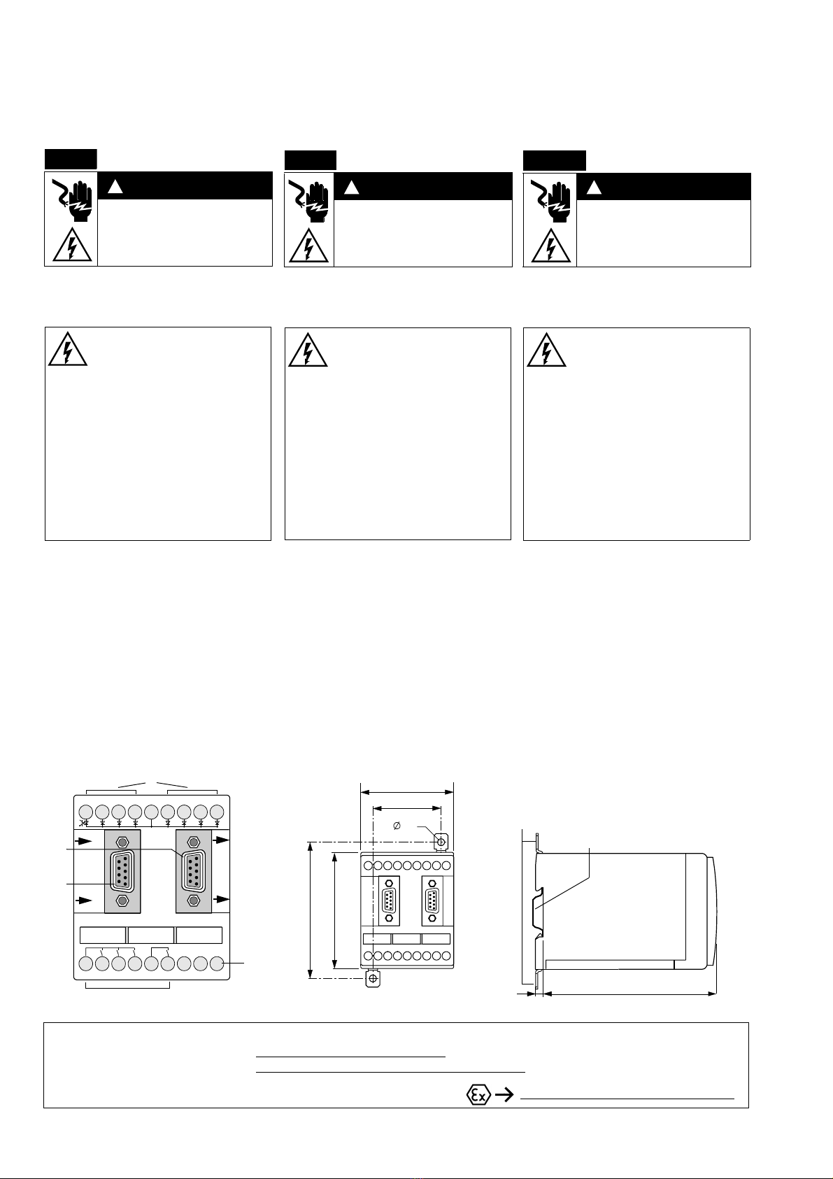
Figura
¿Conector Sub D para el 3UF50
ÀConector Sub D para el 3UF52 o PC
Á8 entradas con alimentación externa de DC 24 V,
AC 115 V ó AC 230 V
Â4 salidas de relé
ÃConexión de PE
ÄAngular de fijación
Secciones de conexión
-uno o varios hilos 1 x (0,5 a 4,0) mm2
2 x (0,5 a 2,5) mm2
- flexible 1 x (0,5 a 2,5) mm2
con/sin terminal de cable 2 x (0,5 a 1,5) mm2
Par de apriete 0,8 a 1,2 Nm
PELIGRO
Tensión peligrosa.
Puede causar la muerte o lesiones
graves.
Desconectar la alimentación eléc-
trica antes de trabajar en el equipo.
Español
!
Este aparato ha sido comprobado cuida-
dosamente antes de su expedición y
no se ha detectado ningún defecto.
Sin embargo, no se puede excluir que
durante el transporte ha sido sometido a cargas
excepcionales fuera del control del fabricante, y
es posible que los relés de salida se encuentren
en un estado de maniobra no definido.
Por lo tanto, se recomienda adoptar las siguientes
medidas de precaución:
Compruebe que los relés de salida se encuentren
en un estado de maniobra definido.
Primeramente, aplique la tensión de alimentación
del SIMOCODE-DP.
A continuación, conecte el circuito de corriente
principal.
De lo contrario, se pueden activar de forma incon-
trolada los equipos conectados. ¡Peligro de daños
materiales!
Technische Änderungen vorbehalten. Zum späteren Gebrauch aufbewahren! Bestell-Nr./Order No.: 3ZX1012-0UF51-1AA1
Subject to change without prior notice. Store for use at a later date. Printed in the Federal Republic of Germany
© Siemens AG 1996
Technical Assistance: Telephone: +49 (0) 9131-7-43833 (8°° - 17°° CET) Fax: +49 (0) 9131-7-42899
E-mail: technical-a[email protected]
Internet: www.siemens.de/lowvoltage/technical-assistance
Technical Support: Telephone: +49 (0) 180 50 50 222 www.siemens.com/lowvoltage/manuals
Il funzionamento sicuro dell'apparecchiatura viene
garantito soltanto con componenti certificati.
Non estrarre o inserire il cavo di collegamento in pre-
senza di tensione!
Attenersi al manuale di sistema 3UF5.
Figura
¿Connettore femmina SUB-D per il collegamento
con il 3UF50
ÀConnettore femmina SUB-D per il collegamento
con il modulo 3UF52 o PC
Á8 uscite alimentate esternamente DC 24 V, AC
115 V, AC 230 V, a seconda dell’esecuzione
Â4 uscite relè
ÃCollegamento in PE
ÄCerniera di fissaggio
Sezioni dei conduttori
- a filo unico e a corda rigida 1 x (0,5 ... 4,0) mm2
2 x (0,5 ... 2,5) mm2
- a filo flessibile 1 x (0,5 ... 2,5) mm2
con/senza puntalino 2 x (0,5 ... 1,5) mm2
coppa di serraggio 0,8 ... 1,2 Nm
PERICOLO
Tensione pericolosa.
Può provocare morte o lesioni gravi.
Scollegare l’alimentazione prima di
eseguire eventuali interventi
all’equipaggiamento.
Italiano
!
Questo apparecchio è stato accurata-
mente controllato in fabbrica ed è stato
trovato in ordine.
Durante il trasporto si sono potute
eventualmente verificare delle sollecitazioni sulle
quali non abbiamo nessuna influenza. I relè di
uscita possono trovarsi in uno stato collegato
indefinito.
Per motivi di sicurezza consigliamo le seguenti
misure:
assicuratevi che i relè di uscita si trovino in stato
definito.
Applicate dapprima la tensione di alimentazione
per SIMOCODE-DP.
Inserite successivamente il circuito principale.
Gli apparecchi collegati potrebbero altrimenti
essere inseriti e distrutti in modo incontrollato!
O funcionamento seguro do aparelho apenas pode
ser garantido se forem utilizados os componentes
certificados.
Não conectar ou retirar o cabo de ligação sobre
tensão !
Observe o manual do sistema 3UF5.
Figura
¿Plugue SUB-D para o dispositivo-base 3UF50
ÀPlugue SUB-D para o módulo de manejo 3UF52 ou
PC
Á8 entradas alimentadas externamente CC 24 V,
CA 115 V, CA 230 V, dependendo do modelo
Â4 saídas de relé
ÃConexão PE
ÄÂngulo de fixação
Secções transversais de conexão
- uni e multifilar 1 x (0,5 até 4,0) mm2
2 x (0,5 até 2,5) mm2
- de fio fino 1 x (0,5 até 2,5) mm2
com/sem revest.de cabo 2 x (0,5 até 1,5) mm2
Torque de aperto 0,8 até 1,2 Nm
PERIGO
Tensão perigosa.
Perigo de morte ou ferimentos
graves.
Desligue a corrente antes de
trabalhar no equipamento.
Português
!
Este aparelho foi ensaiado cuidadosa-
mente na origem e está em ordem.
Devido ao transporte pode ser que tenha
sido submetido a solicitações, sobre as
quais não temos influência alguma. É possível que
os relés de saída se encontrem num estado de
comutação indefinido.
No interesse da segurança, recomendamos a
seguinte medida:
Certifique-se de que os relés de saída se encontram
num estado de comutação definido.
Em primeiro lugar ligue a tensão de alimentação
para SIMOCODE-DP.
Em seguida ligue o circuito principal.
Em caso contrário, os aparelhos ligados podem
ligar-se de maneira descontrolada e destruir-se!
¿
Á
Â
Ã
Ä
4,9
85
100
70
50
125
5
20 21 22 23 24 25 26 27 28
.5 .6 .7 .8
.4.3
.2
1
OUT
32 33 34 35 PE
Sys.
3UF5
30 31
1.2 .3 .4
IN
< 300V AC/DC
EN 50022
35 mm
Sys.
3UF5
À
Leer y comprender este instructivo antes de la
instalación, operación o mantenimiento del equipo. Leggere con attenzione questi istruzioni prima di
installare, utilizzare o eseguire manutenzione su
questa apparecchiatura.
Ler e compreender estas instruções antes da
instalação, operação ou manutenção do
equipamento.

Other Siemens Control Unit manuals

Siemens SIMOTION D4x5 Series User manual

Siemens

Siemens SIMOTION D4x5 Series User manual

Siemens SIMATIC ET 200AL User manual

Siemens

Siemens SIMATIC ET 200AL User manual

Siemens SIRIUS 3RK3211 User manual

Siemens

Siemens SIRIUS 3RK3211 User manual

Siemens RC-30U User manual

Siemens

Siemens RC-30U User manual

Siemens SIMATIC RF170C User manual

Siemens

Siemens SIMATIC RF170C User manual

Siemens SIRIUS 3RW5 series Technical Document

Siemens

Siemens SIRIUS 3RW5 series Technical Document

Siemens ET 200S 1SI Parts list manual

Siemens

Siemens ET 200S 1SI Parts list manual

Siemens RCC-2/R User manual

Siemens

Siemens RCC-2/R User manual

Siemens Modem Block User manual

Siemens

Siemens Modem Block User manual

Siemens HLIM Service manual

Siemens

Siemens HLIM Service manual

Siemens SIMATIC S7-300 FM 350-1 User manual

Siemens

Siemens SIMATIC S7-300 FM 350-1 User manual

Siemens SINAMICS S Series User manual

Siemens

Siemens SINAMICS S Series User manual

Siemens ECOFAST 3RK1911-4AB Series User manual

Siemens

Siemens ECOFAST 3RK1911-4AB Series User manual

Siemens SIMATIC ET 200AL User manual

Siemens

Siemens SIMATIC ET 200AL User manual

Siemens SIRIUS ACT 3SU14 User manual

Siemens

Siemens SIRIUS ACT 3SU14 User manual

Siemens SINUMERIK 840D sl Owner's manual

Siemens

Siemens SINUMERIK 840D sl Owner's manual

Siemens PS-35 User manual

Siemens

Siemens PS-35 User manual

Siemens SINUMERIK 840Di Parts list manual

Siemens

Siemens SINUMERIK 840Di Parts list manual

Siemens Simatic S7-400 User manual

Siemens

Siemens Simatic S7-400 User manual

Siemens RUGGEDCOM RS900F User manual

Siemens

Siemens RUGGEDCOM RS900F User manual

Siemens Simatic 6ES7132-4HB01-0AB0 User manual

Siemens

Siemens Simatic 6ES7132-4HB01-0AB0 User manual

Siemens SIRIUS User manual

Siemens

Siemens SIRIUS User manual

Siemens SIMATIC FM 450-1 User manual

Siemens

Siemens SIMATIC FM 450-1 User manual

Siemens SINAMICS G120 User manual

Siemens

Siemens SINAMICS G120 User manual

Popular Control Unit manuals by other brands

LOGICDATA CBX-1 user manual

LOGICDATA

LOGICDATA CBX-1 user manual

Audipack 261511 manual

Audipack

Audipack 261511 manual

National Instruments NI-9244 User manual and specifications

National Instruments

National Instruments NI-9244 User manual and specifications

PMFoundations Attenuverter Assembly guide

PMFoundations

PMFoundations Attenuverter Assembly guide

Murata ABR Getting started guide

Murata

Murata ABR Getting started guide

WAREMA WMS WebControl pro manual

WAREMA

WAREMA WMS WebControl pro manual

CHENGDU VANTRON TECHNOLOGY AP6255 user manual

CHENGDU VANTRON TECHNOLOGY

CHENGDU VANTRON TECHNOLOGY AP6255 user manual

Digi XBee3 DigiMesh 2.4 Update instruction manual

Digi

Digi XBee3 DigiMesh 2.4 Update instruction manual

ASAHI 55 Installation, operation and maintenance manual

ASAHI

ASAHI 55 Installation, operation and maintenance manual

Allen-Bradley XM-124 user manual

Allen-Bradley

Allen-Bradley XM-124 user manual

SEA SWING 2 DG R2F manual

SEA

SEA SWING 2 DG R2F manual

Ansell Alphatec K72 141 100 instruction manual

Ansell

Ansell Alphatec K72 141 100 instruction manual

Richter GUT/F Series Installation and operating manual

Richter

Richter GUT/F Series Installation and operating manual

Emerson Asco PV-MXX-272/374 Series Installation and maintenance instructions

Emerson

Emerson Asco PV-MXX-272/374 Series Installation and maintenance instructions

Watts FRG3015-F RV Installation and operating manual

Watts

Watts FRG3015-F RV Installation and operating manual

C-Max CMM-9304-V2.1 manual

C-Max

C-Max CMM-9304-V2.1 manual

Giacomini R314DN manual

Giacomini

Giacomini R314DN manual

GEM 740 Installation, operating and maintenance instructions

GEM

GEM 740 Installation, operating and maintenance instructions

manuals.online logo
manuals.online logoBrands
  • About & Mission
  • Contact us
  • Privacy Policy
  • Terms and Conditions

Copyright 2025 Manuals.Online. All Rights Reserved.