FKI GL 9000 Series User manual

Users Manual
Turbomatic contact grill
GL 9000 series
Version 2.4 – SEP 2016

2

3
Content of this manual
Content of this manual .............................................................................3
1.Introduction ...............................................................................4
2.Generally ...................................................................................4
2.1.Manufacturer .......................................................................................................... 4
2.2.Machine plate ......................................................................................................... 4
Machine plate is placed in the back on the left side ........................................4
3.Overview and application .................................................................5
3.1.Generel description ................................................................................................ 5
3.2.The contact grill purpose and intended use .................................................................. 5
3.3.Warning on foreseeable misuse ............................................................................. 5
3.4.Technical specifications and consumption ............................................................. 5
3.5.Placement of the contact grill ................................................................................. 6
4.Safety and residual risks ...............................................................6
4.1.Safety precautions to be taken by the user ............................................................ 6
4.1.1.Personal safety equipment ................................................................................. 6
4.2.Residual risks ......................................................................................................... 6
5.Operation...................................................................................7
5.1.Quick-guide ............................................................................................................ 7
5.2.Programming .......................................................................................................... 7
5.3.Locking display ....................................................................................................... 8
5.4.Operating ............................................................................................................... 9
5.5.Stop ........................................................................................................................ 9
5.6.Emergency stop ..................................................................................................... 9
5.6.1.Restart efter emergency stop ............................................................................. 9
5.7.Adjustment ............................................................................................................. 9
5.8.Frying ..................................................................................................................... 9
6.Transport and installation............................................................10
6.1.Transport ...............................................................................................................10
6.2.Installation .............................................................................................................10
6.3.Demands to the installation place .........................................................................10
6.4.Connection ............................................................................................................10
7.Maintenance, fault-finding and repair .............................................11
7.1.Cleaining and order ...............................................................................................11
7.2.Preventive maintenannce ......................................................................................11
7.2.1.Fault finding .......................................................................................................12
7.3.Repair ....................................................................................................................12
7.3.1.Specifications on spare parts ............................................................................13
8.End of use ...............................................................................21
8.1.Destruction ............................................................................................................21
21
9.Annex .....................................................................................21
9.1.Labels, symbols and pictograms ...........................................................................21
9.2.EC Declaration of Conformity ................................................................................22
9.4.Wirering diagrams .................................................................................................23

4
1. Introduction
Original manual
This manual is FKI Fast Food Teknik A/S translation to the original instructions for Turbomatic
contact grill, hereinafter called the contact grill.
Purpose
The purpose of this manual is to ensure proper installation, use, handling and maintenance of con-
tact grill.
Accessibility
The instructions must be kept in a known place for staff where it is easily accessible to opera-
tors and maintenance personnel.
Knowledge
It is the employer's (owner of the contact grill) obligation to ensure that all who serve, main-
tain or repair the contact grill, read the instructions, at least those parts of it that are relevant to
their work.
Additionally, all who serve, maintain or repair the contact grill, must themselves seek information in
the instructions.
2. Generally
2.1. Manufacturer
The contact grill is manufactured by
Company name: FKI Fast Food Teknik A/S
Adress: Byghøjvej 5, Verninge
5690 Tommerup
Name of the contact grill:
The full name of the contact grill is Turbomatic GL 90xx.
2.2. Machine plate
Machine plate is placed in the back on the left side

5
3. Overview and application
3.1. Generel description
Turbomatic contact grill has been designed for simultaneous cooking on both sides, since the ma-
chine have an upper and a lower fry pan. The contact grill is made of stainless steel with an easy
to clean surface.
3.2. The contact grill purpose and intended use
The contact grill is for roasting meat with a uniform thickness, also directly from the frozen state.
3.3. Warning on foreseeable misuse
Do not use the contact grill for any purpose than frying meat products.
3.4. Technical specifications and consumption
Dimensions
GL 9001 GL 9002 GL 9003 GL 9010
Dimension W
x D x H [mm] 400 x 630 x 480 600 x 630 x 480 400 x 630 x 480 490 x 730 x 480
Weight 62 kg 85 kg 65 kg 95 kg
Note the height is set in the closed state (represented by frying). When open, an additional 200
mm space, so the maximum height is 680 mm.
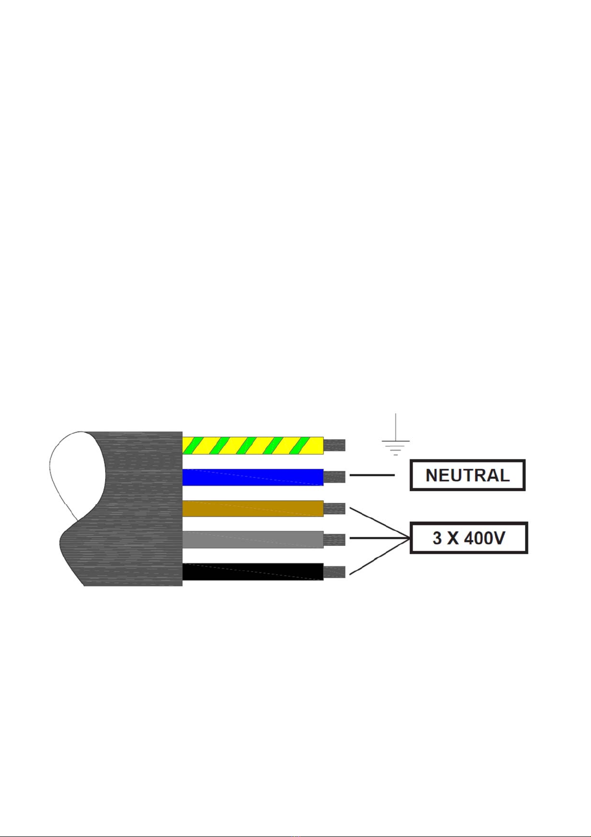
Electricity
The contact grill must be earth connected and RCD through connection socket.
Connection power: 3 x 400 V AC (3L + N + EG)
Connection frequency: 50/60 Hz
Connection
power
Absorbed
power
Absorbed
current
Min. Fuse in in-
stallation
GL 9001 400 V 8,8 kW 18,5 A 20 A
GL 9002 400 V 13,7 kW 19,2 A 20 A
GL 9003 400 V 9,8 kW 15,2 A 20 A
GL 9010 400 V 11,1 kW 16 A 16 A
Noise
Airborne noise coming from the contact grill:

6
Measured sound pressure level dB(A): < 70.
3.5. Placement of the contact grill
The contact grill must be set up on a table or the like in an appropriate working height.
Operation is done from the front of the contact grill.
For the sake of ventilation, allow free passage of air under and behind the machine.
The contact grill must be placed under hoods or other suction of cooking smells.
4. Safety and residual risks
4.1. Safety precautions to be taken by the user
4.1.1. Personal safety equipment
It is recommended to use gloves during the operation of the grill since there are several hot sur-
faces on the contact grill.
4.2. Residual risks
The surfaces, especially upper and lower fry pan, but also the housing of the upper
fry pan is very hot. Therefore take care not to touch these during operation of the
contact grill.

7
5. Operation
5.1. Quick-guide
The main switch mounted at the rear turns on the contact grill.
The contact grill will move the upper pan(s) to opened position and is
now in the Off mode. The display shows a small dot at bottom's right corner of the display,
indicating that there is power on the contact grill.
The contact grill is operated by pressing ON, and upper frying pan will close. The contact grill goes
into standby mode and begin heating to the preset standby temperature.
When this temperature is reached, the contact grill is ready for use.
Switch from standby to operation mode is done by pressing the + / Nor-
mal button. Then the upper fry pan opens, and the grill is ready for use, if
the standby temperature and normal temperature are equal pro-
grammed.
Place the meat on the bottom pan and press one of the program buttons
(1-3). The upper will close and the meat will fry on both sides in the pre-set time, as the display
counts down to 0, after which the upper pan opens, while a sound signal indicates that cooking is
completed.
If the contact grill is not used for a long time, it is recommended to put it on hold. This is done by
pressing the - / standby button and the upper pan will be closed to save energy.
5.2. Programming
All programming can only be done when the contact grill are in standby mode.
Programming of frying times:
1. Press [2] and hold for more than 10 sec. upper display will now show -2 –
2. Press (1-3) for the program that is to be changed. The display now showing the set-
ting value (in seconds) for the program.
3. Value is changed by pushing [+] or [-].
4. The program will return to the menu after 5 seconds. Wait until this happens and
changes are saved.
5. To leave the menu press [Reset].

8
Programming of temperatures:
1. Press [3] and hold for more than 10 sec. upper display will now show -3 –
2. Press button [1] to show the operation set temperature for the upper pan. Change the set-
ting by pushing + or -.
3. Press button [2] to show the operation set temperature for the lower pan. Change the set-
ting by pushing + or -.
4. Press button [3] to show the standby set temperature for both pans. Change the setting by
pushing + or -. Notice! Standby temperature shall be set close to the operation temperature
to avoid waiting for the temperature to rise when going from stand by to normal.
5. The program will return to the menu after 5 seconds. Wait until this happens and
changes are saved.
6. To leave the menu press [Reset].
.
Factory settings:
Standby temp. 240 °C
Normal temp.
upper pan 250 °C
Normal temp.
lower pan 240 °C
Program 1 130 sec.
Program 2 130 sec.
Program 3 130 sec.
5.3. Locking display
The display shows as well in standby as in normal mode the temperature off the lower pan. Show-
ing the temperature of the upper pan will occur shortly when turning from standby to normal opera-
tion.
During frying, there are major temperature fluctuations, which is quite normal. To let the user not
need to become confused about this, the view of the temperature is locked so that temperatures
above the preset appears as the preset. This means that when temperature exceeds the preset
temperature, this excess will not be displayed.
The lock can be revoked by in the stand-by mode to keep the ON button pressed for min. 10 sec.
The next time the contact grill off at OFF and switching ON will lock again be active.

9
5.4. Operating
The main switch on the backside of the contact grill turns on the Power to the contact grill.
By pushing the ON button, the contact grill is set to standby mode.
By pushing the +/Normal button the contact grill is set to operation mode.
5.5. Stop
The contact grill is stopped by pressing OFF, and the upper pan opens and all functions are
switched off.
If you wish to shut off the contact grill with the pan(s) down, turn to standby mode and thereafter
turn the main switch to OFF.
Interrupting a program (countdown of the cooking time) can be stopped by pressing the RESET.
Subsequently, the upper pan open and frying on the top stop. Note however that frying on the un-
derside is ongoing.
To shut off power to the contact grill turn the main switch on the back side to OFF.
5.6. Emergency stop
The upper pan can be stopped during movement by turning the main switch to OFF
5.6.1. Restart efter emergency stop
When the main switch is turned to ON, the contact grill will go in start up position with open pans.
5.7. Adjustment
The distance between the upper and lower pan should be ad-
justed to suit the thickness of the meat.
The distance is continuously adjustable between 5 and 25 mm,
by turning the adjustment knob on the top arm on the upper pan.
Turnning the knob clockwise will increase the distance and
countercloclwise reduces the distance.
5.8. Frying
By frying, the meat is placed as close as possible in the middle
of the upper pan. If there is more than one piece of meat it is
placed "symmetrically" around the centre. This is to avoid that
the upper pan "flips" and thus do not get full contact with the meat.
10
6. Transport and installation
6.1. Transport
The contact grill should only be transported when fastened to a pallet or similar.
6.2. Installation
The contact grill is to be installed on flat ground, counter top or the like. The legs shall be adjusted
so that the contact grill is higher in the rear than in front, so excess fat can drain to the fat drain.
6.3. Demands to the installation place
The surface of the contact grill must have sufficient capacity. See the technical data section. 3.4.
In particular, if the counter top is hanging on the wall be aware that this is firmly attached and that
the wall is suitable for fixing of heavy loads.
Note that there must be free passage of air behind the machine, underneath the machine and in
front of the machine. Do not place any objects, cloths, gloves or the like that can prevent a free cir-
culation of air.
6.4. Connection
Only authorized personnel shall connect the contact grill. Plug are not part of the delivery but can
be ordered separately.
Be aware that the installation is done properly with adequate fuse and be-protection against fault
current and grounding.

11
7. Maintenance, fault-finding and repair
7.1. Cleaining and order
It is important that the fat drawer is regularly emptied of excess fat, as this will overflow.
Use the provided spatula to periodically scrape excess grease into the grease drain. If possible,
use paper to dry pans of, like after every 5th-10th frying.
Daily cleaning is performed when the contact grill has cooled of. Dry cabinets with a damp cloth
with a mild detergent. Wipe dry with a dry cloth or paper.
Grease drawer is emptied and cleaned in hot water with a mild detergent if necessary. Or in the
dishwasher.
Once a day must pans thoroughly be cleaned so that all food residues are removed. If possible,
use a stainless steel sponge with mild detergent. The pan must be completely cleaned and appear
"blank". Wipe dry with clean cloth or paper.
If Teflon sheet is used in the pans, clean them with a damp cloth with a mild cleaning agent. We
recommend using Teflon sheet (supplied) as it prevents burn-in, and facilitate subsequent clean-
ing.
7.2. Preventive maintenannce
Replacing the Teflon sheet on the upper pan is performed as needed. Always do this when the
contact grill is cold.
The teflon sheet is mounted with adhesive tape. Remove the foil from the pan on both sides.
Possibly residual adhesive from the tape, can be removed with a scraper. Heating of the machine
to about 50°C can ease that process. Use a damp cloth or steel sponge with detergent to com-
pletely remove glue residue. Remember to turn off the machine before it becomes too hot.
When the contact grill again cools down, the new film is mounted. Remove the tape on one side
and place the teflon sheet on the edge of the upper pan cabinet. Remove the tape on the other
side, and set the adhesive film in place.

12
7.2.1. Fault finding
Problem Cause / Possible solution
Display shows 1 Sensor on lower heat element is short circuited – Change the sensor
Display shows 2 Sensor on lower heat element is disconnected – Check connection
Display shows 3 Sensor on upper heat element is short circuited – Change the sensor
Display shows 4 Sensor on upper heat element is disconnected – Check connection
The are no light in the display Make sure the power cord is plugged in and that any safety switch is
turned on and the main power switch on the back of the machine is ON.
Still no light in the display Check the fuse on the back of the machine
Still no light in the display Check the power switch on the back of the machine if there is live volt-
age on all phases.
There is no light in one display
(other is OK)
Check the power switch on the back of the machine if there is live volt-
age on all phases.
Still no light in one display
(other is OK) Check the TRAFO for the PCB
Still no light in one display
(other is OK) Check the fuse on the PCB
Still no light in one display
(other is OK)
Try to connect a new keypad, to check if it's the keyboard that is defec-
tive.
The plug must be installed correctly on the PCB, the shiny side must face the pan
Still no light in one display
(other is OK)
Try to connect a new PCB in order to check if the PCB is defective.
If you change the PCB it must be checked that the new PCB is programmed correctly
with Temperatures and times, check the operating instructions.
The pan(s) are not functioning
(open/close) Check the ring trafo for actuators (motors).
The pan(s) are not functioning
(open/close) Check rectifyer for actuators (motors).
One of the pans are still not
functioning (other is OK)
Check wiring from PCB to actuator. (Meassuring 1 and 2 on the rear
terminal blocks must show 24V DC)
One of the pans are still not
functioning (other is OK) Change actuator
There are no heat in one or
more heat elements
Check solid state relay, to the heat element that is not heating up
There are no heat in one or
more heat elements Check the heat element by measuring directly on the element
7.3. Repair
Authorized service personnel with knowledge of electrical appliances should always perform re-
pair.
13
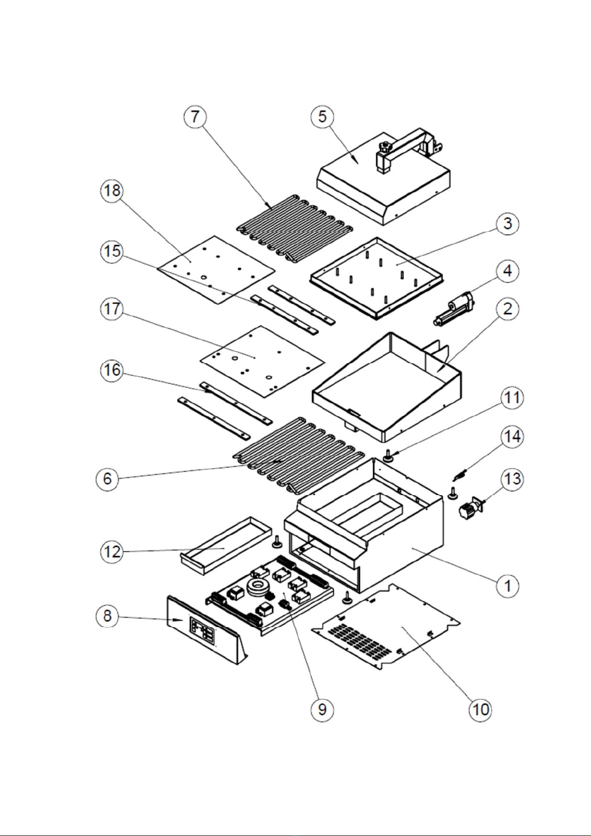
7.3.1. Specifications on spare parts
GL 9001

14
Pos. Part no. Pcs. Description
1 83-10314 1 Bottom cabinet GL 9001
2 83-10315 1 Pan GL 9001, lower
3 83-10279 1 Pan upper large
4 83-10022 1 Actuator MLA-2
5 83-10237 1 Top cabinet large incl. arm
6 83-09322 1 Heatelement lower 4,7 kW 400V
7 83-09320 1 Heatelement upper 4,1 kW 400V
8 83-10323 1 Frontpanel incl. PCB and key.pad
9 83-20103 1 Electrical components – see wiring diagram
10 83-09975 1 Bottom plate GL 9001/3
11 82-06510 4 Leg M8 adjustable
12 83-09980 1 Fat drawer
13 84-00067 1 Switch 4-polet CA25 32 A
13a 84-00292 1 Handle for switch
14 84-00290 1 Fuse holder
14a 84-00289 1 Fuse 2A
15 83-09313 2 Tension piece large upper
16 83-09312 2 Tension piece lower
17 83-09119 1 Cover plate upper large
18 83-10194 1 Cover plate lower

15
GL 9002
Pos. Part no. Pcs. Description
1 83-10292 1 Bottom cabinet GL 9002
2 83-10293 1 Pan GL 9002 lower
3 83-10237 1 Top cabinet large incl. arm
4 83-10279 1 Pan upper large
5 83-10325 1 Top cabinet small incl. arm
6 83-10324 1 Frontpanel double incl. PCB and key-pad

16
Pos. Part no. Pcs. Description
7 83-10022 2 Actuator MLA-2
8 83-20104 1 Electrical components – see wiring diagram
9 83-09980 1 Fat drawer
10 83-10288 1 Bottom plaet 600 mm
11 83-09981 1 Pan small
12 83-09320 1 Heat element upper 4,1 kW 400V
13 83-09322 1 Heat element lower 4,7 kW 400V
14 83-09323 1 Heat element lower 2,6 kW 400V
15 83-09323 1 Heatelement upper 2,3 kW 400V
16 82-06510 4 Leg M8 adjustable
17 84-00067 1 Switch 4-polet CA 25 32A (400V)
17a 84-00292 1 Handle for switch type CA
18 84-00290 1 Fuse holder
18a 84-00289 1 Fuse 2A
19 83-09119 1 Cover plate lower large
20 83-10194 1 Cover plate upper large
21 83-09120 1 Cover plate lower small
22 83-10195 1 Cover plate upper small
23 83-09313 2 Tension piece upper large
24 83-09312 2 Tension piece lower large
25 83-09329 2 Tension piece upper small
26 83-09135 2 Tnsion piece lower small

17
GL 9003

18
Pos. Part no. Pcs. Description
1 83-09984 1 Bottom cabinet GL 9003
2 83-10325 2 Top cabinet small incl. arm
3 83-10324 1 Frontpanel double incl. PCB and key-pad
4 83-10022 2 Actuator MLA-2
5 83-20105 1 Electrical components – see wiring diagram
6 83-09980 1 Fat drawer
7 83-09296 2 Pan GL 9003 lower
8 83-09320 2 Pan upper small
9 83-09321 2 Heat element upper 2,3 kW 400V
10 83-09323 2 Heat element lower 2,6 kW 400V
11 82-06510 4 Leg M8 adjustable
12 84-00067 1 Switch 4-polet CA25 32 A
12a 84-00292 1 Handle for switch
13 84-00290 1 Fuse holder
13a 84-00289 1 Fuse 2A
14 83-10195 2 Cover plate upper small
15 83-09120 2 Cover plate lower small
16 83-09312 2 Tension piece lower
17 83-09329 4 Tension piece upper small
18 83-09975 1 Bottom plate GL 9001/3

19
GL 9010

20
Pos. Part no. Pcs. Description
1 83-10332 1 Bottom cabinet GL 9010
2 83-10330 1 Pan GL 9010
3 83-10335 1 Top pan GL 9010
4 83-10337 1 Top cabinet GL 9010
5 83-10346 1 Arm GL 9010
6 83-10352 1 Adjusting bracket for actuator GL 9010
7 83-10353 2 Fat drawer GL 9010
8 83-10326 1 Bottom plate GL 9010
9 83-20103 1 Electrical components – see wiring diagram
10 83-10323 1 Frontpanel incl. PCB and key-pad
11 83-10333 6 Heat element 1,85 kW 400V
12 83-10325 1 Actuator LA 23
13 83-10096 1 Adjustingbolt for pan
14 83-10336 4 Tension piece GL 9010
15 83-10355 1 Cover plate lower GL 9010
16 83-10354 1 Cover plate upper GL 9010
17 84-00068 1 Seitch 4-pole CA20 25A
18 83-00086 1 Cooling fan80x80x25 24V DC
19 84-00290 1 Fuse holder
19a 84-00289 1 Fuse 2A
20 83-10099 1 Mounting plate for 25A switch
21 83-10317 1 Cover back
22 82-06510 4 Leg M8 adjustable
This manual suits for next models
4
Table of contents
Other FKI Grill manuals


Popular Grill manuals by other brands


MaxxGarden
MaxxGarden 20732 Manual instruction

CONTINENTAL EDISON
CONTINENTAL EDISON CERP6PERS2 Instruction booklet

Nexgrill
Nexgrill 720-0441-LP Assembly & operating instructions

Targa
Targa TGR 2000 A1 User manual and service information

George Foreman
George Foreman GR100VC Use and care book

Brinkmann
Brinkmann TRAILMASTER 30" owner's manual


