17
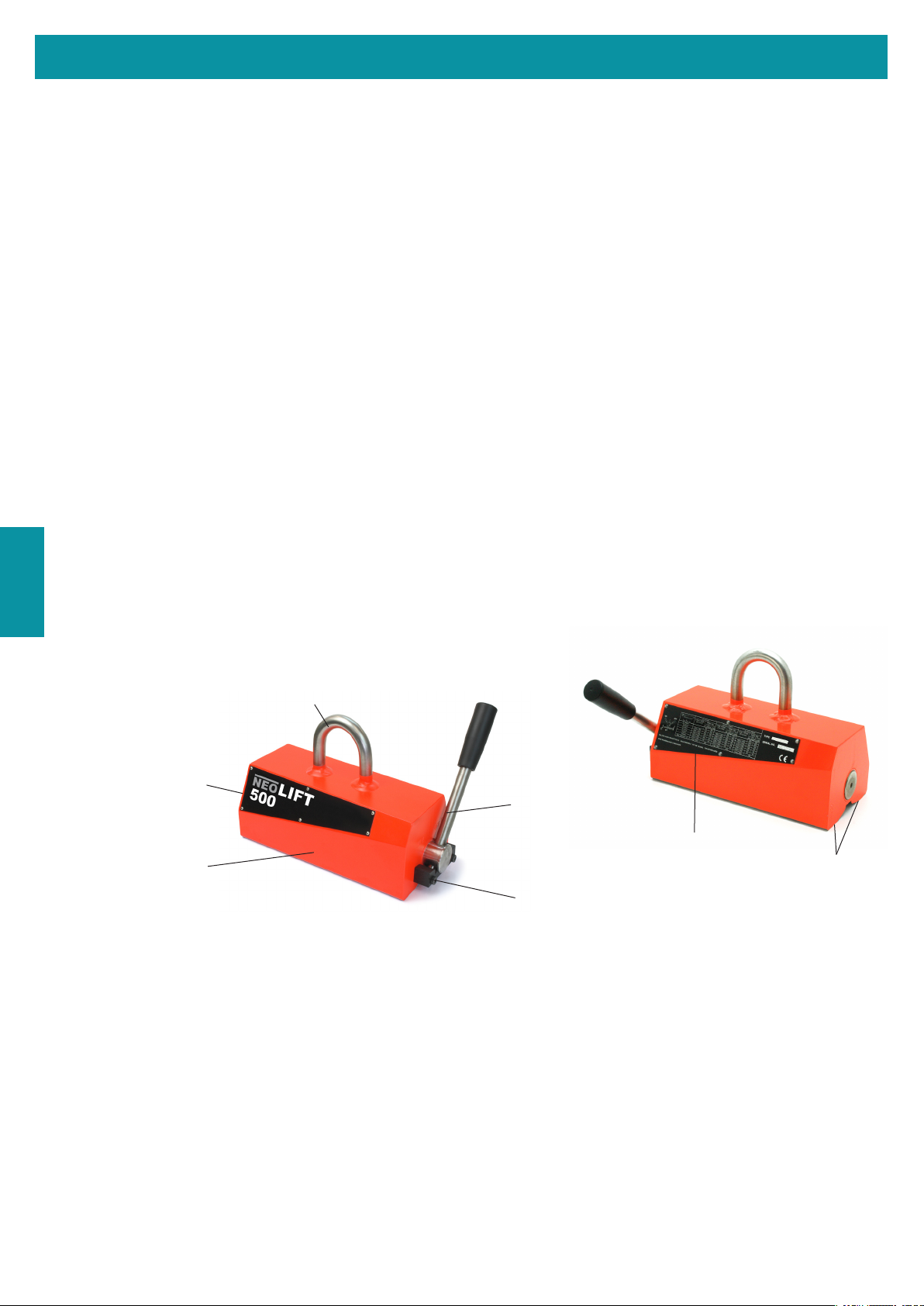
Instrucciones de manejo y mantenimiento para los modelos NEO-LIFT
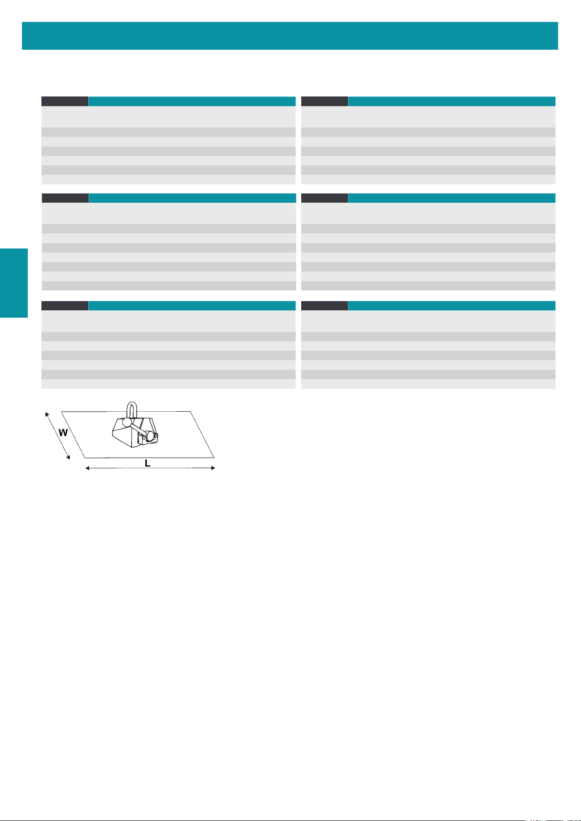
POTENCIA ELEVADORA RECOMENDADA PARA PLACAS, BARRAS Y TUBOS (St37):
NEO-LIFT 250
Abertura de aire < 0,1mm
Abertura de aire 0,1 - 0,3 mm Abertura de aire 0,3 - 0,5 mm
Espesor material
(mm) Max.
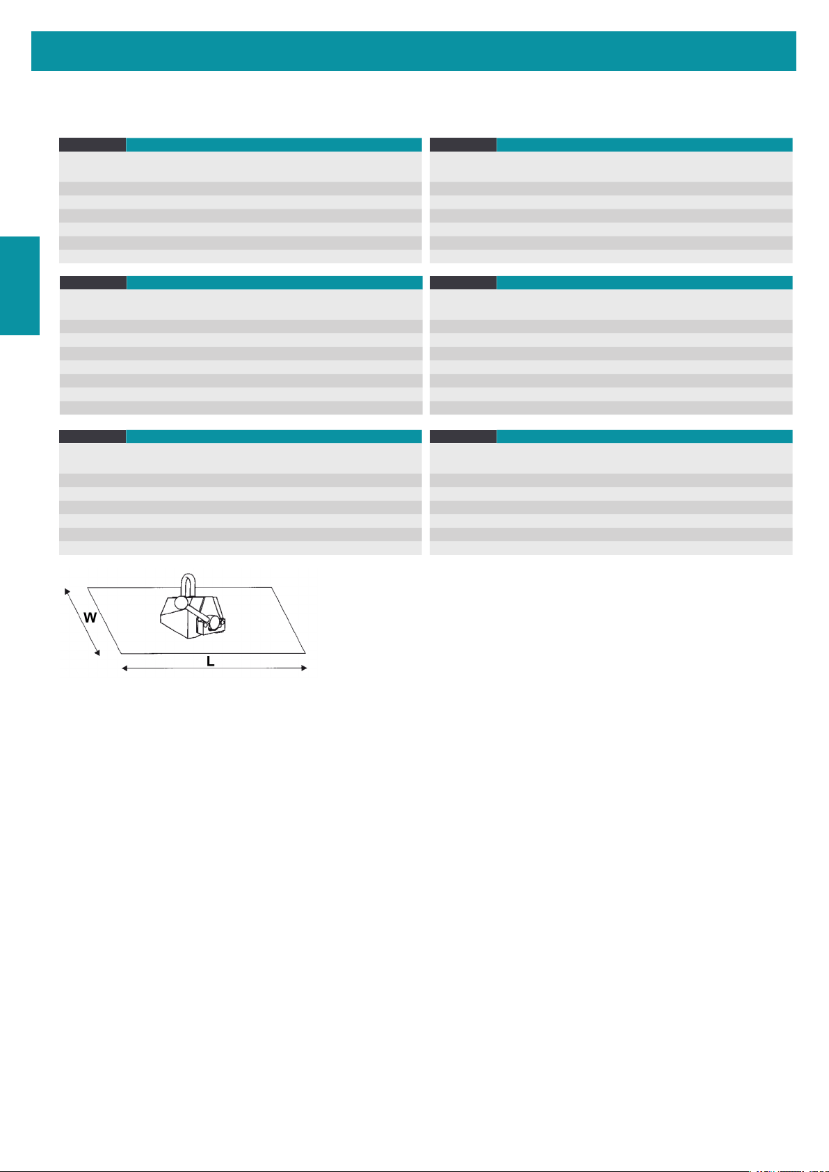
L
(mm)
Max.
W
(mm)
Peso
max.
(kg)
Max.
L
(mm)
Max.
W
(mm)
Peso
max.
(kg)
Max.
L
(mm)
Max.
W
(mm)
Peso
max.
(kg)
>= 25 2250 1000 250 2000 1000 170 1500 1000 105
>= 15 2250 1000 205 2000 1000 150 1500 1000 90
>= 10 2250 1000 170 2000 1000 130 1500 1000 85
>= 6 1750 1000 100 1500 1000 80 1350 1000 60
>= 4 1600 1000 50 1400 1000 45 1000 1000 36
Ø50 - Ø200mm 3500 - 125 3000 - 100 2500 - 70
NEO-LIFT 500
Abertura de aire < 0,1mm
Luftspalt 0,1 - 0,3 mm
Abertura de aire 0,3 - 0,5 mm
Espesor material
(mm) Max.
L
(mm)
Max.
W
(mm)
Peso
max.
(kg)
Max.
L
(mm)
Max.
W
(mm)
Peso
max.
(kg)
Max.
L
(mm)
Max.
W
(mm)
Peso
max.
(kg)
>= 30 2500 1500 500 2350 1250 380 2150 1000 255
>= 20 2500 1500 425 2350 1250 320 2150 1000 220
>= 15 2500 1500 400 2350 1250 300 2150 1000 205
>= 10 2500 1500 270 2350 1250 220 2150 1000 165
>= 8 2300 1500 195 2250 1250 160 2000 1000 125
>= 6 2000 1500 125 2000 1250 100 2000 1000 80
Ø65 - Ø270mm 4000 - 250 3500 - 200 3000 - 150
NEO-LIFT 1000 Abertura de aire < 0,1mm
Abertura de aire 0,1 - 0,3 mm Abertura de aire 0,3 - 0,5 mm
Espesor material
(mm) Max.
L
(mm)
Max.
W
(mm)
Peso
max.
(kg)
Max.
L
(mm)
Max.
W
(mm)
Peso
max.
(kg)
Max.
L
(mm)
Max.
W
(mm)
Peso
max.
(kg)
>= 40 3000 1500 1000 3000 1500 845 2500 1250 650
>= 30 3000 1500 860 3000 1500 730 2500 1250 565
>= 25 3000 1500 830 3000 1500 705 2500 1250 550
>= 20 3000 1500 745 3000 1500 640 2500 1250 510
>= 15 3000 1500 500 3000 1500 445 2500 1250 380
>= 10 2750 1500 285 2500 1500 240 2000 1250 200
Ø100 - Ø300mm 4500 - 500 4000 - 400 3500 - 300
NEO-LIFT 1500 Abertura de aire < 0,1mm
Luftspalt 0,1 - 0,3 mm
Abertura de aire 0,3 - 0,5 mm
Espesor material
(mm) Max.
L
(mm)
Max.
W
(mm)
Peso
max.
(kg)
Max.
L
(mm)
Max.
W
(mm)
Peso
max.
(kg)
Max.
L
(mm)
Max.
W
(mm)
Peso
max.
(kg)
>= 60 3500 2000 1500 3500 2000 1240 2500 2000 975
>= 50 3500 2000 1300 3500 2000 1100 2500 2000 880
>= 30 3500 1500 1000 3500 1500 860 2500 1500 750
>= 20 3000 1500 825 3000 1500 750 2500 1500 675
>= 15 3000 1500 480 3000 1500 450 2500 1500 410
Ø150 - Ø350mm 4500 - 750 4000 - 675 3500 - 600
NEO-LIFT 2000 Abertura de aire < 0,1mm
Abertura de aire 0,1 - 0,3 mm Abertura de aire 0,3 - 0,5 mm
Espesor material
(mm) Max.
L
(mm)
Max.
W
(mm)
Peso
max.
(kg)
Max.
L
(mm)
Max.
W
(mm)
Peso
max.
(kg)
Max.
L
(mm)
Max.
W
(mm)
Peso
max.
(kg)
>= 60 3500 2000 2000 3500 2000 1650 3000 1500 1300
>= 50 3500 2000 1600 3500 2000 1300 3000 1500 1100
>= 30 3500 2000 1350 3500 2000 1150 2500 1500 1000
>= 20 3000 2000 1100 3000 1500 1000 2500 1500 900
>= 15 3000 1500 650 3000 1500 600 2000 1500 550
Ø150 - Ø350mm 5000 - 1000 4500 - 900 4000 - 800
• Nunca eleve planchas o tubos de espesor menor al que se indica en Ia tabla.
• En caso de tubos con un esperor de pared minimo, Ia capacidad de elevación puede delimitarse mediante Ia
Iongitud máxima.
MANTENIMIENTO E INSPECCION DEL IMAN ELEVADOR
• Antes de cada uso: Inspeccione visualmente el imán en su totalidad. Limpie a fondo las zapatas polares y
elimine eventuales rebabas o irregularidades con una lima. No use el imán cuando se ha comprobado Ia
presencia de defectos, Controle el funcionamiento del jación de Ia palanca.
• Cada semana: Inspeccione Ia posible existencia de deformaciones, suras u otros defectos en el imán,
incluyendo en Ia anilla de transporte y jaciones de las tuercas. Si Ia argolla de izada esta deformada o des
gastado por más del 10%, deberá ser reemplazada. Controle Ia presencia y Iegibilidad de Ia placa de
datos y de instrucciones. Inspeccione las zapatas polares. Si están danadas más de un 10% (hoyuelos,
rebabas,etc;), su abastecedor o agente autorizado debe de pulirlas Después de esta operación se controlará
Ia potencia elevadora.
• Cada ano; Haga controlar Ia potencia elevadora de su imán elevador por su abastecador o agente autoriza
do, una vez por ano, como minimo.
MANlOBRA EN HORIZONTAL Y VERTICAL?
Utilice el brazo de elevatión "HV", muy útil para cambiar de Ia posición horizontal a la vertical y viceversa.
Solicite más información.
ESP
NEO-LIFT 125
Abertura de aire < 0,1mm
Abertura de aire 0,1 - 0,3 mm Abertura de aire 0,3 - 0,5 mm
Espesor material
(mm) Max.
L
(mm)
Max.
W
(mm)
Peso
max.
(kg)
Max.
L
(mm)
Max.
W
(mm)
Peso
max.
(kg)
Max.
L
(mm)
Max.
W
(mm)
Peso
max.
(kg)
>= 20 1500 1000 125 1250 800 75 1000 600 60
>= 15 1500 1000 115 1250 800 70 1000 600 55
>= 10 1250 1000 110 1000 800 65 750 600 50
>= 4 800 800 45 600 600 40 500 600 30
>= 2 500 500 15 400 500 13 400 500 12
Ø50 - Ø100mm 2500 - 60 2500 - 40 2500 - 25